

Page 1

Operating Instruction
for
Humidity/Temperature- Measuring
Instrument
Model: AFH-G
Page 2

AFH-G
Seite 2 AFH-G 07/02
1. Note
Please read and take note of these operating instructions before unpacking and
setting the unit for operation, and follow the instructions precisely as described
herein.
The devices are only to be used, maintained and serviced by persons familiar
with these operating instructions and with the prevailing regulation applying to
procedural safety and the prevention of accidents.
2. Contents
1. Note.................................................................................... 2
2. Contents ............................................................................. 2
3. Specific Application ............................................................ 3
4. Operating Principles ........................................................... 3
5. Instrument Inspection ......................................................... 5
6. Mechanical connection ....................................................... 5
7. Electrical connection........................................................... 7
8. Technical Data.................................................................... 8
9. Order Codes....................................................................... 9
10. Maintence and Instruction for use ...................................... 9
11. Calibration ........................................................................ 10
12. Dimensions....................................................................... 11
13. Declaration of Conformance............................................. 12
Manufactured and sold by:
Kobold Messring GmbH
Nordring 22-24
D-65719 Hofheim
Tel.: +49(0)6192-2990
Fax: +49(0)6192-23398
E-Mail: info.de@kobold.com
Internet: www.kobold.com
Page 3

AFH-G
AFH-G 07/02 Seite 3
3. Specific Application
The AFH-G is to be installed only in the specified applications. Every usage
which exceeds the specifications is considered to be non-specified. Any damages resulting thereform are not the responsibility of the manufacturer. The user
assumes all risk for such usage. The application specifications include the installation, start-up and service requirements specified by the manufacturer.
4. Operating Principles
The type AFH-G measuring instrument serves to measure relative humidity indoors and in air ducts. Auxiliary temperature measurement is available as an option.
The moisture sensing element in the sensor comprises several strips of plastic
fabric each with 90 fibres of 3 µm diameter. These plastic fibres undergo a special process to acquire hygroscopic properties, this means that they absorb and
release moisture. The molecular structure of the fibres changes when they absorb water, giving rise to a measurable change in length. The length of the plastic
fibres is thus a measure of the relative humidity.
The swelling effect, acting primarily in the longitudinal direction, is sensed by an
electronic pick-off system and transferred to an integrated signal preprocessing
system. The output signal of the passive sensors is 100-138.5 ., and
4- 20 mA for the active sensors.
The special treatment of the measuring element ensures that its hygroscopic
properties remain stable, that is sensitivity is maintained until destroyed by external influence. Regeneration found in conventional instruments is not required
here, but is also not damaging.
The measuring element is protected by a perforated tube and is open to the
housing.
Measuring instruments with an integrated temperature sensor provide temperature measurement. The temperatures are also converted to the standardized
signals 0-20 mA, 0-10 V , and 4-20 mA.
4.1. Design of the sensor
The expanding action (predominantly lengthways) of the fibres is picked up by
means of an electronic sensing system and converted by integrated signal preprocessing into standardised signals 0..20mA or 4..20mA or 0...10V.
Page 4
AFH-G
Seite 4 AFH-G 07/02
The fan-shaped measuring element, which faces outward from the housing, is
protected by a perforated sensor tube. The sensors are designed for pressureless systems. The unit should be installed in a location where condensation cannot enter into the housing. A preferred position would be ”sensor vertically down”
or ”sensor horizontal”. In these positions, a cover plate with a 0.8 mm diameter
hole will prevent water from entering.
The AFH-G range of sensors have built-in temperature sensors (mainly Pt100)
for simultaneous measurement of temperature. Temperature readings are converted likewise into standardised signals 0..20mA or 4..20mA or 0..10V.
4.2. Ageing
In order to maintain their long-term stability, it is important that the measuring
elements undergo a special ageing process, details of which cannot be given
here.
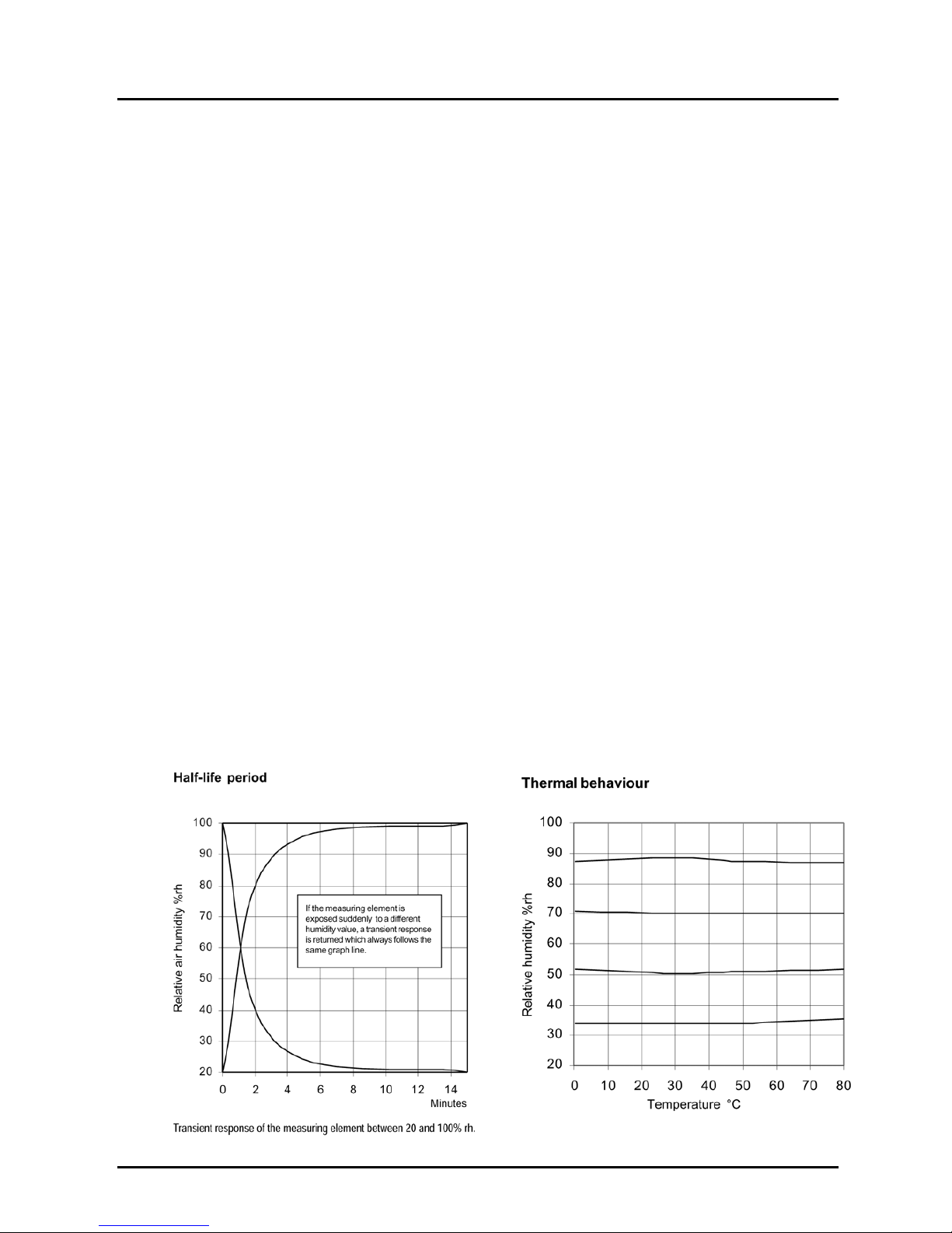
4.3. Reaction of the sensor
Due to the law of diffusion, there is a time delay before the fibres are saturated
during water absorption. This is a decisive factor when determining the reaction
time. Thus, for one individual fibre with a diameter of 3 µm, a short saturation
time (several seconds) can be measured. Empirical investigations show that
bundled or woven fibres, as are used here in the Kobold sensor, give rise to a
longer period prior to saturation. This is because the individual fibres impede
each other during water absorption and/or water loss, and the ensuing humidity
does not register until later. Measurements have shown that, at a wind speed of
2m / sec. the half-life period is 1.2 mins. This represents an effective period of
approx. 30 - 40 mins.
Page 5

AFH-G
AFH-G 07/02 Seite 5
80º C is given as the maximum temperature value. Higher temperatures can only
be tolerated for a short period of time. The eventual result is a change in the
molecular structure which causes a constant error. The maximum temperature of
80º C only applies, however, if no harmful substances (acids, solvents etc.) are
present in the medium.
4.4. Humidity and tolerance diagram
5. Instrument Inspection
These devices are checked before dispatch and sent away in perfect condition.
Should the damage to a device be visible, we recommend a thorough inspection
of the delivery packing. In case of damage, please inform your parcel service/
forwarding agent immediately, since they are responsible for damages during
transit.
Scope of delivery:
· Measuring Unit Model “AFH-G”
· Operating Instructions
6. Mechanical connection
Unavoidable sources of interference should be kept at a good distance
from the control systems.
Data and signalling lines should not be used in parallel with control,
networking and power lines.
Page 6

AFH-G
Seite 6 AFH-G 07/02
For data and signalling lines, shielded cable should be used, and the shielding
must be applied to the earth terminal. Ensure that earth circuits and fault currents
do not arise as a result of a second earth connection.
For equipment with a network connection, it is recommended that a separate
network circuit be used.
During the switch process, electrical power consumers such as switch contactors,
magnetic valves etc. produce induction voltages that can cause interference. In
the trade there is an abundance of protective and suppressor component parts
that are most effective when applied directly to the source of the trouble. A suitable suppressor has the added advantage that components such as relays, microswitches etc. have a longer service life.
Further difficulties during installation can arise if signalling lines are joined together with common lines. It is essential to check whether this is permissible. Interference is particularly likely when installing using equipment of different
makes. Here, too, the trade offers isolating amplifiers that overcome the problem.
Installation:
The installation position should be chosen so as to prevent condensed water
from entering the housing. The preferred installation position is "sensor vertically
pointing downwards" or "sensor horizontal".
A grommet in the probe prevents penetration of water in the installation positions
described above.
Wall mounting set
Page 7

AFH-G
AFH-G 07/02 Seite 7
7. Electrical connection
7.1. Passive sensors
7.2. Active sensors
Page 8

AFH-G
Seite 8 AFH-G 07/02
8. Technical Data
8.1. Humidity
Measuring range: 0-100% RH
Measuring accuracy: > 40% RH: ±2.5% RH
< 40% RH: ±3.5% RH
Recommended
operating range: 30-100% RH
8.2. Temperature
Measuring range: passive sensors: +5 to +80°C
active sensors: -30 to +60°C
Measuring accuracy: ±0.5°C
Measured medium: air, pressureless, non-aggressive
Allowed ambient
temperature: at housing: -20 to +60°C
at sensor: -40 to +80°C
Average temperature
coefficient: -0.1% RH/K
(at 20°C and 50% RH)
Allowed air speed: 8 m/s
with gauze protection
(optional) 15 m/s
Half-life at V=2 m/s: 1.2 min
Sensor length: 220 mm
Sensor material: stainless steel
Mounting: holes in housing base
for duct mounting
Bracket for surface
mounting (optional)
Installation position: sensor vertical pointing down,
or horizontal
Connection terminals: for conductor cross-sections
0.5 mm
Cable connection: Cable gland PG 13.5
Electromagnetic
compatibility:
Noise immunity: EN 50 082-2
emitted interference: EN 50 081-2
Housing: ABS
Protection: IP 64
Weight: approximately 0.4 kg
Page 9

AFH-G
AFH-G 07/02 Seite 9
9. Order Codes
10. Maintence and Instruction for use
The measuring element is maintenance free when the surrounding air is clean.
Agents that are corrosive and contain solvents, depending upon the type and
concentration of the agent, can result in faulty measurements and cause the
measuring element to break down. Direct sunlight should be avoided. Substances deposited on the sensor are damaging as they eventually form a waterrepellent film (this applies to all humidity sensors with hygroscopic measuring
elements). Such substances are resin aerosols, lacquer aerosols, smoke deposits etc. The water-resistant property of the Kobold sensors allows for cleaning
using water. Solvents cannot be used for this purpose. A light-duty detergent is
recommended. Any detergent residue should, however, always be thoroughly
washed out. A special process ensures that Kobold sensors have good long-term
stability. Regeneration is not necessary, but is also not harmful.
The temperature coefficient as well as the self-heating may vary according to the
location and the application (especially with sensors where electronic and measuring system are integrated in one housing).
The guarantee is no longer valid if the interior of the measuring element
has been accessed.
Page 10

AFH-G
Seite 10 AFH-G 07/02
11. Calibration
Kobold sensors are adjusted correctly at a room temperature of 23ºC and 50%rh
at a mean air pressure corresponding to 430m NN. If, however, a further adjustment is necessary, the following procedure should be adhered to :
· Ensure that the ambient humidity as well as the ambient temperature are
constant.
· If possible, use a psychrometer for testing, (do not use testing equipment with
capacitive sensors).
· Leave the equipment to be tested for a minimum of 1 hour under constant
test conditions.
· All Kobold sensors are equipped with an adjustment facility. In most cases
this involves an adjuster screw fixed with screw securing lacquer. When the
lacquer is removed the screw can be adjusted. After calibration, the adjuster
screw should again be secured.
Important: The air’s capacity to absorb water is influenced among other factors
by the temperature. This is a physical law (identified in the hx diagram of Mollier).
The higher the air temperature, the larger the amount of steam that can be absorbed up to saturation point (100%rh). If a sensor is calibrated under varying air
temperature conditions, the result is an irregular, unhomogenous measuring medium which automatically gives calibration errors. The table below shows the influence of the air temperature on air humidity. If, for example, calibration occurs
at an air temperature of 20ºC and 50%rh and a varying temperature range of only
+/-1 ºK, this results in a variation in humidity of the measuring medium (air) of +/-
3.2%rh.
Page 11

AFH-G
AFH-G 07/02 Seite 11
12. Dimensions
Page 12

AFH-G
Seite 12 AFH-G 07/02
13. Declaration of Conformance
We, KOBOLD-Messring GmbH, Hofheim-Ts, Germany, declare under our sole
responsibility that the product:
Humidity/Temperature- Measuring Instrument Model: AFH-G
to which this declaration relates is in conformity with the standards noted below:
DIN EN 60730-2-1 1993
VDE 0631 2 1989
IEC 730-2-1
Also the following EWG guidlines are fulfilled:
73/23/EWG
89/336/EWG
Unterschrift: Datum: 22.06.01
 Loading...