

Page 1
Model No. / N
CH0330SQB
CH0336SQB
CH0342SQB
CH0348SQB
KOBE Brand Range Hood
os
de modèles / Modelo No.
CH-03 SERIES – 18” HEIGHT
INSTALLATION INSTRUCTIONS
AND OPERATION MANUAL
MANUEL D'INSTALLATION
ET MODE D'EMPLOI
INSTRUCCIONES DE INSTALACIÓN
Y MANUAL DE OPERACIÓN
Page 2

[ENGLISH]................................................................................................................................. 1
[FRENCH]................................................................................................................................ 28
[SPANISH]............................................................................................................................... 55
Page 3

[ENGLISH]
- READ AND SAVE THESE INSTRUCTIONS -
CONTENTS
IMPORTANT SAFETY INSTRUCTIONS .................................................................................... 2
COMPONENTS OF PACKAGE.................................................................................................. 4
INSTALLATION.......................................................................................................................... 5
OPERATION INSTRUCTIONS................................................................................................. 12
MAINTENANCE....................................................................................................................... 13
SPECIFICATIONS ................................................................................................................... 15
MEASUREMENTS & DIAGRAMS............................................................................................ 16
PARTS LIST............................................................................................................................. 18
CIRCUIT DIAGRAM.................................................................................................................21
TROUBLE SHOOTING ............................................................................................................ 23
DISCLAIMER ........................................................................................................................... 24
WARRANTY ............................................................................................................................ 25
PRODUCT REGISTRATION.................................................................................................... 27
- READ ALL INSTRUCTIONS CAREFULLY BEFORE STARTING -
ALL WIRING MUST BE DONE BY A PROFESSIONAL AND IN
ACCORDANCE WITH NATIONAL AND LOCAL ELECTRICAL CODES.
1
Page 4
IMPORTANT SAFETY INSTRUCTIONS
- PLEASE READ THIS SECTION CAREFULLY BEFORE INSTALLATION -
WARNING
1) Installation and electrical wiring must be done by qualified professionals and in accordance with all
applicable codes and standards, including fire-rated construction.
2) When cutting or drilling into wall or ceiling, be careful not to damage electrical wiring or other hidden
utilities.
3) Ducted fans must be vented to the outside.
a) Before servicing or cleaning unit, open the light panel and SWITCH POWER OFF AT SERVICE
PANEL.
b) Clean all grease laden surfaces frequently. To reduce the risk of fire and to disperse air
properly, make sure to vent air outside. DO NOT vent exhaust air into wall spaces, attics, crawl
spaces or garages.
NOT E - This warranty is invalid without an authorized agent’s receipt or if unit is
- KOBE RANGE HOODS will not be held responsible for any damages to
:
TO REDUCE THE RISK OF FIRE, ELECTRIC SHOCK OR PERSONAL
INJURY, OBSERVE THE FOLLOWING:
damaged due to misuse, poor installation, improper use, mistreatment,
negligence or any other circumstances beyond the control of KOBE
RANGE HOODS authorized agents. Any repair carried out without the
supervision of KOBE RANGE HOODS authorized agents will
automatically void the warranty.
personal property or real estate or any bodily injuries whether caused
directly or indirectly by the range hood.
WARNING
1. Keep all fan, baffle/spacer/filter/oil tunnel/oil container and grease-laden surfaces clean. Grease
should not be allowed to accumulate on fan, baffle/spacer/filter/oil tunnel/oil container.
2. Always turn hood ON when cooking.
3. Use high settings on cooking range ONLY when necessary.
4. Do not leave cooking range unattended when cooking.
5. Always use cookware and utensils appropriate for the type and amount of food prepared.
6. Use this unit only in the manner intended by the manufacturer.
7. Before servicing, switch power off at service panel and lock service panel (if possible) to prevent
power from switching on accidentally.
8. Clean ventilating fan frequently.
: TO REDUCE THE RISK OF PERSONAL INJURY IN THE EVENT OF A RANGE
TOP GREASE FIRE:
2
Page 5
What to Do In The Event Of a Range Top Grease Fire
• SMOTHER FLAMES with a tight fitting lid, cookie sheet, or metal tray, and then turn off the burner.
KEEP FLAMMABLE OR COMBUSTIBLE MATERIAL AWAY FROM FLAMES. If the flames do not
go out immediately, EVACUATE THE AREA AND CALL THE FIRE DEPARTMENT or 911.
• NEVER PICK UP A BURNING PAN – You May Get Burned.
• DO NOT USE WATER, including wet dishcloths or towels – a violent steam blast will result.
• Use an extinguisher ONLY if:
a) You have a Class A, B, C extinguisher and know how to operate it.
b) The fire is small and contained in the area where it started.
c) The fire department has been called.
d) You can fight the fire with your back to an exit.
What to Do If You Smell Gas
-
Extinguish any open flame.
-
Do not try to turn on the lights or any type of appliance.
-
Open all doors and windows to disperse the gas. If you still smell gas, call the Gas Company and
Fire Department right away.
CAUTION
1) For general ventilation use only. Do not use to exhaust hazardous or explosive materials and
vapors.
2) To reduce the risk of fire, use only metal ductwork. Sufficient air is needed for proper combustion
and exhausting of gases through the flue (chimney) to prevent back drafting.
3) Follow the heating equipment manufacturer’s guideline and safety standards such as those
published by the National Fire Protection Association (NFPA), and the American Society for
Heating, Refrigeration and Air Conditioning Engineers (ASHRAE), and code authorities.
4) Activating any switch on may cause ignition or an explosion.
5) Due to the size and weight of this hood, two people installation is recommended.
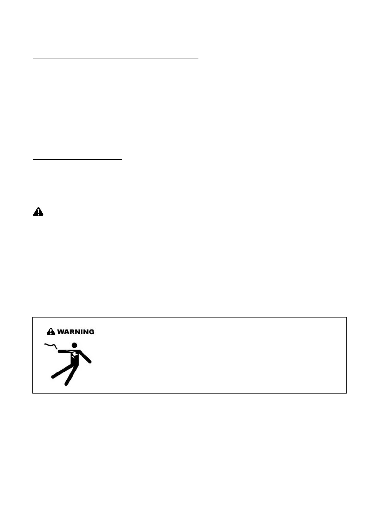
ELECTRICAL SHOCK HAZARD – Can result in serious injury or death.
Disconnect appliance from electric power before servicing. If equipped,
the fluorescent light bulb contains small amounts of mercury, which
must be recycled or disposed of according to Local, State, and Federal
Codes.
3
Page 6
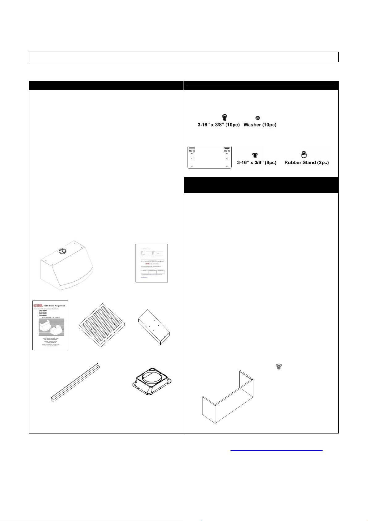
COMPONENTS OF PACKAGE
(Must keep all material for returns or refunds)
RANGE HOOD BOX
KOBE Range Hood – 1
Warranty Registration Card –1
Instructions Manual – 1
Baffle Filter
- 2 (30”, 36”, 42”)
- 3 (48”)
Stainless Steel Spacer
- 1 (30”)
- 3 (36”)
- 3 (42”)
- 2 (48”)
Oil Tunnel – 1
Ducting Transition – 1
Screw Package for Transition – 1
Hood-Mounting Bracket-2
Screw Package for Hood-Mounting Bracket–1
ORIGINAL KIT
(Sold Separately)
Option Of:
Model No. CH0030DC-12 for 30'' hood
KOBE Duct Cover – 1
Screw Package for Duct Cover - 1
Hood-Mounting Bracket-2
Model No. CH0036DC-12 for 36'' hood
KOBE Duct Cover – 1
Screw Package for Duct Cover - 1
Hood-Mounting Bracket-2
Model No. CH0042DC-12 for 42'' hood
KOBE Duct Cover – 1
Screw Package for Duct Cover - 1
Hood-Mounting Bracket-2
Model No. CH0048DC-12 for 48'' hood
KOBE Duct Cover – 1
Screw Package for Duct Cover - 1
Hood-Mounting Bracket-2
3/16" X 3/8" (8 pc)
-
FOR MORE INFORMATION, PLEASE VISIT OUR WEBSITE www.KOBERangeHoods.com OR
CONTACT KOBE RANGE HOODS AT (626)-775-8880.
4
Page 7
INSTALLATION
PLEASE READ ENTIRE INSTRUCTIONS BEFORE PROCEEDING
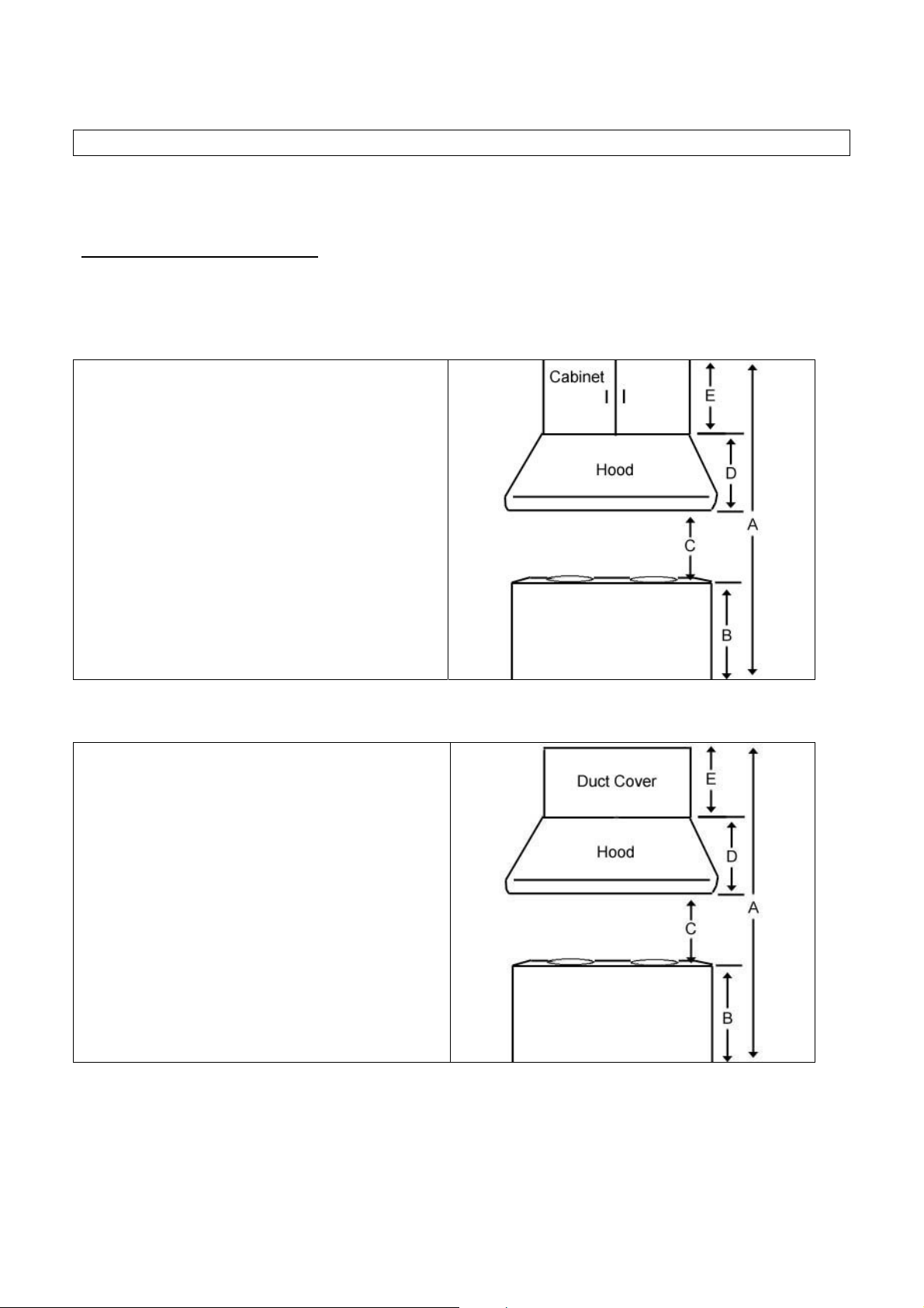
Calculation before Installation
Calculate the length of the installation, before installing the hood. (All calculation is measure in inches.)
- FOR UNDER THE CABINET -
TABLE 1
A = Height of Floor to Ceiling
B = Height of Floor to Counter Top
(Standard: 36”)
C = Preferred Height of Counter Top to Hood
Bottom (Recommended 27” to 30”)
D = Height of Hood
E = Height of the Cabinet
- FOR WALL MOUNT (WITH OPTIONAL DUCT COVER) -
TABLE 2
A = Height of Floor to Ceiling
B = Height of Floor to Counter Top
(Standard: 36”)
C = Preferred Height of Counter Top to Hood
Bottom (Recommended 27” to 30”)
[(A – B] – (D + E)]
D = Height of Hood
E = Height of Duct Cover
5
Page 8

SAFETY WARNING
HOOD MAY HAVE VERY SHARP EDGES; PLEASE WEAR PROTECTIVE GLOVES IF IT IS
NECESSARY TO REMOVE ANY PARTS FOR INSTALLING, CLEANING OR SERVICING.
NOTE: BE CAREFUL WHEN USING ELECTRICAL SCREWDRIVER, DAMAGE TO THE HOOD
MAY OCCUR.
Installation Contents
UNDER THE CABINET INSTALLATION ............................................................................................... 7
WALL MOUNT INSTALLATION............................................................................................................. 9
6
Page 9
UNDER THE CABINET INSTALLATION
Preparation before Installation
NOTE: TO AVOID DAMAGE TO YOUR HOOD,
PREVENT DEBRIS FROM ENTERING
THE VENT OPENING.
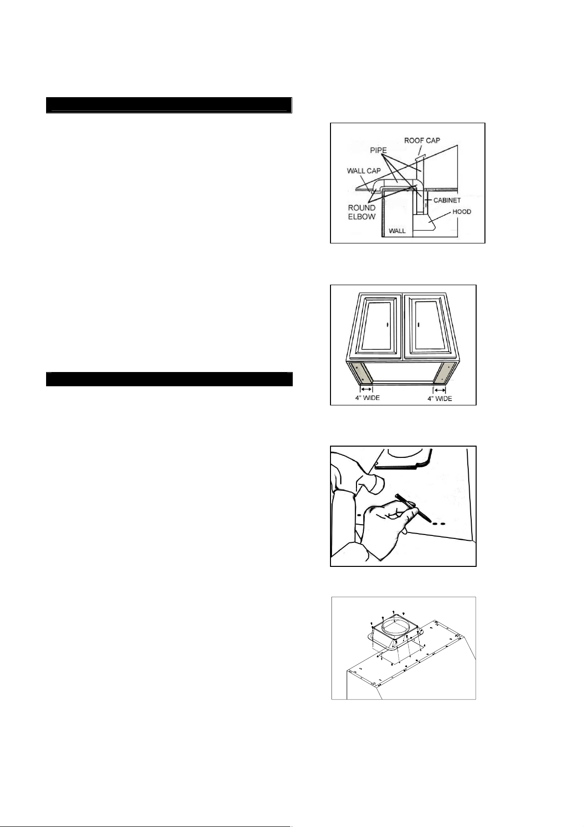
Decide the location of the venting pipe from the
hood to the outside. Refer to Figure 1.
A straight, short venting run will allow the hood
to perform more efficiently.
Try to avoid as many transitions, elbows, and
long run as possible. This may reduce the
performance of the hood.
Temporarily wire the hood to test for proper
operation before installing.
Important: Peel protective film off the hood
(if any).
For installing under the cabinet with recessed
bottom, attach 4-inch wide wood filler strips (not
included) on each side. Refer to Figure 2.
Measure and create access opening for
electrical wires under the cabinet.
Figure 1
Figure 2
Hood Installation
CAUTION: If required to move the cooking
range to install the hood, turn off the power on
an electric range at the main electrical box.
SHUT OFF THE GAS BEFORE MOVING A GAS
RANGE.
1. Puncture the knockout holes on the hood as
shown in Figure 3.
2. Attach ducting transition to hood exhaust with
ten (3/16” x 3/8”) screws (included). Shown in
Figure 4.
3. Using references on Table 1 and
measurements on page 16-17 to center the
hood in place beneath the cabinet and flush
with the front of the cabinet.
4. Draw electrical wires through cabinet access
opening.
5. From the bottom of the hood, place screw (not
provided) into the exact center of each
knockout hole. Make sure all screws are in
place before tightening screws. CAUTION:
MAKE SURE THE HOOD IS SECURE
BEFORE RELEASING.
6. For safety purpose, pre-drilled mounting holes
are provided through the back of the hood. For
a more secure installation, use as many
mounting holes as needed to secure from the
inside of hood (screws not included).
7
Figure 3
Figure 4
Page 10
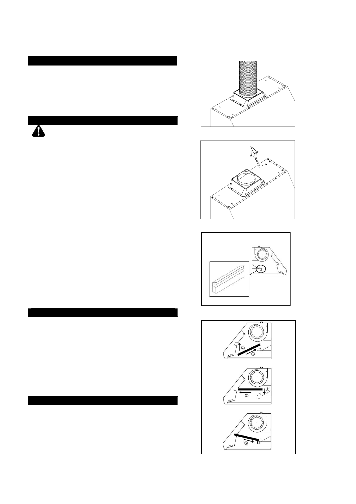
Ductwork Installation
7. Use 8” round steel pipe (follow building codes
in your area) to connect the ducting transition
on the hood to the ductwork above. Use duct
tape to make all joints secure and air tight.
Refer to Figure 5.
Wiring to Power Supply
Figure 5
SAFETY WARNING
RISK OF ELECTRICAL SHOCK. THIS RANGE
HOOD MUST BE PROPERLY GROUNDED.
MAKE SURE THIS IS DONE BY SPECIALIZED
ELECTRICIAN IN ACCORDANCE WITH ALL
APPLICABLE NATIONAL AND LOCAL
ELECTRICAL CODES. BEFORE CONNECTING
WIRES, SWITCH POWER OFF AT SERVICE
PANEL AND LOCK SERVICE PANEL TO
PREVENT POWER FROM BEING SWITCHED
ON ACCIDENTALLY.
8. Connect the electrical wires.
-
Connect three wires (black, white and
green) to house wires and cap with wire
connectors. Connect according to color:
black to black, white to white, and green to
green as shown on Figure 6.
-
If necessary to hide the electrical wire
connections, push wires back into the
wiring box. Access the wire connections
underneath the hood. Make sure wires do
not slip between motor or any moving parts
to prevent any damage.
Figure 6
Figure 7
Install Accessories
9. Attach Oil Tunnel. Refer to Figure 7.
10. Refer to Figure 8. Slide the baffle filter into
the hood. Push the baffle filter upward.
Slide forward. Pull downward. Fit into
place.
11. Repeat for all baffle filters and spacers. Refer
to page 17.
12. Install heating lamps (not included), 120 Volts
175 Watts max. each.
Final Assembly
13. Turn power ON in control panel. Check all
lights and fan operation.
14. Make sure to leave this manual for the
homeowner.
Figure 8
8
Page 11
WALL MOUNT INSTALLATION
***This installation only applied with the purchase
of an optional duct cover:
Preparation before Installation
NOTE: TO AVOID DAMAGE TO YOUR HOOD,
PREVENT DEBRIS FROM ENTERING
THE VENT OPENING.
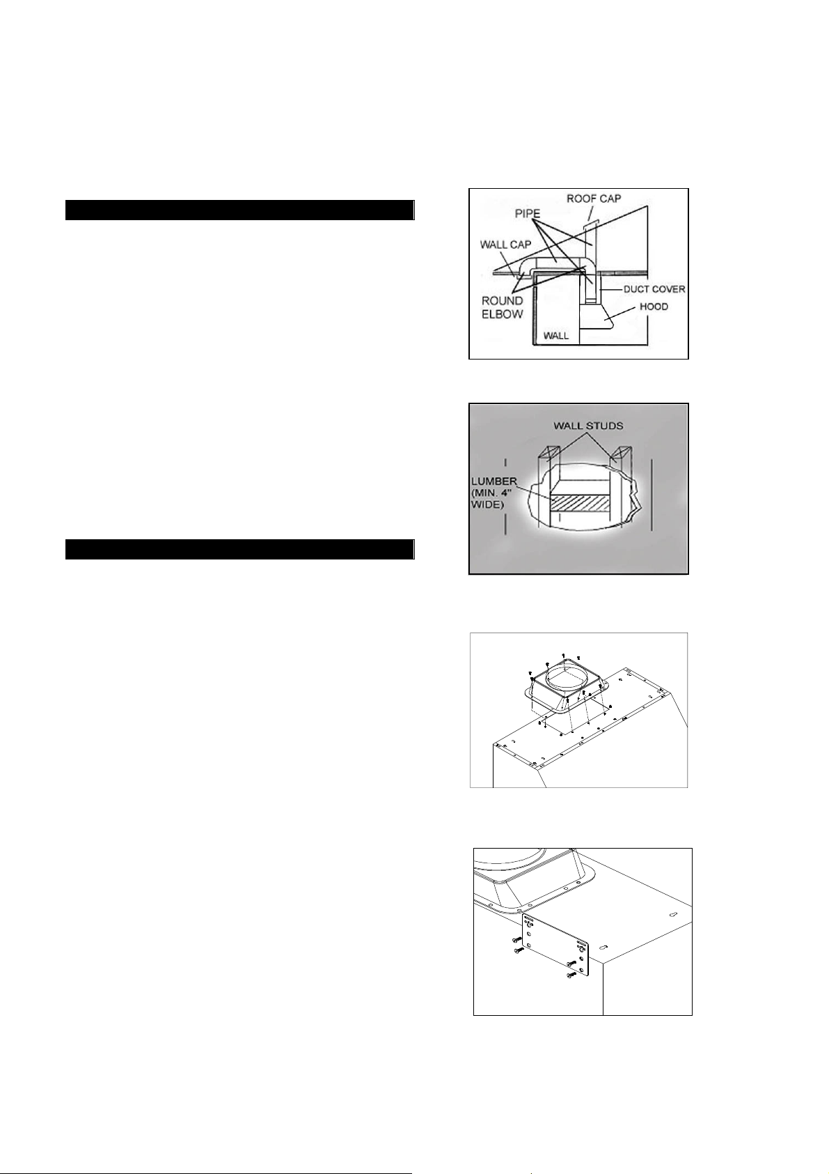
Decide the location of the venting pipe from the
hood to the outside. Refer to Figure 9.
A straight, short venting run will allow the hood
to perform more efficiently.
Try to avoid as many transitions, elbows, and
long run as possible. This may reduce the
performance of the hood.
Use duct tape to seal the joints between pipe
sections.
If necessary, prepare back wall frame with
cross framing lumber for secure installation.
Using references on Table 2 and
measurements on page 16-17, decide the level
of the lumber. Refer to Figure 10.
Hood Preparation before Installation
• Temporarily wire the hood to test for proper
operation before installing.
• Important: Peel protective film off the hood
and the duct cover (if any).
• Attach ducting transition to hood exhaust with
ten (3/16” x 3/8”) screws (included). Refer to
Figure 11.
• If necessary, attach two rubber stands
(included) with adhesive tape (included) to the
back corners of the hood.
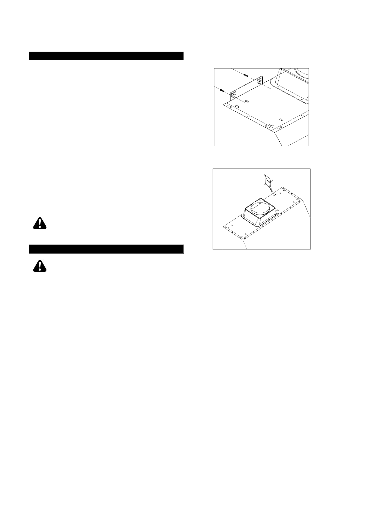
• Use eight (3/16” x 3/8”) screws (included) to
attach the two hood-mounting brackets
(included) to the back of the hood. Refer to
Figure 12.
Figure 9
Figure 10
Figure 11
Figure 12
9
Page 12
Hood Installation
Figure 13
CAUTION: If required to move the cooking
range to install the hood, turn off the power on
an electric range at the main electrical box.
SHUT OFF THE GAS BEFORE MOVING A GAS
RANGE.
1. Using references in Table 2 on page 4 and
Measurements and Diagrams on pages 16-17,
mark the leveling point of the hood. Position
two mounting screws (not included) on the wall,
leaving 1/8” away from the wall. Refer to Figure
13.
2. Align hood-mounting bracket to the two screws
on the wall and hook hood into place. Tighten
screws to secure hood to the wall.
3. For safety purpose, pre-drilled mounting holes
are provided through the back of the hood. For
a more secure installation, use as many
mounting holes as needed to secure from the
inside of hood (screws not included).
CAUTION: MAKE SURE HOOD IS
SECURE BEFORE RELEASING.
Wiring to Power Supply
WALL
Figure 14
SAFETY WARNING
RISK OF ELECTRICAL SHOCK. THIS RANGE
HOOD MUST BE PROPERLY GROUNDED.
MAKE SURE THIS IS DONE BY SPECIALIZED
ELECTRICIAN IN ACCORDANCE WITH ALL
APPLICABLE NATIONAL AND LOCAL
ELECTRICAL CODES. BEFORE CONNECTING
WIRES, SWITCH POWER OFF AT SERVICE
PANEL AND LOCK SERVICE PANEL TO
PREVENT
POWER FROM BEING SWITCHED ON
ACCIDENTALLY.
4. Connect the electrical wires.
-
Connect three wires (black, white and
green) to house wires and cap with wire
connectors. Connect according to color:
black to black, white to white, and green to
green as shown on Figure 14.
-
If necessary to hide the electrical wire
connections, push wires back into the
wiring box. Access the wire connections
underneath the hood. Make sure wires do
not slip between motor or any moving parts
to prevent any damage.
10
Page 13
Duct Cover Installation
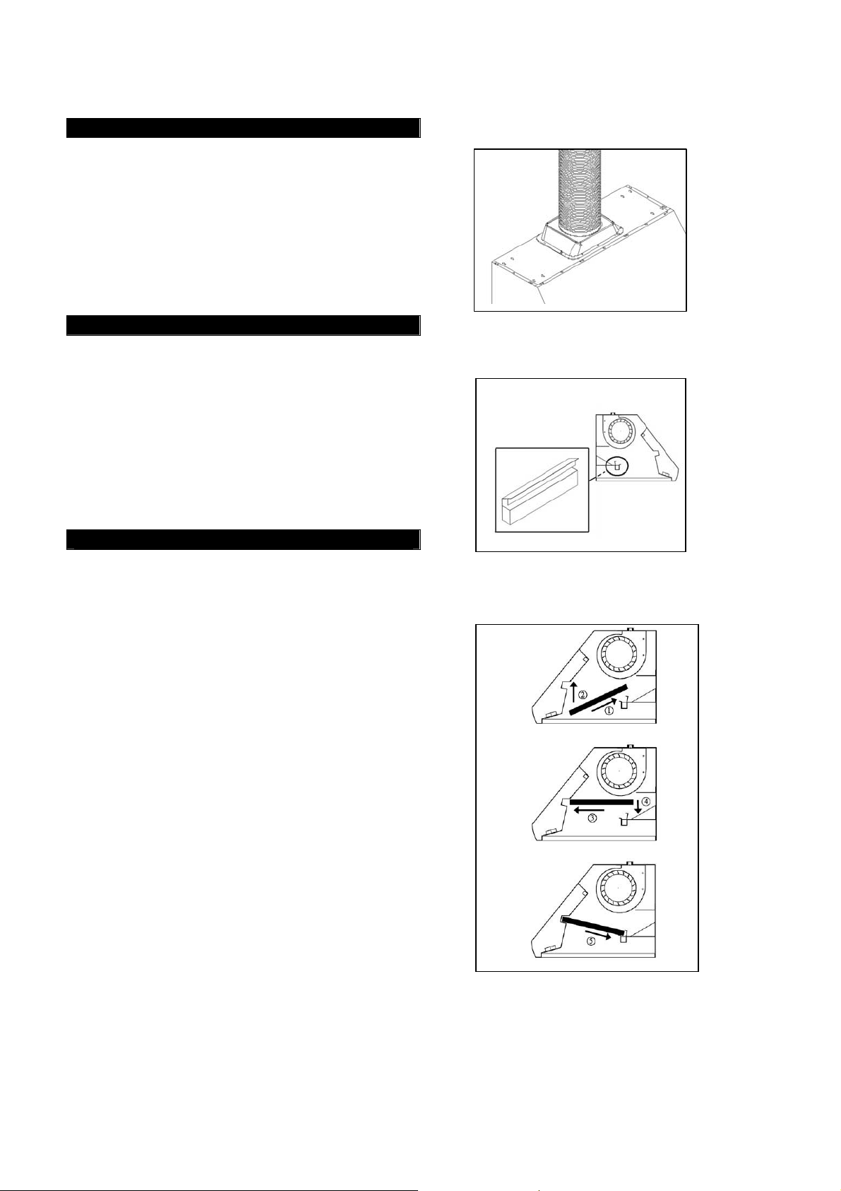
5. Use 8” round steel pipe (follow building codes
in your area) to connect the ducting transition
on the hood to the ductwork above. Use duct
tape to make all joints secure and air tight.
Refer Figure 15. Slide the duct cover onto the
hood.
6. Use 3/16” x 3/8” screws (included) to attach
duct cover to hood.
Figure 15
Install Accessories
7. Attach oil tunnel. Refer to Figure 16.
8. Refer to Figure 17. Slide the baffle filter into
the hood. Push the baffle filter upward.
Slide forward. Pull downward. Fit into
place.
9. For bottom casing, repeat above steps. Refer
to page 17.
10. Install heating lamps (not included), 120 Volts
175 Watts max. each.
Final Assembly
11. Turn power ON in control panel. Check all
lights and fan operation.
12. Make sure to leave this manual for the
homeowner.
Figure 16
Figure 17
11
Page 14
OPERATION INSTRUCTIONS
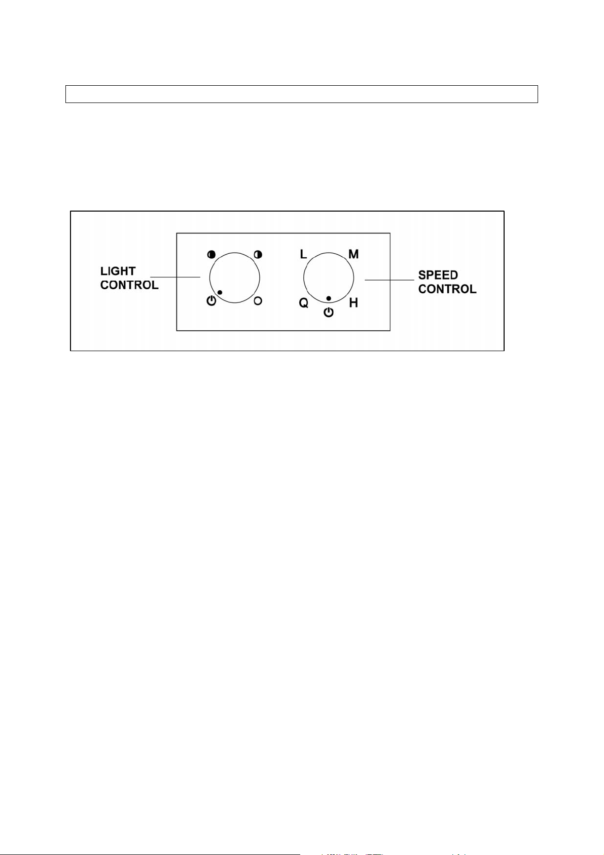
This KOBE hood is equipped with two rotary controls with powerful centrifugal squirrel cage,
baffle filters, and bright 12-volt 20-watt halogen lights.
The two rotary controls are Light Control & Speed Control. Refer to Figure 18.
Figure 18
Note: For best results, turn hood to QuietMode™ prior to preparation or cooking to
establish airflow in the kitchen. Adjust speed as needed.
•
Rotate the Speed Control clockwise to cycle from QuietMode™, Low, Medium,
High, and Off; and rotate counterclockwise to cycle from High, Medium, Low,
QuietMode™, and off
•
Rotate the Light Control clockwise to cycle the light intensity through low,
medium, high, and off.
•
Press the back Red button to turn on heating lamp.
(Note: Heating lamps are sold separately. Heating lamps required 120-volt,
175-watt.)
12
Page 15

MAINTENANCE
For the optimal level of operation, clean the range hood surface and baffles regularly.
To Clean Hood Surface
CAUTION: NEVER USE ABRASIVE CLEANERS, PADS, OR CLOTHS.
*** Regular care will help preserve its fine appearance.
1. Use only mild soap or detergent solutions. Dry surfaces using soft cloth.
2. If hood looks splotchy (stainless steel hood), use a stainless steel cleaner to clean the
surface of the hood. Avoid getting cleaning solution onto or into the control panel.
Follow directions of the stainless steel cleaner. Caution: Do not leave on too long as
this may cause damage to hood finish. Use soft towel to wipe off the cleaning
solution, gently rub off any stubborn spots. Use dry soft towel to dry the hood.
3. DO NOT allow deposits to accumulate or remain on the hood.
4. DO NOT use ordinary steel wool or steel brushes. Small bits of steel may adhere to the
surface and cause rusting.
5. DO NOT allow salt solutions, disinfectants, bleaches, or cleaning compounds to remain
in contact with stainless steel for extended periods. Many of these compounds contain
chemicals, which may be harmful. Rinse with water after exposure and wipe dry with a
clean lint free cloth.
To Clean Baffle Filters & Oil Tunnel
CAUTION: DRAIN BAFFLE FILTERS AND OIL TUNNEL BEFORE OIL WILL OVERFLOW.
1. Remove the baffle filters and oil tunnel.
2. Using a sponge, wash with warm soapy water. Dry completely before returning into
place.
(Note: Baffle Filters are top rack dishwasher safe.)
13
Page 16
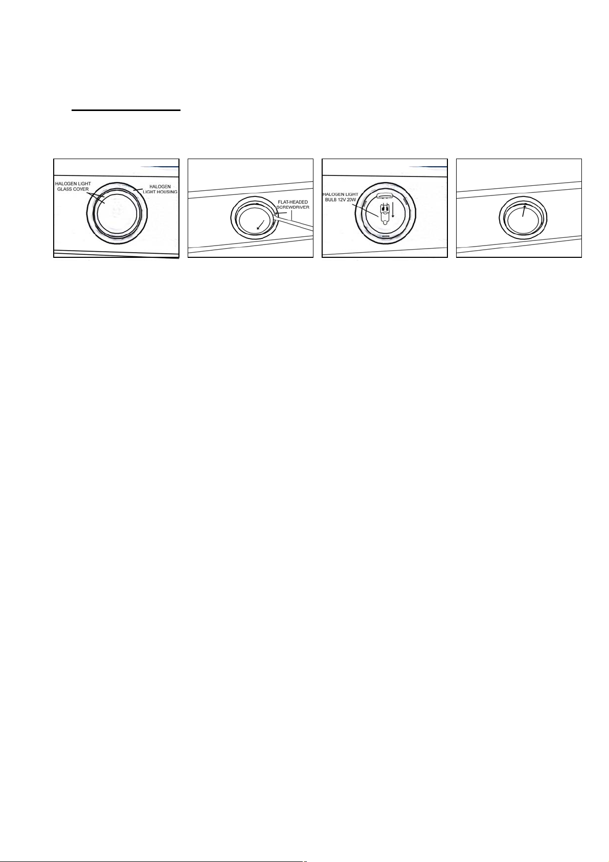
Replacing Light Bulb
CAUTION: HALOGEN LIGHT UNIT MAY BE HOT! WAIT UNTIL UNIT IS COOL.
1. Make sure all controls are off, and range hood is unplugged.
2. Place the flat-headed screwdriver into the groove of the halogen light glass covering and
the housing.
3. Pop out the halogen light glass covering.
4. Gently pull out the defective light bulb and discard. Light bulbs should be 12V 20W
maximum.
5. Using a cloth, hold the new light bulb and push securely into light socket.
6. Return halogen light glass cover to the housing.
7. Turn range hood ON to test for operation.
14
Page 17

SPECIFICATIONS
MODEL / SIZE
COLOR
CONSUMPTION / AMPERE
VOLTAGE
NUMBER OF MOTORS
DESIGN
FAN TYPE: CENTRIFUGAL
EXHAUST
CONTROLS
HALOGEN LIGHTS
HOOD DIMENSION
(W x D x H)
OPTIONAL ACCESSORIES
(W x D x H)
HOOD WEIGHT (lbs)
SPEED
Air Capacity (cfm)
Sone*
CH0330SQB / 30”
CH0336SQB / 36"
CH0342SQB / 42”
CH0348SQB / 48”
Commercial Grade Stainless Steel
CH0330SQB – 300W / 2.68A
CH0336SQB – 300W / 2.68A
CH0342SQB – 320W / 2.86A
CH0348SQB – 320W / 2.86A
120V 60Hz
1
18-Gauge Seamless / Satin Finish
Squirrel Cage
Top Transition Rectangular to 8” Round
Rotary Control
12V 20W x 2 – 30”, 36”
12V 20W x 3 – 42”, 48”
(CH0330SQB) 29-3/4” x 25” x 18”
(CH0336SQB) 35-3/4” x 25” x 18”
(CH0342SQB) 41-3/4” x 25” x 18”
(CH0348SQB) 47-3/4” x 25” x 18”
1) Original Kit - Duct Cover:
Model No. CH0030DC-12 30” x 12” x 12”
Model No. CH0036DC-12 36” x 12” x 12”
Model No. CH0042DC-12 42” x 12” x 12”
Model No. CH0048DC-12 48” x 12” x 12”
2) Model No. SSP30
30” Stainless Steel Back Panel 30” x 1/10” x 32”
3) Model No. SSP36
36” Stainless Steel Back Panel 36” x 1/10” x 32”
Net
(CH0330SQB)
(CH0336SQB)
(CH0342SQB)
(CH0348SQB)
QuietMode™
400 600 800 1000
1.4* 3.5 7.0 8.0
Gross
66.0 84.0
73.0 93.0
84.0 106.0
90.5 115.0
Low Medium High
*One sone is equivalent to the sound of a refrigerator at 40 decibels.
**Specifications subject to change without notice.
15
Page 18
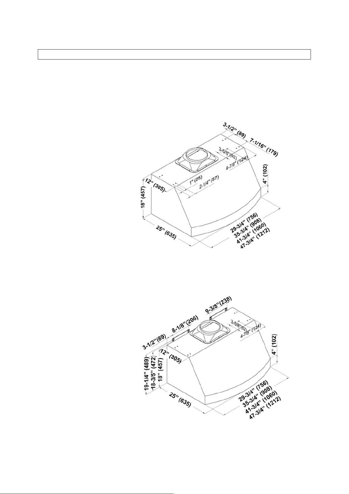
MEASUREMENTS & DIAGRAMS
All measurements in ( ) are millimeters.
All inch measurements are converted from millimeters. Inch measurements are
estimated.
- FOR UNDER THE CABINET -
MODEL NO.: CH0330SQB
CH0336SQB
CH0342SQB
CH0348SQB
- FOR WALL MOUNT -
MODEL NO.: CH0330SQB
CH0336SQB
CH0342SQB
CH0348SQB
16
Page 19
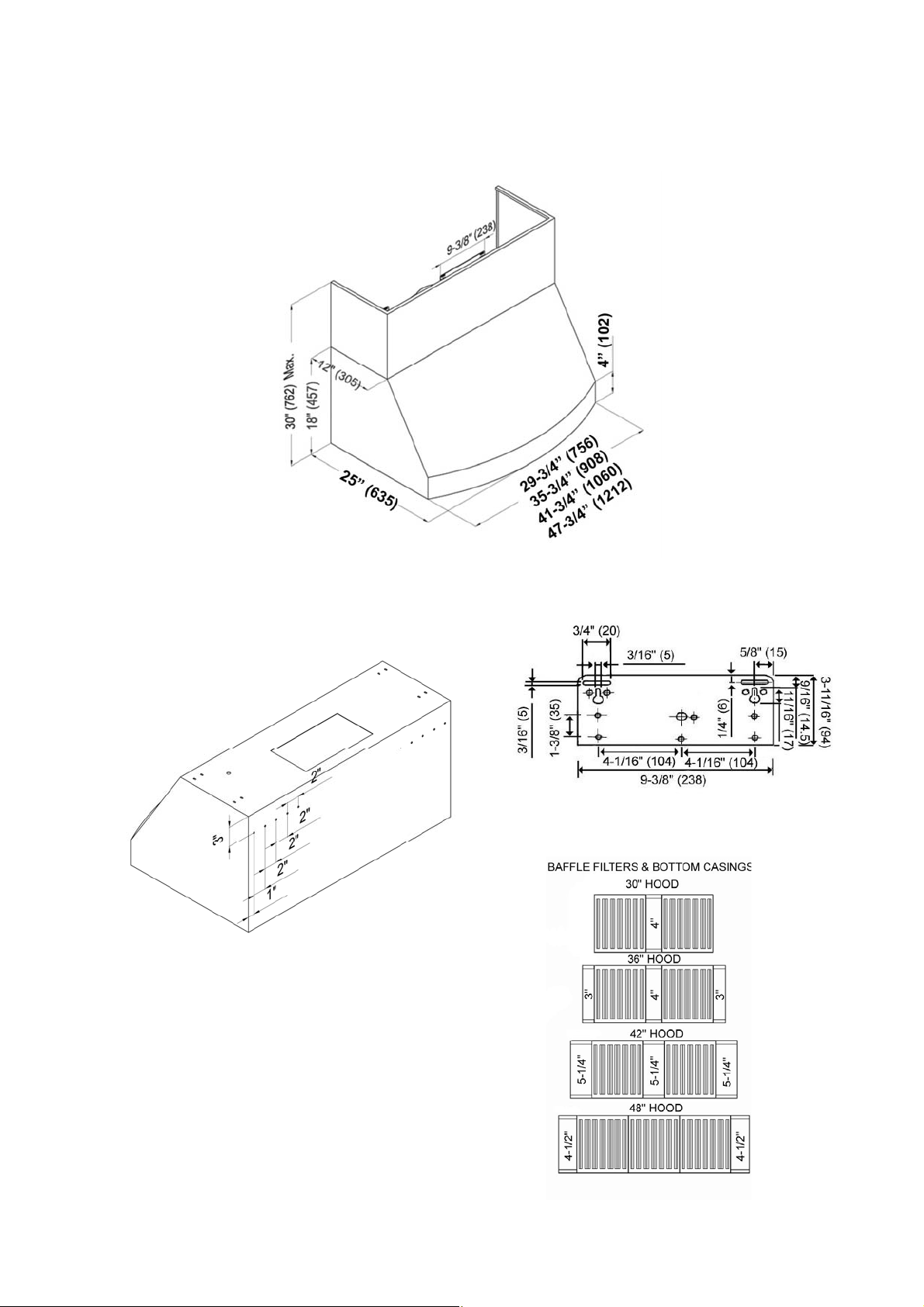
- FOR WALL MOUNT (WITH OPTIONAL DUCT COVER) -
***Rear Knocko ut Holes ***Hood-Mounting Bracket
17
Page 20
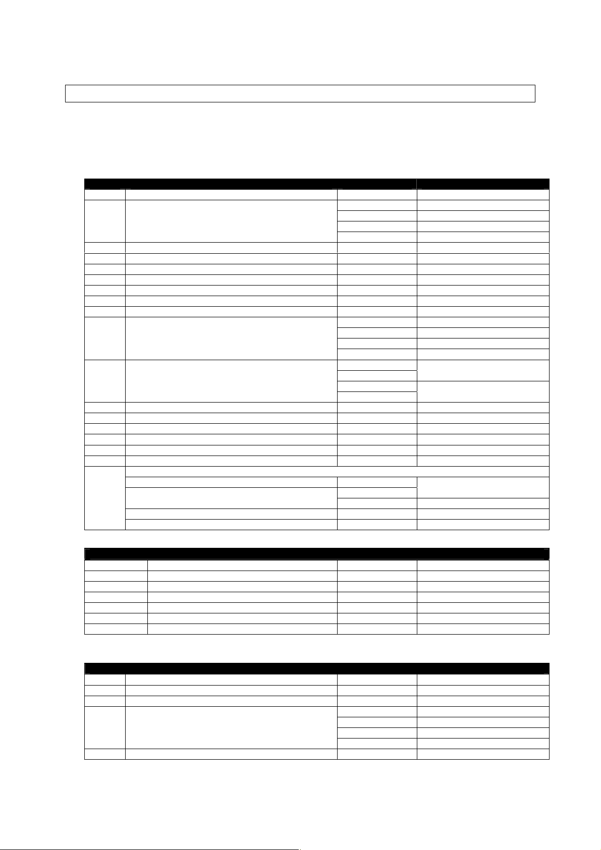
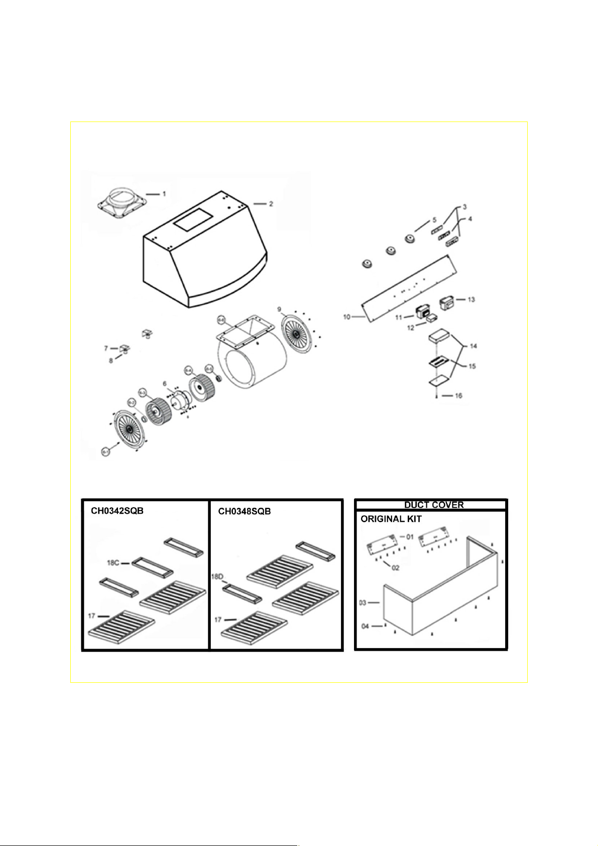
PARTS LIST
MODEL NO.: CH0330SQB
CH0336SQB
CH0342SQB
CH0348SQB
NO. DESCRIPTION MODEL /SIZE PART NO.
1 Ducting Transition FA-12001-0506-01 (B001-2)
2 Hood Casing
3 Control Unit C1-0501-0101
4 Control Board C1-0404-0401-A
5 Halogen Light Unit (12V 20W Max.) C1-0403-0101
6 Motor FA-12001-0302-01 (B001-4.5)
7 Lamp Socket Cover C1-0204-2130
8 Lamp Socket C1-0414-0120
9 Safety Screen FA-12001-0602-01 (B001-4.2)
10 Capacitor Panel
11 Transformer (Light)
12 Capacitor FA-12001-0401-01
13 Transformer (Motor) C1-0402-A-120-01
14 Processor Board Box C1-0501-0102
15 Processor Board C1-0404-0401-B
16 Screw (1/8” x 3/8”) C1-0708-0003
17 Baffle Filter B101-2130-15
18
Bottom Casing
A
4” Wide CH0030SQB
4” Wide
B
3” Wide
C
5-1/4” Wide CH0042SQB B101-2142-09
D
4-1/2” Wide CH0048SQB B101-2148-09
CH0330SQB 10-2130
CH0336SQB 10-2136
CH0342SQB 10-2142
CH0348SQB 10-2148
CH0330SQB C1-0201-2130
CH0336SQB C1-0201-2136
CH0342SQB C1-0201-2142
CH0348SQB C1-0201-2148
CH0330SQB
CH0336SQB
CH0342SQB
CH0348SQB
CH0036SQB
CH0036SQB B101-2136-09
C1-0402-0120-40
C1-0402-0120-60
B101-2130-09
BLOWER ASSEMBLY
NO. DESCRIPTION MODEL /SIZE PART NO.
6-1 Screws (3/16” x 3/8”) B001-4.1
6-2 Left Locknut B001-4.3
6-3 Left Squirrel Cage B001-4.4
6-4 Right Squirrel Cage B001-4.6
6-5 Right Locknut B001-4.7
6-6 Air Chamber B001-4.8
(Optional Duct Cover)
ORIGINAL KIT
NO. DESCRIPTION MODEL /SIZE PART NO.
01 Hood-Mounting Bracket C1-0221-0330
02 Screw (3/16” x 3/8”) C1-0707-0001
03 Duct Cover
04 Screw (3/16” x 3/8”) C1-0707-0001
CH0030DC-12 B102-6012-030
CH0036DC-12 B102-6012-036
CH0042DC-12 B102-6012-042
CH0048DC-12 B102-6012-048
18
Page 21
MODEL NO.: CH0330SQB
CH0336SQB
19
Page 22
MODEL NO.: CH0342SQB
CH0348SQB
20
Page 23
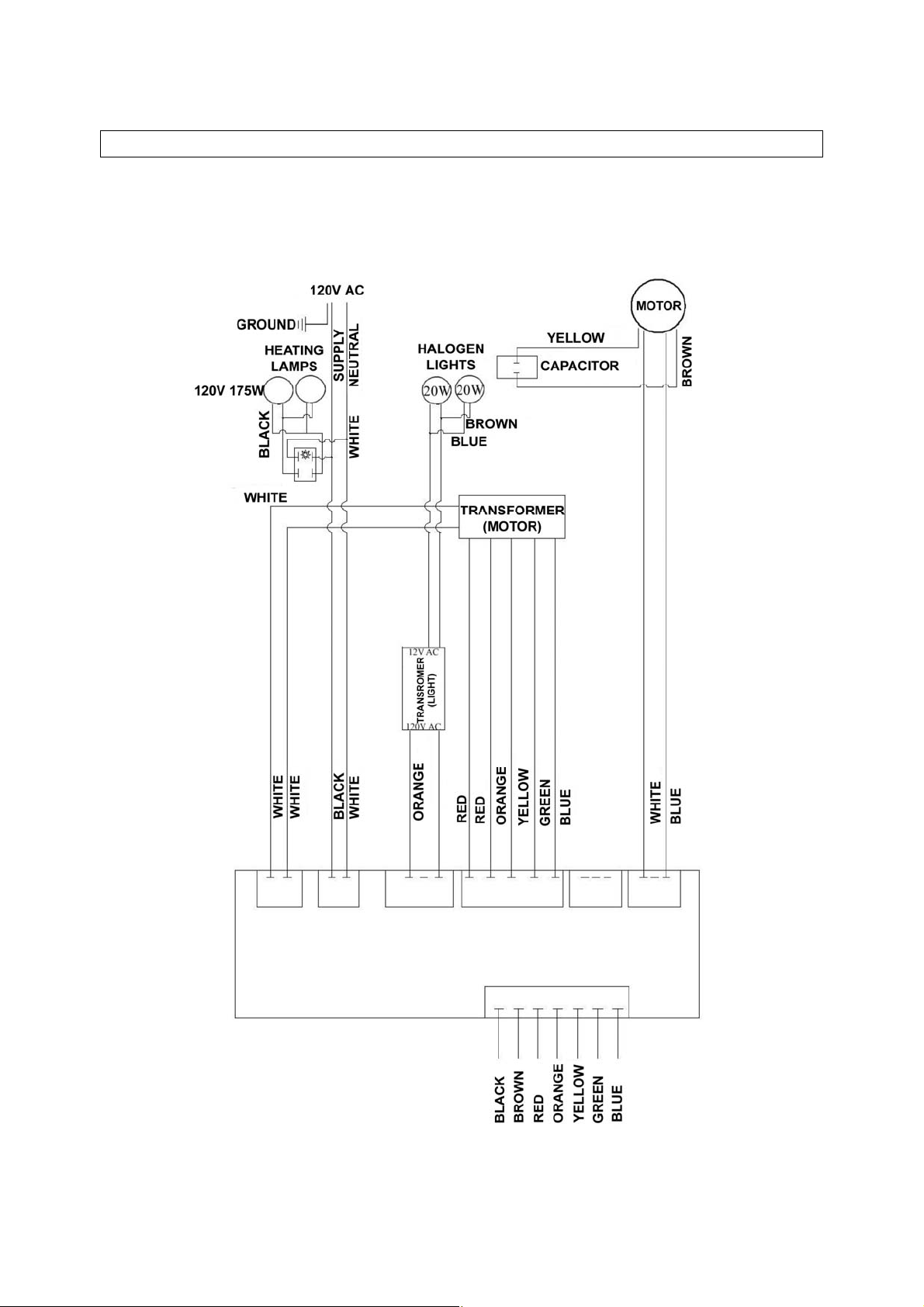
CIRCUIT DIAGRAM
MODEL NO.: CH0330SQB
CH0336SQB
21
Page 24
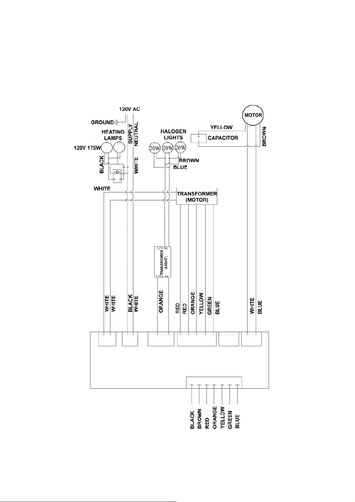
MODEL NO.: CH0342SQB
CH0348SQB
22
Page 25
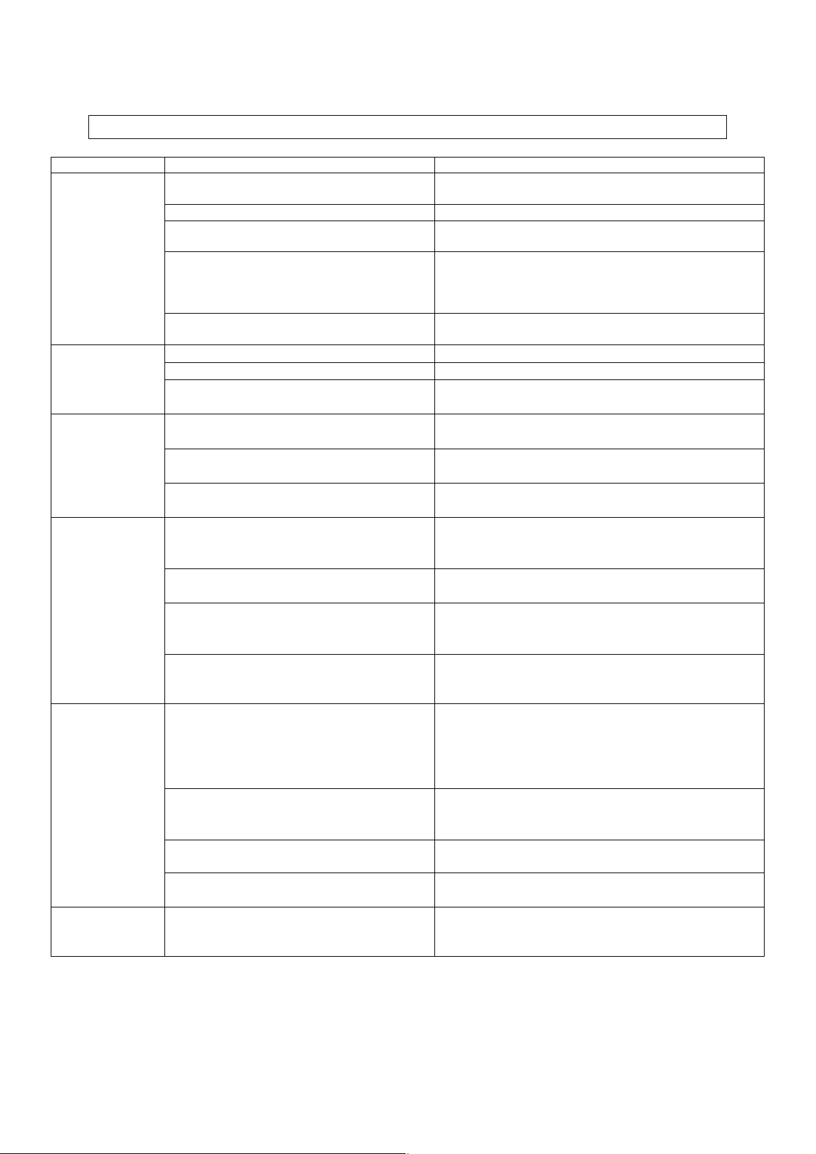
TROUBLE SHOOTING
Issue Possible Cause Solution
After Installation,
both motors and
lights are not
working.
The power is not on. Make sure the circuit breaker and the unit’s power is
ON. Use a voltage meter to check the power supply.
The wire connection is not secure. Check and tighten wire connection.
The control panel and processor board
wiring are disconnected.
The motor transformer is defective. Check the power input and power output on the
Check wire continuity from control panel to processor
board.
motor transformer.
If it’s needed, replace the motor transformer.
Lights are
working, but
motor(s) is not.
The range
hood is
vibrating.
The motor is
working, but
the lights are
not working.
The range
hood is not
venting out
correctly.
The control panel and processor board is
defective.
Replace the control panel or processor board.
The motor(s) is defective. Replace the motor.
The capacitor(s) is defective. Replace capacitor(s).
The control panel or processor board is
Replace the control panel or processing board.
defective.
The blower system is not secure. Tighten the turbine impeller/squirrel cage and air
chamber.
The turbine impeller/squirrel cage is
Replace the turbine impeller/squirrel cage.
not balanced.
Hood is not secured in place. Check the installation of hood, tighten the
mounting bracket.
Halogen Light bulb(s) is defective. Try placing the trouble light bulb(s) to a working
socket, if the bulb(s) still doesn’t work; replace
the halogen light bulb(s).
The light wiring(s) is loose. Check wire continuity from processor board to
light transformer to halogen light housing(s).
Light transformer is defective. Check power input and power output on the light
transformer. If it’s needed, replace the light
transformer.
The control panel or processor board is
Replace the control panel or processing board.
defective.
The range hood is installed outside of
the manufacture recommended
clearance.
Adjust the clearance between the range hoods
and cook top to 27” to 30”. For Island range
hood and professional series range hood, the
clearance between the range hoods and cook
top is 30” to 36”.
There is no make-up air inside the
house.
Open the window to enhance the performance
of the range hood by creating a sufficient make-
up air.
Obstacle blocking the pipe work. Remove all obstacles from the duct work.
Cold air is
coming into the
home.
The pipe size is smaller than the
suggested pipe size.
The pipe connection is not properly
sealed.
Change the ducting according to the
manufacture suggestion.
Check the pipe installation.
23
Page 26

DISCLAIMER
1. CAREFULLY INSPECT ALL ITEMS FOR DAMAGES BEFORE ACCEPTING DELIVERY.
NOTE ANY DAMAGES ON THE FREIGHT BILL OR EXPRESS RECEIPT. REQUEST
NAME AND SIGNATURE OF THE CARRIER’S AGENT AND KEEP COPY TO SUPPORT
YOUR CLAIM.
Upon acceptance of items, owner assumes responsibility for its safe arrival. Report
damages to the carrier and file a claim immediately. Failure to do so may result in the denial
of your claim. The carrier will furnish you with necessary forms for filing a claim.
DAMAGES CAUSED DURING TRANSIT ARE NOT COVERED UNDER OUR
WARRANTY.
2. PLEASE INSPECT CONTENTS OF PACKAGE(S) CAREFULLY UPON RECEIVING!
We must be notified in writing of any damages and/or missing parts within the allocated days
upon your receipt of package(s). Contact your local KOBE dealer or distributor or call KOBE
for the time limit.
CLAIMS WILL NOT BE ACCEPTED AFTER THE ALLOCATED DAYS.
NOTE: ITEMS WERE THOROUGHLY TESTED AND CAREFULLY PACKED IN OUR
FACTORY BEFORE SHIPPING.
3. Products must be returned in good working condition with ALL original parts and
documentation packed in ALL original cartons, fillers and shipping cartons. A restocking fee
of 25% will be charged for all approved return(s).
EXCHANGES OR RETURNS MAY NOT BE ACCEPTED IF ANY PACKAGING IS
MISSING.
4. MAKE SURE TO INSPECT THE HOOD FOR DAMAGES AND DEFECTS BEFORE
INSTALLATION. Appearance flaws of the hood found after installation and not affecting
hood performance is not covered under our warranty for returns or exchanges. Service
visits not covered under warranty will carry a service charge.
A)
B)
Before Installation: Return for exchange or refund (please see above for
acceptable returns).
After Installation: NO exchange or refund.
24
Page 27

WARRANTY
WARRANTY CERTIFICATE
KOBE Range Hoods, warrants all products manufactured or supplied by it to be free from
defects in workmanship and materials. Its obligations pursuant to this warranty are limited to a
period of two years from the date of purchase and to the repair or replacement at its option and
subject to the terms and conditions stated below, of any component part, which its examination
shall disclose to be so defective.
TWO-YEAR WARRANTY SERVICE PERIOD
Any covered failure occurring within two years of original purchase arising from defective
workmanship or material in manufacture will be repaired (or at our discretion, replaced) free of
charge by an authorized KOBE Range Hoods Agent or KOBE Range Hoods as applicable.
Keep proof of purchase (or original invoice) handy for inspection.
If the range hood is sold by the original purchaser during the warranty period the new owner is
protected until expiration of the original purchaser’s warranty.
CONDITIONS
The following conditions apply only in relation to the warranty expressly given in this certificate.
1) This warranty applies only:
a)
within U.S.A. and Canada.
b)
to range hoods used for PRIVATE SINGLE FAMILY USE (if used for COMMERCIAL or
MULTIPLE FAMILY USE or other purposes, warranty will be voided).
2) Repair of any fault to be provided under this warranty shall not be provided:
a)
if the identification number attached to the range hood has been altered, rendered
illegible or removed;
b)
if notice of the defect has not been given within the period applicable;
c)
for failure of light bulbs or heat lamps;
d)
for physical damage;
e)
for surfaces damaged by use of improper chemical cleaning agents;
f)
if the appliance has been:
i) subject to misuse, abuse, negligence, accident, incorrect installation or failure to
follow the operating instructions;
ii) connected to improper, inadequate or faulty electricity service or exhaust ducts, flues
or duct cover, or operated using incorrect or contaminated lubricants;
iii) installed, maintained or operated otherwise than in accordance with the instructions
furnished by KOBE Range Hoods including the improper use of detergents,
bleaches, or cleaners.
g)
for damage to range hood during transit, delivery, installation or removal;
h)
for damage by or resulting from attempted repairs conducted by anyone other than our
Authorized Service Agent.
i)
noise or vibration caused by improper installation of range hood and/or damper.
25
Page 28

3) The purchaser shall be responsible for any expenses involved in making the range hood
readily accessible for servicing and where the range hood is installed outside the main sales
territory of the retailer or service territory of the nearest approved KOBE Range Hoods Agent
as applicable, for any traveling expenses and any costs of transporting the range hood or
parts thereof to and from the dealer or Service Agent
4) The purchaser must produce proof of purchase together with this warranty certificate when
making the claim.
5) Damages caused during shipment are not covered under our warranty.
CONSEQUENTIAL DAMAGE
The warrantor is not responsible for any consequential damage. SOME STATES DO NOT
ALLOW THE EXCLUSION OF CONSEQUENTIAL DAMAGE SO THE ABOVE EXCLUSION
MAY NOT APPLY TO YOU.
IMPLIED WARRANTIES/STATE LAW
Any implied warranties, including the implied warranty of merchantability and fitness for
purpose, imposed on the sale by the laws of the state of sale are limited to two year from the
date of original purchase. Some states do not allow limitations on the duration of implied
warranties. This warranty gives you specific legal rights, and may also have rights, which vary
from state to state.
SERVICE
For service contact:
KOBE Range Hoods
11775 Clark Street
Arcadia, CA 91006
U.S.A.
Tel: (626) 775-8880
Email: customer.service@KOBERangeHoods.com
Website: www.KOBERangeHoods.com
26
Page 29

PRODUCT REGISTRATION
Register Your Product!
Any covered failure occurring within two years of original purchase arising from defective
workmanship or material in manufacture will be repaired or at our option the unit will be
replaced free of charge by an authorized KOBE Range Hoods Agent or KOBE Range
Hoods as applicable. Keep proof of purchase (original invoice) handy for inspection.
If the range hood is sold by the original purchaser during the warranty period the new owner
is protected until expiration of the original purchaser’s warranty. See warranty section for
complete warranty coverage information.
This appliance has been manufactured, tested, and inspected to the standards required by
KOBE Range Hoods.
PLEASE MAIL IN YOUR WARRANTY REGISTRATION CARD AND PROOF OF
PURCHASE TO:
KOBE Range Hoods
11775 Clark Street
Arcadia, CA 91006
U.S.A.
RECORD THE FOLLOWING INFORMATION FOR YOUR RECORD:
Model No. ________________________
Serial No. ________________________
Purchased Date _____/_____/_____
Purchased From:
______________________________
______________________________
______________________________
IMPORTANT: PLEASE KEEP A COPY OF YOUR SALE RECEIPT OR INVOICE HANDY
WHEN REQUESTING FOR SERVICE.
27
Page 30

[FRENCH]
- LIRE ET CONSERVER CES INSTRUCTIONS -
TABLE DES MATIÈRES
CONSIGNES DE SÉCURITÉ IMPORTANTES ........................................................................ 29
CONTENU DE L’EMBALLAGE ................................................................................................ 31
INSTALLATION ....................................................................................................................... 32
MODE D'EMPLOI .................................................................................................................... 39
ENTRETIEN PRÉVENTIF........................................................................................................ 40
SPÉCIFICATIONS................................................................................................................... 42
MESURES ET SCHÉMAS ....................................................................................................... 43
LISTE DES PIÈCES................................................................................................................. 45
SCHÉMA DE CÂBLAGE.......................................................................................................... 48
TROUBLE SHOOTING ............................................................................................................ 50
AVIS DE NON-RESPONSABILITÉ.......................................................................................... 51
GARANTIE .............................................................................................................................. 52
ENREGISTREMENT DU PRODUIT......................................................................................... 54
- LIRE ATTENTIVEMENT TOUTES LES CONSIGNES AVANT DE
COMMENCER -
TOUT LE CÂBLAGE ÉLECTRIQUE DOIT ÊTRE EFFECTUÉ PAR UN PROFESSIONNEL
EN CONFORMITÉ AVEC LES CODES D'ÉLECTRICITÉ LOCAUX ET NATIONAUX
28
Page 31

CONSIGNES DE SÉCURITÉ IMPORTANTES
- SVP LIRE CETTE SECTION ATTENTIVEMENT AVANT L'INSTALLATION -
AVERTISSEMEN
1) L'installation et le câblage électrique doivent être effectués par des techniciens qualifiés et en
conformité avec tous les codes et toutes les normes qui s'appliquent même pour les
constructions ignifugées.
2) Lorsque vous découpez ou percez un mur ou un plafond, prendre soin de ne pas
endommager le filage électrique ou autres conduits cachés.
3) Les hottes à évacuation doivent être évacuées à l'extérieur.
a) Avant une réparation, un entretien préventif ou un nettoyage, ouvrir le panneau de la
lumière et COUPER LE COURANT ÉLECTRIQUE SUR LE TABLEAU DE
DISTRIBUTION.
b) Nettoyer le ventilateur, le filtre optionnel et les surfaces chargées de graisse fréquemment.
Afin de réduire les risques d'incendie et afin de disperser l'air adéquatement, évacuer l'air
à l'extérieur. NE PAS ventiler l'air d'évacuation dans les murs, les greniers, les vides
sanitaires ou les garages.
NOTE: La garantie de cet appareil sera nulle sans le reçu d'un distributeur autorisé de KOBE ou
si l'appareil est endommagé par une utilisation inadéquate, une installation déficiente, un
usage inapproprié, un mauvais traitement, de la négligence ou par toute autre
circonstance échappant au contrôle des distributeurs autorisés de KOBE. Toute réparation
effectuée sans la supervision d'un agent autorisé de KOBE annulera automatiquement la
garantie.
: AFIN DE RÉDUIRE LES RISQUES D'INCENDIE, DE CHOC
ÉLECTRIQUE ET DE BLESSURES, RESPECTER LES
CONSIGNES SUIVANTES :
KOBE se dégage de toute responsabilité face à des dommages à la propriété personnelle
ou aux biens immeubles ou encore à des blessures corporelles causées directement ou
indirectement par la hotte de cuisinière.
AVERTISSEMENT
1. Tenir toujours propres le ventilateur, les filtres déflecteurs, s'il y en a, et les surfaces chargées
de graisse.
2. Toujours faire fonctionner la hotte lors d'une cuisson à température élevée.
3. Utiliser les vitesses élevées de la hotte UNIQUEMENT lorsque nécessaire. Chauffer l'huile
lentement aux réglages de basses ou de moyennes vitesses.
4. Ne pas laisser la cuisinière sans surveillance lors de la cuisson.
5. Toujours utiliser les articles de cuisson et les ustensiles appropriés au type et à la quantité
d'aliments préparés.
6. Utiliser l'appareil seulement pour l'usage auquel le fabricant l'a destiné.
7. Avant l'entretien courant, couper l'alimentation électrique au tableau de distribution principal et
verrouiller ce dernier (si possible) pour éviter une mise en marche accidentelle.
8. Nettoyer les ventilateurs fréquemment. La graisse ne doit pas s'accumuler sur les ventilateurs et
les déflecteurs.
: AFIN DE RÉDUIRE LES RISQUES DE BLESSURES
CORPORELLES DANS L'ÉVENTUALITÉ D'UN INCENDIE DE
GRAISSE SE DÉCLARANT SOUS LA HOTTE DE CUISINIÈRE :
29
Page 32

Que faire en cas d'un incendie de graisse sur la cuisinière
• ÉTOUFFER LES FLAMMES à l'aide d'un couvercle hermétique, une plaque à biscuits ou un
plateau métallique, puis fermer le rond ou le brûleur. GARDER LES MATÉRIAUX
INFLAMMABLES OU COMBUSTIBLES LOIN DES FLAMMES. Si les flammes ne s'éteignent
pas immédiatement, ÉVACUER LA ZONE ET APPELER LE SERVICE D'INCENDIE ou le 911.
• NE JAMAIS SOULEVER UNE CASSEROLE EN FEU - Il y a risque de brûlure.
• NE PAS UTILISER D'EAU incluant serviettes ou linges à vaisselle mouillés - cela provoquerait
un violent jet de vapeur.
• Utiliser un extincteur SEULEMENT si:
a) vous possédez un extincteur de classe A, B ou C et si vous savez vous en servir ;
b) le feu est petit et est contenu dans la zone de départ ;
c) vous avez appelé le service d’incendie ;
d) vous pouvez combattre le feu le dos près d'une sortie.
Que faire si une odeur de gaz se dégage
-
Éteindre toute flamme nue.
-
Ne pas essayer d'allumer des lumières ou tout type d'appareil électroménager.
-
Ouvrir toutes les portes et fenêtres afin de chasser le gaz. Si une odeur de gaz est toujours
perceptible, appeler votre fournisseur de gaz ainsi que le service d'incendie immédiatement.
ATTENTION !
1) Cette hotte doit être utilisée uniquement pour une ventilation normale. Ne pas s'en servir pour
évacuer des substances et vapeurs dangereuses ou explosives.
2) Afin de réduire les risques d'incendie, employer seulement des conduits de métal. Il doit y avoir
suffisamment d’air pour une combustion et une évacuation des gaz appropriées par le conduit
de fumée (cheminée) afin d’éviter le refoulement d’air.
3) Suivre les directives et les consignes de sécurité des fabricants d'équipement de chauffage
comme celles publiées par le National Fire Protection Association (NFPA) et l'American
Society for Heating, Refrigeration and Air Conditioning Engineers (ASHRAE) de même que les
codes en vigueur.
4) L’activation de tout interrupteur peut provoquer l’allumage ou une explosion.
5) En raison de la taille et du poids de la hotte, il est recommandé que deux personnes participent
à l’installation.
RISQUE DE CHOC ÉLECTRIQUE - Pouvant entraîner la mort
ou des blessures graves. Couper l'alimentation électrique à
l'appareil avant tout entretien ou toute réparation. Si la hotte
est munie d'une ampoule fluorescente, cette dernière
contient une petite quantité de mercure et, en conséquence,
elle doit être recyclée ou éliminée conformément aux codes
locaux, provinciaux et fédéraux qui s'appliquent
30
Page 33

CONTENU DE L’EMBALLAGE
(Pour tout retour ou remboursement conserver le matériel ainsi que l’emballage
d’origine)
Boîte de la hotte de cuisinière
Hotte de cuisinière KOBE – 1
Fiche d'enregistrement à la garantie –1
Notice d'installation et mode d'emploi – 1
Filtre déflecteur
- 2 (pour hotte de 30, 36 et 42 po)
- 3 (pour hotte de 48 po)
Panneau pare-éclaboussures
- 1 (pour hotte de 30 po)
- 3 (pour hotte de 36 po)
- 3 (pour hotte de 42 po)
- 2 (pour hotte de 48 po)
Récupérateur de graisse – 1
Ducting Transition – 1
Ensemble de vis – 1
Support de fixation - hotte -2
Ensemble de vis –1
Trousse initiale
(vendu séparément)
En option:
o
N
de modèle CH0030DC-12
pour hotte de 30 po
Couvre-conduit KOBE – 1
Ensemble de vis – 1
Support de fixation - hotte – 2
o
de modèle CH0036DC-12
N
pour hotte de 36 po
Couvre-conduit KOBE – 1
Ensemble de vis – 1
Support de fixation - hotte – 2
o
de modèle CH0042DC-12
N
pour hotte de 42 po
Couvre-conduit KOBE – 1
Ensemble de vis – 1
Support de fixation - hotte – 2
o
N
de modèle CH0048DC-12
pour hotte de 48 po
Couvre-conduit KOBE – 1
Ensemble de vis – 1
Support de fixation - hotte – 2
• POUR DE PLUS AMPLES RENSEIGNEMENTS, VEUILLEZ VISITER NOTRE SITE WEB
www.KOBERangeHoods.com
8880.
OU COMMUNIQUER AVEC KOBE RANGE HOODS AU (626) 775-
31
Page 34

INSTALLATION
SVP LIRE AU COMPLET AVANT L'INSTALLATION
Mesures à prendre avant l'installation
Calculer la longueur de l'installation avant d'installer la hotte. (Toutes les mesures sont données en
pouces).
- HOTTE INSTALLÉE SOUS UNE ARMOIRE -
TABLEAU 1
A = Hauteur entre le plancher et le plafond
B = Hauteur entre le plancher et le plan de travail
(hauteur standard : 36 po)
C = Hauteur désirée entre le plan de travail
et le dessous de la hotte
(Dégagement recommandé : de 27 à 30 po)
D = Hauteur de la hotte
E = Hauteur de l'armoire
HOTTE INSTALLÉE AU-DESSUS D'UN ÎLOT
(AVEC COUVRE-CONDUIT EN OPTION)
TABLEAU 2
A = Hauteur entre le plancher et le plafond
B = Hauteur entre le plancher et le plan de travail
(hauteur standard: 36 po)
C = Hauteur désirée entre le plan de travail
et le dessous de la hotte
(dégagement recommandé : de 27 à 30 po)
[(A - B) - (D + E)]
D = Hauteur de la hotte
E = Hauteur du couvre-conduit
32
Page 35

CONSIGNES DE SÉCURITÉ
LES HOTTES PEUVENT AVOIR DES BORDS TRÈS TRANCHANTS ; PORTER DES GANTS DE
PROTECTION SI NÉCESSAIRE POUR RETIRER DES PIÈCES LORS DE L'INSTALLATION, DU
NETTOYAGE, DE L'ENTRETIEN ET DES RÉPARATIONS.
NOTE : FAIRE PREUVE DE PRÉCAUTION EN UTILISANT UN TOURNEVIS ÉLECTRIQUE
PUISQUE CE DERNIER RISQUE D'ENDOMMAGER LA HOTTE.
Description des divers types d'installation
INSTALLATION SOUS UNE ARMOIRE .............................................................................................. 34
INSTALLATION SOUS UN ÎLOT ......................................................................................................... 36
33
Page 36

INSTALLATION SOUS UNE ARMOIRE
P
RÉPARATION AVANT L'INSTALLATION
NOTE : AFIN DE PRÉVENIR TOUT DOMMAGE À LA HOTTE, IL
FAUT EMPÊCHER LES DÉBRIS DE PÉNÉTRER DANS
L'OUVERTURE DE VENTILATION.
Choisir l'emplacement du conduit de ventilation de la hotte
vers l'extérieur. Voir Photo 1.
Un conduit court et droit permet de maximiser le
rendement de la hotte.
Essayer d'éviter autant que possible les raccords, les
coudes et les longues sections de conduit puisque ceux-ci
peuvent réduire le rendement de la hotte.
Avant de l'installer, brancher la hotte temporairement pour
vérifier si son fonctionnement est adéquat.
Important : enlever la pellicule protectrice de la hotte
(s'il y a lieu).
Si le fond de l'armoire est en retrait, fixer un morceau de
bois de 4 po de largeur (non inclus) de chaque côté. Voir
Photo 2.
Mesurer et découper un orifice permettant l'accès du
filage électrique sous l'armoire.
Photo 1
I
NSTALLATION DE LA HOTTE
AVERTISSEMENT : S'il faut déplacer une cuisinière
électrique pour installer la hotte, couper d'abord
l'alimentation électrique à cette cuisinière par le tableau
de distribution principal. COUPER LE GAZ AVANT DE
DÉPLACER UNE CUISINIÈRE À GAZ.
1. Perforer les trous défonçables de la hotte comme illustré à
la Photo 3.
2. Fixer le conduit de transition à l'évent de sortie de la hotte
à l'aide des dix vis (3/16 po x 3/8 po) fournies. Voir Photo
4.
3. À l'aide des références du Tableau 1 et des mesures aux
pages 43-44, centrer la hotte en place en-dessous de
l'armoire et à égalité avec le devant de l'armoire.
4. Tirer les fils électriques à travers l'ouverture dans
l'armoire.
5. Par le fond de la hotte, placer une vis (non fournie)
exactement au centre de chacun des trous défonçables.
S'assurer que toutes les vis sont bien en place avant de
les visser solidement. AVERTISSEMENT : S'ASSURER
QUE LA HOTTE EST FIXÉE SOLIDEMENT AVANT DE
LA LÂCHER.
6. Par mesure de précaution, des trous défonçables
supplémentaires sont fournis à l'endos de la hotte. Pour
une installation plus solide, défoncer le nombre de trous
nécessaires et visser de l'intérieur de la hotte les vis
requises.
Photo 2
Photo 3
Photo 4
34
Page 37

R
ACCORDEMENT AU RÉSEAU DE CONDUITS
7. Utiliser un tuyau d'aluminium ou d'acier de 8 po (respecter
les codes du bâtiment de votre région) pour réunir le
conduit de transition de la hotte au réseau de conduits audessus. Utiliser du ruban adhésif entoilé d'aluminium pour
rendre les raccords sécuritaires et hermétiques. Voir
Photo 5.
B
RANCHEMENT À L'ALIMENTATION ÉLECTRIQUE
CONSIGNE DE SÉCURITÉ
RISQUE DE CHOC ÉLECTRIQUE. CETTE HOTTE DE
CUISINIÈRE DOIT ÊTRE MISE À LA TERRE
ADÉQUATEMENT. CE TRAVAIL DOIT ÊTRE EXÉCUTÉ
PAR UN ÉLECTRICIEN PROFESSIONNEL EN
CONFORMITÉ AVEC TOUS LES CODES D'ÉLECTRICITÉ
LOCAUX ET NATIONAUX QUI S'APPLIQUENT. AVANT DE
BRANCHER DES FILS, COUPER LE COURANT
ÉLECTRIQUE AU TABLEAU DE DISTRIBUTION
PRINCIPAL ET VERROUILLER CE DERNIER POUR
ÉVITER QUE LE COURANT SOIT REMIS
ACCIDENTELLEMENT.
8. Branchement des fils électriques.
- Raccorder les trois fils (noir, blanc et vert) aux fils de
la maison et couvrez-les avec des capuchons de
connexion. Raccorder les fils selon la couleur: noir
avec noir, blanc avec blanc et vert avec vert. Voir
Photo 6.
- S'assurer que les fils ne glissent pas entre le moteur
et toute autre pièce en mouvement en les enfonçant
adéquatement dans la boîte électrique.
I
NSTALLATION DES ACCESSOIRES
Photo 5
Photo 6
Photo 7
9. Fixer le récupérateur à graisse. Voir Photo 7.
10. Voir Photo 8.
hotte.
glisser vers l'avant.
l'insérer en place.
11. Pour le panneau pare-éclaboussures (inférieur), répéter
les étapes précédentes. Voir en page 44.
12. Installer les lampes chauffantes (non fournies) 120V,
175W maximum pour chacune.
A
SSEMBLAGE FINAL
13. Démarrer la hotte par la commande marche/arrêt. Vérifier
le fonctionnement de toutes les lampes et du ventilateur.
14. Remettre ce manuel au propriétaire pour consultation
future.
Pousser le filtre déflecteur vers le haut. Le
Faire glisser le filtre déflecteur dans la
Le tirer vers le bas. Bien
35
Photo 8
Page 38

INSTALLATION SOUS UN ÎLOT
*** Cette installation est possible uniquement avec l'achat
d'un couvre-conduit optionnel.
P
RÉPARATION AVANT L'INSTALLATION
NOTE: AFIN DE PRÉVENIR TOUT DOMMAGE À LA
HOTTE, IL FAUT EMPÊCHER LES DÉBRIS DE
PÉNÉTRER DANS L'OUVERTURE DE
VENTILATION.
Choisir l'emplacement du conduit de ventilation de la hotte
à l'extérieur. Voir Photo 9.
Un conduit court et droit permet de maximiser le
rendement de la hotte.
Essayer d'éviter autant que possible les raccords, les
coudes et les longues sections de conduit puisque ceux-ci
peuvent réduire le rendement de la hotte.
Utiliser du ruban adhésif entoilé d'aluminium pour sceller
les raccords entre les sections de tuyau.
Si nécessaire, renforcer le mur arrière en y ajoutant du
bois de charpente pour une installation sécuritaire.
À l'aide des références du Tableau 2 et des mesures et
schémas aux pages 43-44, déterminer la hauteur du
soutien de bois supplémentaire. Voir Photo 10.
Photo 9
P
RÉPARATION DE LA HOTTE AVANT L'INSTALLATION
• Avant de l'installer, brancher la hotte temporairement
pour vérifier si son fonctionnement est adéquat.
• Important : enlever la pellicule protectrice de la hotte et du
couvre-conduit (s'il y a lieu).
• Fixer le conduit de transition à l'évent de sortie de la
hotte à l'aide des dix vis (3/16 po x 3/8 po) fournies. Voir
Photo 11.
• Si requis, fixer deux cales de caoutchouc (fournies) à
l'aide de deux ruban adhésif (fournies) à l'endos de la
hotte.
• Fixer les deux supports de fixation de la hotte à l'arrière
de la hotte à l'aide des huit vis 3/16 po x 3/8 po (fournies)
comme illustré à la Photo 12.
Photo 10
Photo 11
36
Photo 12
Page 39

I
NSTALLATION DE LA HOTTE
AVERTISSEMENT : S'il faut déplacer une cuisinière
électrique pour installer la hotte, couper d'abord
l'alimentation électrique à cette cuisinière par le tableau
de distribution principal. COUPER LE GAZ AVANT DE
DÉPLACER UNE CUISINIÈRE À GAZ.
1. À l'aide des références du Tableau 2 et des mesures et
schémas aux pages 43-44, marquer les repères de mise à
niveau de la hotte. Fixer deux vis (non fournies) au mur en
laissant un jeu de 1/8 po du mur comme illustré à la Photo
13.
2. Aligner le support de fixation de la hotte aux deux vis au
mur et accrocher la hotte en place. Serrer les vis pour
bien fixer la hotte au mur.
3. Par mesure de précaution, des trous défonçables
supplémentaires sont fournis à l'endos de la hotte. Pour
une installation plus solide, défoncer le nombre de trous
nécessaires et visser de l'intérieur de la hotte les vis
requises.
AVERTISSEMENT : S'ASSURER QUE LA HOTTE
EST BIEN FIXÉE AVANT DE LA LÂCHER.
WALL
Photo 13
Photo 14
B
RANCHEMENT À L'ALIMENTATION ÉLECTRIQUE
CONSIGNE DE SÉCURITÉ
RISQUE DE CHOC ÉLECTRIQUE. CETTE HOTTE DE
CUISINIÈRE DOIT ÊTRE MISE À LA TERRE
ADÉQUATEMENT. CE TRAVAIL DOIT ÊTRE EXÉCUTÉ
PAR UN ÉLECTRICIEN PROFESSIONNEL EN
CONFORMITÉ AVEC TOUS LES CODES D'ÉLECTRICITÉ
LOCAUX ET NATIONAUX QUI S'APPLIQUENT. AVANT DE
BRANCHER DES FILS, COUPER LE COURANT
ÉLECTRIQUE AU TABLEAU DE DISTRIBUTION
PRINCIPAL ET VERROUILLER CE DERNIER POUR
ÉVITER QUE LE COURANT SOIT REMIS
ACCIDENTELLEMENT.
4. Branchement des fils électriques.
-
Raccorder les trois fils (noir, blanc et vert) aux fils de
la maison et couvrez-les avec des capuchons de
connexion. Raccorder les fils selon la couleur: noir
avec noir, blanc avec blanc et vert avec vert. Voir
Photo 14.
-
S'assurer que les fils ne glissent pas entre le moteur
et toute autre pièce en mouvement en les enfonçant
adéquatement dans la boîte électrique.
37
Page 40

R
ACCORDEMENT AU RÉSEAU DE CONDUITS
5. Utiliser un tuyau d'aluminium ou d'acier de 8 po (respecter
les codes du bâtiment de votre région) pour raccorder le
conduit de transition de la hotte au réseau de conduits audessus. Utiliser du ruban adhésif entoilé d'aluminium pour
rendre les raccords sécuritaires et hermétiques. Voir
Photo 15. Glisser le couvre-conduit sur la hotte.
6. Utiliser des vis 3/16 po x 3/8 po (fournies) pour fixer le
couvre-conduit à la hotte.
I
NSTALLATION DES ACCESSOIRES
7. Fixer le récupérateur à graisse. Voir Photo 16.
8. Voir Photo 17.
hotte.
glisser vers l'avant.
l'insérer en place.
9. Pour le panneau pare-éclaboussures, répéter les étapes
précédentes. Voir en page 44.
10. Installer les lampes chauffantes (non fournies) 120 V,
175 W maximum pour chacune.
A
SSEMBLAGE FINAL
Pousser le filtre déflecteur vers le haut. Le
Faire glisser le filtre déflecteur dans la
Le tirer vers le bas. Bien
Photo 15
Photo 16
11. Démarrer la hotte par la commande marche/arrêt. Vérifier
le fonctionnement de toutes les lampes et du ventilateur.
12. Remettre ce manuel au propriétaire pour consultation
future.
Photo 17
38
Page 41

MODE D'EMPLOI
Cette hotte de cuisinière KOBE possède, a deux commandes rotary, un puissant ventilateur
centrifuge à pales (cage d'écureuil) avec filtres déflecteurs, des lampes halogènes 12 volts, 20
watts.
Le contrôle deux commandes rotary: la commande des lampes « Light Control », la commande
des vitesse « Speed Control ». Voir Photo 18.
Note: Toujours mettre les ventilateurs en marche avant de cuisiner afin de permettre la
circulation de l'air. Laisser fonctionner les ventilateurs durant quelques minutes
après toute cuisson afin de purifier l’air de la cuisine.
•
Tourner le Commande de Vitesse dans le sens des aiguilles d'une montre pour
QuietModeTM, , Basse, Moyenne, Élevée; et tournez dans le sens inverse des
aiguilles d'une montre pour Élevée, Moyenne, Basse, QuietMode™.
•
Tourner commande des lampes dans le sens des aiguilles d'une montre pour
l'intensité claire par Basse, Moyenne, Elevee, et arrêter.
•
Appuyez sur l'arrière bouton Red pour allumer la lampe chauffante.
(Note: Les lampes chauffantes sont vendues séparément. Le chauffage des lampes
a exigé 120 volts, 175 watts.)
Photo 18
39
Page 42

ENTRETIEN PRÉVENTIF
Pour favoriser un rendement optimal, nettoyer régulièrement les surfaces de la hotte et les
filtres déflecteurs.
N
ETTOYAGE DES SURFACES DE LA HOTTE
AVERTISSEMENT : NE JAMAIS EMPLOYER DE NETTOYANTS OU LINGES ABRASIFS,
OU ENCORE DE LAINES À RÉCURER.
*** Un entretien fréquent aidera à conserver une belle apparence à la hotte.
1. Utiliser seulement du savon doux ou du détergent. Sécher les surfaces avec un chiffon
doux.
2. Si la hotte est tachée (hotte en acier inoxydable), utiliser un nettoyant pour acier inoxydable
pour nettoyer les surfaces de la hotte. Éviter de mettre du nettoyant sur le panneau de
commande. Suivre les directives du nettoyant pour acier inoxydable. Avertissement : Ne
jamais laisser de nettoyant durant une longue période de temps, puisque ceci
pourrait endommager la finition de la hotte. Utiliser un chiffon doux pour enlever tout
résidu de solution nettoyante, frotter légèrement toutes taches tenaces. Sécher la hotte
avec un chiffon doux. Sécher la hotte avec un chiffon doux.
3. NE PAS laisser les dépôts s'accumuler durant de longues périodes de temps.
4. NE PAS utiliser de laines ou de brosses à récurer ordinaires. Des particules d’acier peuvent
adhérer à la surface et la faire rouiller.
5. NE PAS permettre à des solutions salines, des désinfectants, des javellisants ou des agents
nettoyants de rester en contact avec l'acier inoxydable durant de longues périodes.
Plusieurs de ces nettoyants contiennent des produits chimiques pouvant causer du tort à
l'acier inoxydable. Après tout contact de ce type, rincer à l'eau et essuyer avec un
chiffon doux.
ETTOYAGE DES FILTRES DÉFLECTEURS ET DU RÉCUPÉRATEUR À GRAISSE
N
AVERTISSEMENT : VIDER LES FILTRES DÉFLECTEURS ET LE RÉCUPÉRATEUR À
GRAISSE AVANT QU'IL N'Y AIT TROP D'ACCUMULATION.
1) Retirer les filtres déflecteurs et le récupérateur à graisse.
2) À l'aide d'une éponge, laver dans une eau chaude savonneuse. Sécher entièrement avant
de remettre en place.
(Note : les filtres peuvent être nettoyés en toute sécurité dans le haut du lave-vaisselle)
40
Page 43

EMPLACEMENT D'UNE AMPOULE
R
AVERTISSEMENT : LA LAMPE HALOGÈNE PEUT ÊTRE BRÛLANTE ! ATTENDRE
QU'ELLE SE REFROIDISSE AVANT DE PROCÉDER.
1. S'assurer que toutes les commandes sont en mode ARRÊT et que la hotte de cuisinière
est débranchée.
2. Glisser le tournevis à tête plate dans l'espace entre la plaque de verre et le boîtier de la
lampe.
3. Retirer la plaque de verre.
4. En douceur, tirer sur l'ampoule défaillante pour l'enlever et la jeter. Les ampoules à
utiliser doivent être de 12 V et de 20 W au maximum.
5. À l'aide d'un linge, tenir la nouvelle ampoule et la pousser fermement dans la douille.
6. Remettre la plaque de verre par-dessus le boîtier.
7. Brancher la hotte de cuisinière pour en vérifier le fonctionnement.
41
Page 44

SPÉCIFICATIONS
MODÈLE / FORMAT
COULEUR
CONSOMMATION
VOLTAGE
NOMBRE DE MOTEURS
DESIGN
TYPE DE VENTILATEUR
ÉVACUATION
COMMANDES
LAMPES HALOGÈNES
DIMENSIONS DE LA HOTTE
(LARGEUR X PROFONDEUR X HAUTEUR)
ACCESSOIRES EN OPTION
(LARGEUR X PROFONDEUR X HAUTEUR)
CH0330SQB / 30 po
CH0336SQB / 36 po
CH0342SQB / 42 po
CH0348SQB / 48 po
Acier inoxydable de qualité commerciale
CH0330SQB – 300W / 2.68A
CH0336SQB – 300W / 2.68A
CH0342SQB – 320W / 2.86A
CH0348SQB – 320W / 2.86A
120V 60Hz
1
Fini satiné sans joints de calibre 18
Jaula de Ardilla
1 conduit de transition rectangulaire supérieure à un évent rond de
8 po
Rotary contrôle
12V 20W x 2 – 30 po, 36 po
12V 20W x 3 – 42 po, 48 po
(CH0330SQB) 29-3/4 po x 25 po x 18 po
(CH0336SQB) 35-3/4 po x 25 po x 18 po
(CH0342SQB) 41-3/4 po x 25 po x 18 po
(CH0348SQB) 47-3/4 po x 25 po x 18 po
1) Original Kit - Duct Cover:
o
de modèle CH0030DC-12 - 30 po x 12 po x 12 po
N
o
de modèle CH0036DC-12 - 36 po x 12 po x 12 po
N
o
de modèle CH0042DC-12 - 42 po x 12 po x 12 po
N
o
de modèle CH0048DC-12 - 48 po x 12 po x 12 po
N
o
de modèle SSP30
2) N
Panneau arrière en acier inoxydable 30 po
30 po x 1/10 po x 32 po
o
de modèle SSP36
3) N
Panneau arrière en acier inoxydable 36 po
36 po x 1/10 po x 32 po
POIDS DE LA HOTTE (lb)
(CH0336SQB)
(CH0342SQB)
(CH0348SQB)
VITESSE QuietMode
(CH0330SQB)
Capacité d'air (cfm)
Sone*
* Un sone équivaut au son d'un réfrigérateur à 40 décibels.
** Les spécifications sont sujettes à changement sans préavis.
400 600 800 1000
1.4* 3.5 7.0 8.0
42
NET BRUT
66.0 84.0
73.0 93.0
84.0 106.0
90.5 115.0
TM
Basse Moyenne Élevée
Page 45

MESURES ET SCHÉMAS
Toutes les mesures entre parenthèses sont en millimètres.
Toutes les mesures en pouces sont converties à partir de millimètres. Les
mesures en pouces sont estimées.
- INSTALLATION SOUS UNE ARMOIRE -
No DE MODÈLE CH0330SQB
CH0336SQB
CH0342SQB
CH0348SQB
- INSTALLATION AU-DESSUS D'UN ÎLOT -
o
DE MODÈLE CH0330SQB
N
CH0336SQB
CH0342SQB
CH0348SQB
43
Page 46

- INSTALLATION AU-DESSUS D'UN ÎLOT (AVEC COUVRE-CONDUIT EN OPTION) -
*** T
ROUS DÉFONÇABLES À L'ARRIÈRE
*** Support de fixation de la hotte
44
Page 47

LISTE DES PIÈCES
Nos de modèles: CH0330SQB
CH0336SQB
CH0342SQB
CH0348SQB
o
N
DESCRIPTION MODÈLE/FORMAT NO DE PIÈCE
1 Conduits de transition FA-12001-0506-01 (B001-2)
2 Caisson de la hotte
3 Bloc de contrôle C1-0501-0101
4 Tableau de commandes C1-0404-0401-A
5 Lampe halogène (12 V, 20 W max.) C1-0403-0101
6 Moteur FA-12001-0302-01 (B001-4.5)
7 Douille couverture C1-0204-2130
8 Douille C1-0414-0120
9 Grille de protection FA-12001-0602-01 (B001-4.2)
10 Condensateur Panel
11 Transformateur (lampe)
12 Condensateur FA-12001-0401-01
13 Transformateur ( Moteur ) C1-0402-A-120-01
14 Boîtier du processeur C1-0501-0102
15 Processeur C1-0404-0401-B
16 Vis (1/8 po x 3/8 po) C1-0708-0003
17 Filtres à chicane B101-2130-15
18
Panneaux de finition
A
4 po de largeur CH0030SQB
4 po de largeur
B
3 po de largeur
C
5-1/4 po de largeur CH0042SQB B101-2142-09
D
4-1/2 po de largeur CH0048SQB B101-2148-09
CH0330SQB 10-2130
CH0336SQB 10-2136
CH0342SQB 10-2142
CH0348SQB 10-2148
CH0330SQB C1-0201-2130
CH0336SQB C1-0201-2136
CH0342SQB C1-0201-2142
CH0348SQB C1-0201-2148
CH0330SQB
CH0336SQB
CH0342SQB
CH0348SQB
CH0036SQB
CH0036SQB B101-2136-09
C1-0402-0120-40
C1-0402-0120-60
B101-2130-09
VENTILATEUR ASSEMBLÉE
No DESCRIPTION MODÈLE/FORMAT NO DE PIÈCE
6-1 Vis (3/16 po x 3/8 po) B001-4.1
6-2 Contre-écrou gauche B001-4.3
6-3 Aube inclinée gauche B001-4.4
6-4 Aube inclinée droite B001-4.6
6-5 Contre-écrou droite B001-4.7
6-6 Boîtier de moteur B001-4.8
(Facultatif Couvre-conduit)
TROUSSE INITIALE
No DESCRIPTION MODÈLE/FORMAT NO DE PIÈCE
01 Support de fixation de la hotte C1-0221-0330
02
Vis
(3/16 po x 3/8 po) C1-0707-0001
03
04
Couvre-conduit
Vis
(3/16 po x 3/8 po) C1-0707-0001
CH0030DC-12 B102-6012-030
CH0036DC-12 B102-6012-036
CH0042DC-12 B102-6012-042
CH0048DC-12 B102-6012-048
45
Page 48

os
de modèles CH0330SQB
N
CH0336SQB
46
Page 49

os
de modèles CH0342SQB
N
CH0348SQB
47
Page 50

SCHÉMA DE CÂBLAGE
Nos de modèles CH0330SQB
CH0336SQB
48
Page 51

Model No. / N
CH0330SQB
CH0336SQB
CH0342SQB
CH0348SQB
KOBE Brand Range Hood
os
de modèles / Modelo No.
CH-03 SERIES – 18” HEIGHT
INSTALLATION INSTRUCTIONS
AND OPERATION MANUAL
MANUEL D'INSTALLATION
ET MODE D'EMPLOI
INSTRUCCIONES DE INSTALACIÓN
Y MANUAL DE OPERACIÓN
Page 52

[ENGLISH]................................................................................................................................. 1
[FRENCH]................................................................................................................................ 28
[SPANISH]............................................................................................................................... 55
Page 53

[ENGLISH]
- READ AND SAVE THESE INSTRUCTIONS -
CONTENTS
IMPORTANT SAFETY INSTRUCTIONS .................................................................................... 2
COMPONENTS OF PACKAGE.................................................................................................. 4
INSTALLATION.......................................................................................................................... 5
OPERATION INSTRUCTIONS................................................................................................. 12
MAINTENANCE....................................................................................................................... 13
SPECIFICATIONS ................................................................................................................... 15
MEASUREMENTS & DIAGRAMS............................................................................................ 16
PARTS LIST............................................................................................................................. 18
CIRCUIT DIAGRAM.................................................................................................................21
TROUBLE SHOOTING ............................................................................................................ 23
DISCLAIMER ........................................................................................................................... 24
WARRANTY ............................................................................................................................ 25
PRODUCT REGISTRATION.................................................................................................... 27
- READ ALL INSTRUCTIONS CAREFULLY BEFORE STARTING -
ALL WIRING MUST BE DONE BY A PROFESSIONAL AND IN
ACCORDANCE WITH NATIONAL AND LOCAL ELECTRICAL CODES.
1
Page 54

IMPORTANT SAFETY INSTRUCTIONS
- PLEASE READ THIS SECTION CAREFULLY BEFORE INSTALLATION -
WARNING
1) Installation and electrical wiring must be done by qualified professionals and in accordance with all
applicable codes and standards, including fire-rated construction.
2) When cutting or drilling into wall or ceiling, be careful not to damage electrical wiring or other hidden
utilities.
3) Ducted fans must be vented to the outside.
a) Before servicing or cleaning unit, open the light panel and SWITCH POWER OFF AT SERVICE
PANEL.
b) Clean all grease laden surfaces frequently. To reduce the risk of fire and to disperse air
properly, make sure to vent air outside. DO NOT vent exhaust air into wall spaces, attics, crawl
spaces or garages.
NOT E - This warranty is invalid without an authorized agent’s receipt or if unit is
- KOBE RANGE HOODS will not be held responsible for any damages to
:
TO REDUCE THE RISK OF FIRE, ELECTRIC SHOCK OR PERSONAL
INJURY, OBSERVE THE FOLLOWING:
damaged due to misuse, poor installation, improper use, mistreatment,
negligence or any other circumstances beyond the control of KOBE
RANGE HOODS authorized agents. Any repair carried out without the
supervision of KOBE RANGE HOODS authorized agents will
automatically void the warranty.
personal property or real estate or any bodily injuries whether caused
directly or indirectly by the range hood.
WARNING
1. Keep all fan, baffle/spacer/filter/oil tunnel/oil container and grease-laden surfaces clean. Grease
should not be allowed to accumulate on fan, baffle/spacer/filter/oil tunnel/oil container.
2. Always turn hood ON when cooking.
3. Use high settings on cooking range ONLY when necessary.
4. Do not leave cooking range unattended when cooking.
5. Always use cookware and utensils appropriate for the type and amount of food prepared.
6. Use this unit only in the manner intended by the manufacturer.
7. Before servicing, switch power off at service panel and lock service panel (if possible) to prevent
power from switching on accidentally.
8. Clean ventilating fan frequently.
: TO REDUCE THE RISK OF PERSONAL INJURY IN THE EVENT OF A RANGE
TOP GREASE FIRE:
2
Page 55

What to Do In The Event Of a Range Top Grease Fire
• SMOTHER FLAMES with a tight fitting lid, cookie sheet, or metal tray, and then turn off the burner.
KEEP FLAMMABLE OR COMBUSTIBLE MATERIAL AWAY FROM FLAMES. If the flames do not
go out immediately, EVACUATE THE AREA AND CALL THE FIRE DEPARTMENT or 911.
• NEVER PICK UP A BURNING PAN – You May Get Burned.
• DO NOT USE WATER, including wet dishcloths or towels – a violent steam blast will result.
• Use an extinguisher ONLY if:
a) You have a Class A, B, C extinguisher and know how to operate it.
b) The fire is small and contained in the area where it started.
c) The fire department has been called.
d) You can fight the fire with your back to an exit.
What to Do If You Smell Gas
-
Extinguish any open flame.
-
Do not try to turn on the lights or any type of appliance.
-
Open all doors and windows to disperse the gas. If you still smell gas, call the Gas Company and
Fire Department right away.
CAUTION
1) For general ventilation use only. Do not use to exhaust hazardous or explosive materials and
vapors.
2) To reduce the risk of fire, use only metal ductwork. Sufficient air is needed for proper combustion
and exhausting of gases through the flue (chimney) to prevent back drafting.
3) Follow the heating equipment manufacturer’s guideline and safety standards such as those
published by the National Fire Protection Association (NFPA), and the American Society for
Heating, Refrigeration and Air Conditioning Engineers (ASHRAE), and code authorities.
4) Activating any switch on may cause ignition or an explosion.
5) Due to the size and weight of this hood, two people installation is recommended.
ELECTRICAL SHOCK HAZARD – Can result in serious injury or death.
Disconnect appliance from electric power before servicing. If equipped,
the fluorescent light bulb contains small amounts of mercury, which
must be recycled or disposed of according to Local, State, and Federal
Codes.
3
Page 56

COMPONENTS OF PACKAGE
(Must keep all material for returns or refunds)
RANGE HOOD BOX
KOBE Range Hood – 1
Warranty Registration Card –1
Instructions Manual – 1
Baffle Filter
- 2 (30”, 36”, 42”)
- 3 (48”)
Stainless Steel Spacer
- 1 (30”)
- 3 (36”)
- 3 (42”)
- 2 (48”)
Oil Tunnel – 1
Ducting Transition – 1
Screw Package for Transition – 1
Hood-Mounting Bracket-2
Screw Package for Hood-Mounting Bracket–1
ORIGINAL KIT
(Sold Separately)
Option Of:
Model No. CH0030DC-12 for 30'' hood
KOBE Duct Cover – 1
Screw Package for Duct Cover - 1
Hood-Mounting Bracket-2
Model No. CH0036DC-12 for 36'' hood
KOBE Duct Cover – 1
Screw Package for Duct Cover - 1
Hood-Mounting Bracket-2
Model No. CH0042DC-12 for 42'' hood
KOBE Duct Cover – 1
Screw Package for Duct Cover - 1
Hood-Mounting Bracket-2
Model No. CH0048DC-12 for 48'' hood
KOBE Duct Cover – 1
Screw Package for Duct Cover - 1
Hood-Mounting Bracket-2
3/16" X 3/8" (8 pc)
-
FOR MORE INFORMATION, PLEASE VISIT OUR WEBSITE www.KOBERangeHoods.com OR
CONTACT KOBE RANGE HOODS AT (626)-775-8880.
4
Page 57

INSTALLATION
PLEASE READ ENTIRE INSTRUCTIONS BEFORE PROCEEDING
Calculation before Installation
Calculate the length of the installation, before installing the hood. (All calculation is measure in inches.)
- FOR UNDER THE CABINET -
TABLE 1
A = Height of Floor to Ceiling
B = Height of Floor to Counter Top
(Standard: 36”)
C = Preferred Height of Counter Top to Hood
Bottom (Recommended 27” to 30”)
D = Height of Hood
E = Height of the Cabinet
- FOR WALL MOUNT (WITH OPTIONAL DUCT COVER) -
TABLE 2
A = Height of Floor to Ceiling
B = Height of Floor to Counter Top
(Standard: 36”)
C = Preferred Height of Counter Top to Hood
Bottom (Recommended 27” to 30”)
[(A – B] – (D + E)]
D = Height of Hood
E = Height of Duct Cover
5
Page 58

SAFETY WARNING
HOOD MAY HAVE VERY SHARP EDGES; PLEASE WEAR PROTECTIVE GLOVES IF IT IS
NECESSARY TO REMOVE ANY PARTS FOR INSTALLING, CLEANING OR SERVICING.
NOTE: BE CAREFUL WHEN USING ELECTRICAL SCREWDRIVER, DAMAGE TO THE HOOD
MAY OCCUR.
Installation Contents
UNDER THE CABINET INSTALLATION ............................................................................................... 7
WALL MOUNT INSTALLATION............................................................................................................. 9
6
Page 59

UNDER THE CABINET INSTALLATION
Preparation before Installation
NOTE: TO AVOID DAMAGE TO YOUR HOOD,
PREVENT DEBRIS FROM ENTERING
THE VENT OPENING.
Decide the location of the venting pipe from the
hood to the outside. Refer to Figure 1.
A straight, short venting run will allow the hood
to perform more efficiently.
Try to avoid as many transitions, elbows, and
long run as possible. This may reduce the
performance of the hood.
Temporarily wire the hood to test for proper
operation before installing.
Important: Peel protective film off the hood
(if any).
For installing under the cabinet with recessed
bottom, attach 4-inch wide wood filler strips (not
included) on each side. Refer to Figure 2.
Measure and create access opening for
electrical wires under the cabinet.
Figure 1
Figure 2
Hood Installation
CAUTION: If required to move the cooking
range to install the hood, turn off the power on
an electric range at the main electrical box.
SHUT OFF THE GAS BEFORE MOVING A GAS
RANGE.
1. Puncture the knockout holes on the hood as
shown in Figure 3.
2. Attach ducting transition to hood exhaust with
ten (3/16” x 3/8”) screws (included). Shown in
Figure 4.
3. Using references on Table 1 and
measurements on page 16-17 to center the
hood in place beneath the cabinet and flush
with the front of the cabinet.
4. Draw electrical wires through cabinet access
opening.
5. From the bottom of the hood, place screw (not
provided) into the exact center of each
knockout hole. Make sure all screws are in
place before tightening screws. CAUTION:
MAKE SURE THE HOOD IS SECURE
BEFORE RELEASING.
6. For safety purpose, pre-drilled mounting holes
are provided through the back of the hood. For
a more secure installation, use as many
mounting holes as needed to secure from the
inside of hood (screws not included).
7
Figure 3
Figure 4
Page 60

Ductwork Installation
7. Use 8” round steel pipe (follow building codes
in your area) to connect the ducting transition
on the hood to the ductwork above. Use duct
tape to make all joints secure and air tight.
Refer to Figure 5.
Wiring to Power Supply
Figure 5
SAFETY WARNING
RISK OF ELECTRICAL SHOCK. THIS RANGE
HOOD MUST BE PROPERLY GROUNDED.
MAKE SURE THIS IS DONE BY SPECIALIZED
ELECTRICIAN IN ACCORDANCE WITH ALL
APPLICABLE NATIONAL AND LOCAL
ELECTRICAL CODES. BEFORE CONNECTING
WIRES, SWITCH POWER OFF AT SERVICE
PANEL AND LOCK SERVICE PANEL TO
PREVENT POWER FROM BEING SWITCHED
ON ACCIDENTALLY.
8. Connect the electrical wires.
-
Connect three wires (black, white and
green) to house wires and cap with wire
connectors. Connect according to color:
black to black, white to white, and green to
green as shown on Figure 6.
-
If necessary to hide the electrical wire
connections, push wires back into the
wiring box. Access the wire connections
underneath the hood. Make sure wires do
not slip between motor or any moving parts
to prevent any damage.
Figure 6
Figure 7
Install Accessories
9. Attach Oil Tunnel. Refer to Figure 7.
10. Refer to Figure 8. Slide the baffle filter into
the hood. Push the baffle filter upward.
Slide forward. Pull downward. Fit into
place.
11. Repeat for all baffle filters and spacers. Refer
to page 17.
12. Install heating lamps (not included), 120 Volts
175 Watts max. each.
Final Assembly
13. Turn power ON in control panel. Check all
lights and fan operation.
14. Make sure to leave this manual for the
homeowner.
Figure 8
8
Page 61

WALL MOUNT INSTALLATION
***This installation only applied with the purchase
of an optional duct cover:
Preparation before Installation
NOTE: TO AVOID DAMAGE TO YOUR HOOD,
PREVENT DEBRIS FROM ENTERING
THE VENT OPENING.
Decide the location of the venting pipe from the
hood to the outside. Refer to Figure 9.
A straight, short venting run will allow the hood
to perform more efficiently.
Try to avoid as many transitions, elbows, and
long run as possible. This may reduce the
performance of the hood.
Use duct tape to seal the joints between pipe
sections.
If necessary, prepare back wall frame with
cross framing lumber for secure installation.
Using references on Table 2 and
measurements on page 16-17, decide the level
of the lumber. Refer to Figure 10.
Hood Preparation before Installation
• Temporarily wire the hood to test for proper
operation before installing.
• Important: Peel protective film off the hood
and the duct cover (if any).
• Attach ducting transition to hood exhaust with
ten (3/16” x 3/8”) screws (included). Refer to
Figure 11.
• If necessary, attach two rubber stands
(included) with adhesive tape (included) to the
back corners of the hood.
• Use eight (3/16” x 3/8”) screws (included) to
attach the two hood-mounting brackets
(included) to the back of the hood. Refer to
Figure 12.
Figure 9
Figure 10
Figure 11
Figure 12
9
Page 62

Hood Installation
Figure 13
CAUTION: If required to move the cooking
range to install the hood, turn off the power on
an electric range at the main electrical box.
SHUT OFF THE GAS BEFORE MOVING A GAS
RANGE.
1. Using references in Table 2 on page 4 and
Measurements and Diagrams on pages 16-17,
mark the leveling point of the hood. Position
two mounting screws (not included) on the wall,
leaving 1/8” away from the wall. Refer to Figure
13.
2. Align hood-mounting bracket to the two screws
on the wall and hook hood into place. Tighten
screws to secure hood to the wall.
3. For safety purpose, pre-drilled mounting holes
are provided through the back of the hood. For
a more secure installation, use as many
mounting holes as needed to secure from the
inside of hood (screws not included).
CAUTION: MAKE SURE HOOD IS
SECURE BEFORE RELEASING.
Wiring to Power Supply
WALL
Figure 14
SAFETY WARNING
RISK OF ELECTRICAL SHOCK. THIS RANGE
HOOD MUST BE PROPERLY GROUNDED.
MAKE SURE THIS IS DONE BY SPECIALIZED
ELECTRICIAN IN ACCORDANCE WITH ALL
APPLICABLE NATIONAL AND LOCAL
ELECTRICAL CODES. BEFORE CONNECTING
WIRES, SWITCH POWER OFF AT SERVICE
PANEL AND LOCK SERVICE PANEL TO
PREVENT
POWER FROM BEING SWITCHED ON
ACCIDENTALLY.
4. Connect the electrical wires.
-
Connect three wires (black, white and
green) to house wires and cap with wire
connectors. Connect according to color:
black to black, white to white, and green to
green as shown on Figure 14.
-
If necessary to hide the electrical wire
connections, push wires back into the
wiring box. Access the wire connections
underneath the hood. Make sure wires do
not slip between motor or any moving parts
to prevent any damage.
10
Page 63

Duct Cover Installation
5. Use 8” round steel pipe (follow building codes
in your area) to connect the ducting transition
on the hood to the ductwork above. Use duct
tape to make all joints secure and air tight.
Refer Figure 15. Slide the duct cover onto the
hood.
6. Use 3/16” x 3/8” screws (included) to attach
duct cover to hood.
Figure 15
Install Accessories
7. Attach oil tunnel. Refer to Figure 16.
8. Refer to Figure 17. Slide the baffle filter into
the hood. Push the baffle filter upward.
Slide forward. Pull downward. Fit into
place.
9. For bottom casing, repeat above steps. Refer
to page 17.
10. Install heating lamps (not included), 120 Volts
175 Watts max. each.
Final Assembly
11. Turn power ON in control panel. Check all
lights and fan operation.
12. Make sure to leave this manual for the
homeowner.
Figure 16
Figure 17
11
Page 64

OPERATION INSTRUCTIONS
This KOBE hood is equipped with two rotary controls with powerful centrifugal squirrel cage,
baffle filters, and bright 12-volt 20-watt halogen lights.
The two rotary controls are Light Control & Speed Control. Refer to Figure 18.
Figure 18
Note: For best results, turn hood to QuietMode™ prior to preparation or cooking to
establish airflow in the kitchen. Adjust speed as needed.
•
Rotate the Speed Control clockwise to cycle from QuietMode™, Low, Medium,
High, and Off; and rotate counterclockwise to cycle from High, Medium, Low,
QuietMode™, and off
•
Rotate the Light Control clockwise to cycle the light intensity through low,
medium, high, and off.
•
Press the back Red button to turn on heating lamp.
(Note: Heating lamps are sold separately. Heating lamps required 120-volt,
175-watt.)
12
Page 65

MAINTENANCE
For the optimal level of operation, clean the range hood surface and baffles regularly.
To Clean Hood Surface
CAUTION: NEVER USE ABRASIVE CLEANERS, PADS, OR CLOTHS.
*** Regular care will help preserve its fine appearance.
1. Use only mild soap or detergent solutions. Dry surfaces using soft cloth.
2. If hood looks splotchy (stainless steel hood), use a stainless steel cleaner to clean the
surface of the hood. Avoid getting cleaning solution onto or into the control panel.
Follow directions of the stainless steel cleaner. Caution: Do not leave on too long as
this may cause damage to hood finish. Use soft towel to wipe off the cleaning
solution, gently rub off any stubborn spots. Use dry soft towel to dry the hood.
3. DO NOT allow deposits to accumulate or remain on the hood.
4. DO NOT use ordinary steel wool or steel brushes. Small bits of steel may adhere to the
surface and cause rusting.
5. DO NOT allow salt solutions, disinfectants, bleaches, or cleaning compounds to remain
in contact with stainless steel for extended periods. Many of these compounds contain
chemicals, which may be harmful. Rinse with water after exposure and wipe dry with a
clean lint free cloth.
To Clean Baffle Filters & Oil Tunnel
CAUTION: DRAIN BAFFLE FILTERS AND OIL TUNNEL BEFORE OIL WILL OVERFLOW.
1. Remove the baffle filters and oil tunnel.
2. Using a sponge, wash with warm soapy water. Dry completely before returning into
place.
(Note: Baffle Filters are top rack dishwasher safe.)
13
Page 66

Replacing Light Bulb
CAUTION: HALOGEN LIGHT UNIT MAY BE HOT! WAIT UNTIL UNIT IS COOL.
1. Make sure all controls are off, and range hood is unplugged.
2. Place the flat-headed screwdriver into the groove of the halogen light glass covering and
the housing.
3. Pop out the halogen light glass covering.
4. Gently pull out the defective light bulb and discard. Light bulbs should be 12V 20W
maximum.
5. Using a cloth, hold the new light bulb and push securely into light socket.
6. Return halogen light glass cover to the housing.
7. Turn range hood ON to test for operation.
14
Page 67

SPECIFICATIONS
MODEL / SIZE
COLOR
CONSUMPTION / AMPERE
VOLTAGE
NUMBER OF MOTORS
DESIGN
FAN TYPE: CENTRIFUGAL
EXHAUST
CONTROLS
HALOGEN LIGHTS
HOOD DIMENSION
(W x D x H)
OPTIONAL ACCESSORIES
(W x D x H)
HOOD WEIGHT (lbs)
SPEED
Air Capacity (cfm)
Sone*
CH0330SQB / 30”
CH0336SQB / 36"
CH0342SQB / 42”
CH0348SQB / 48”
Commercial Grade Stainless Steel
CH0330SQB – 300W / 2.68A
CH0336SQB – 300W / 2.68A
CH0342SQB – 320W / 2.86A
CH0348SQB – 320W / 2.86A
120V 60Hz
1
18-Gauge Seamless / Satin Finish
Squirrel Cage
Top Transition Rectangular to 8” Round
Rotary Control
12V 20W x 2 – 30”, 36”
12V 20W x 3 – 42”, 48”
(CH0330SQB) 29-3/4” x 25” x 18”
(CH0336SQB) 35-3/4” x 25” x 18”
(CH0342SQB) 41-3/4” x 25” x 18”
(CH0348SQB) 47-3/4” x 25” x 18”
1) Original Kit - Duct Cover:
Model No. CH0030DC-12 30” x 12” x 12”
Model No. CH0036DC-12 36” x 12” x 12”
Model No. CH0042DC-12 42” x 12” x 12”
Model No. CH0048DC-12 48” x 12” x 12”
2) Model No. SSP30
30” Stainless Steel Back Panel 30” x 1/10” x 32”
3) Model No. SSP36
36” Stainless Steel Back Panel 36” x 1/10” x 32”
Net
(CH0330SQB)
(CH0336SQB)
(CH0342SQB)
(CH0348SQB)
QuietMode™
400 600 800 1000
1.4* 3.5 7.0 8.0
Gross
66.0 84.0
73.0 93.0
84.0 106.0
90.5 115.0
Low Medium High
*One sone is equivalent to the sound of a refrigerator at 40 decibels.
**Specifications subject to change without notice.
15
Page 68

MEASUREMENTS & DIAGRAMS
All measurements in ( ) are millimeters.
All inch measurements are converted from millimeters. Inch measurements are
estimated.
- FOR UNDER THE CABINET -
MODEL NO.: CH0330SQB
CH0336SQB
CH0342SQB
CH0348SQB
- FOR WALL MOUNT -
MODEL NO.: CH0330SQB
CH0336SQB
CH0342SQB
CH0348SQB
16
Page 69

- FOR WALL MOUNT (WITH OPTIONAL DUCT COVER) -
***Rear Knocko ut Holes ***Hood-Mounting Bracket
17
Page 70

PARTS LIST
MODEL NO.: CH0330SQB
CH0336SQB
CH0342SQB
CH0348SQB
NO. DESCRIPTION MODEL /SIZE PART NO.
1 Ducting Transition FA-12001-0506-01 (B001-2)
2 Hood Casing
3 Control Unit C1-0501-0101
4 Control Board C1-0404-0401-A
5 Halogen Light Unit (12V 20W Max.) C1-0403-0101
6 Motor FA-12001-0302-01 (B001-4.5)
7 Lamp Socket Cover C1-0204-2130
8 Lamp Socket C1-0414-0120
9 Safety Screen FA-12001-0602-01 (B001-4.2)
10 Capacitor Panel
11 Transformer (Light)
12 Capacitor FA-12001-0401-01
13 Transformer (Motor) C1-0402-A-120-01
14 Processor Board Box C1-0501-0102
15 Processor Board C1-0404-0401-B
16 Screw (1/8” x 3/8”) C1-0708-0003
17 Baffle Filter B101-2130-15
18
Bottom Casing
A
4” Wide CH0030SQB
4” Wide
B
3” Wide
C
5-1/4” Wide CH0042SQB B101-2142-09
D
4-1/2” Wide CH0048SQB B101-2148-09
CH0330SQB 10-2130
CH0336SQB 10-2136
CH0342SQB 10-2142
CH0348SQB 10-2148
CH0330SQB C1-0201-2130
CH0336SQB C1-0201-2136
CH0342SQB C1-0201-2142
CH0348SQB C1-0201-2148
CH0330SQB
CH0336SQB
CH0342SQB
CH0348SQB
CH0036SQB
CH0036SQB B101-2136-09
C1-0402-0120-40
C1-0402-0120-60
B101-2130-09
BLOWER ASSEMBLY
NO. DESCRIPTION MODEL /SIZE PART NO.
6-1 Screws (3/16” x 3/8”) B001-4.1
6-2 Left Locknut B001-4.3
6-3 Left Squirrel Cage B001-4.4
6-4 Right Squirrel Cage B001-4.6
6-5 Right Locknut B001-4.7
6-6 Air Chamber B001-4.8
(Optional Duct Cover)
ORIGINAL KIT
NO. DESCRIPTION MODEL /SIZE PART NO.
01 Hood-Mounting Bracket C1-0221-0330
02 Screw (3/16” x 3/8”) C1-0707-0001
03 Duct Cover
04 Screw (3/16” x 3/8”) C1-0707-0001
CH0030DC-12 B102-6012-030
CH0036DC-12 B102-6012-036
CH0042DC-12 B102-6012-042
CH0048DC-12 B102-6012-048
18
Page 71

MODEL NO.: CH0330SQB
CH0336SQB
19
Page 72

MODEL NO.: CH0342SQB
CH0348SQB
20
Page 73

CIRCUIT DIAGRAM
MODEL NO.: CH0330SQB
CH0336SQB
21
Page 74

MODEL NO.: CH0342SQB
CH0348SQB
22
Page 75

TROUBLE SHOOTING
Issue Possible Cause Solution
After Installation,
both motors and
lights are not
working.
The power is not on. Make sure the circuit breaker and the unit’s power is
ON. Use a voltage meter to check the power supply.
The wire connection is not secure. Check and tighten wire connection.
The control panel and processor board
wiring are disconnected.
The motor transformer is defective. Check the power input and power output on the
Check wire continuity from control panel to processor
board.
motor transformer.
If it’s needed, replace the motor transformer.
Lights are
working, but
motor(s) is not.
The range
hood is
vibrating.
The motor is
working, but
the lights are
not working.
The range
hood is not
venting out
correctly.
The control panel and processor board is
defective.
Replace the control panel or processor board.
The motor(s) is defective. Replace the motor.
The capacitor(s) is defective. Replace capacitor(s).
The control panel or processor board is
Replace the control panel or processing board.
defective.
The blower system is not secure. Tighten the turbine impeller/squirrel cage and air
chamber.
The turbine impeller/squirrel cage is
Replace the turbine impeller/squirrel cage.
not balanced.
Hood is not secured in place. Check the installation of hood, tighten the
mounting bracket.
Halogen Light bulb(s) is defective. Try placing the trouble light bulb(s) to a working
socket, if the bulb(s) still doesn’t work; replace
the halogen light bulb(s).
The light wiring(s) is loose. Check wire continuity from processor board to
light transformer to halogen light housing(s).
Light transformer is defective. Check power input and power output on the light
transformer. If it’s needed, replace the light
transformer.
The control panel or processor board is
Replace the control panel or processing board.
defective.
The range hood is installed outside of
the manufacture recommended
clearance.
Adjust the clearance between the range hoods
and cook top to 27” to 30”. For Island range
hood and professional series range hood, the
clearance between the range hoods and cook
top is 30” to 36”.
There is no make-up air inside the
house.
Open the window to enhance the performance
of the range hood by creating a sufficient make-
up air.
Obstacle blocking the pipe work. Remove all obstacles from the duct work.
Cold air is
coming into the
home.
The pipe size is smaller than the
suggested pipe size.
The pipe connection is not properly
sealed.
Change the ducting according to the
manufacture suggestion.
Check the pipe installation.
23
Page 76

DISCLAIMER
1. CAREFULLY INSPECT ALL ITEMS FOR DAMAGES BEFORE ACCEPTING DELIVERY.
NOTE ANY DAMAGES ON THE FREIGHT BILL OR EXPRESS RECEIPT. REQUEST
NAME AND SIGNATURE OF THE CARRIER’S AGENT AND KEEP COPY TO SUPPORT
YOUR CLAIM.
Upon acceptance of items, owner assumes responsibility for its safe arrival. Report
damages to the carrier and file a claim immediately. Failure to do so may result in the denial
of your claim. The carrier will furnish you with necessary forms for filing a claim.
DAMAGES CAUSED DURING TRANSIT ARE NOT COVERED UNDER OUR
WARRANTY.
2. PLEASE INSPECT CONTENTS OF PACKAGE(S) CAREFULLY UPON RECEIVING!
We must be notified in writing of any damages and/or missing parts within the allocated days
upon your receipt of package(s). Contact your local KOBE dealer or distributor or call KOBE
for the time limit.
CLAIMS WILL NOT BE ACCEPTED AFTER THE ALLOCATED DAYS.
NOTE: ITEMS WERE THOROUGHLY TESTED AND CAREFULLY PACKED IN OUR
FACTORY BEFORE SHIPPING.
3. Products must be returned in good working condition with ALL original parts and
documentation packed in ALL original cartons, fillers and shipping cartons. A restocking fee
of 25% will be charged for all approved return(s).
EXCHANGES OR RETURNS MAY NOT BE ACCEPTED IF ANY PACKAGING IS
MISSING.
4. MAKE SURE TO INSPECT THE HOOD FOR DAMAGES AND DEFECTS BEFORE
INSTALLATION. Appearance flaws of the hood found after installation and not affecting
hood performance is not covered under our warranty for returns or exchanges. Service
visits not covered under warranty will carry a service charge.
A)
B)
Before Installation: Return for exchange or refund (please see above for
acceptable returns).
After Installation: NO exchange or refund.
24
Page 77

WARRANTY
WARRANTY CERTIFICATE
KOBE Range Hoods, warrants all products manufactured or supplied by it to be free from
defects in workmanship and materials. Its obligations pursuant to this warranty are limited to a
period of two years from the date of purchase and to the repair or replacement at its option and
subject to the terms and conditions stated below, of any component part, which its examination
shall disclose to be so defective.
TWO-YEAR WARRANTY SERVICE PERIOD
Any covered failure occurring within two years of original purchase arising from defective
workmanship or material in manufacture will be repaired (or at our discretion, replaced) free of
charge by an authorized KOBE Range Hoods Agent or KOBE Range Hoods as applicable.
Keep proof of purchase (or original invoice) handy for inspection.
If the range hood is sold by the original purchaser during the warranty period the new owner is
protected until expiration of the original purchaser’s warranty.
CONDITIONS
The following conditions apply only in relation to the warranty expressly given in this certificate.
1) This warranty applies only:
a)
within U.S.A. and Canada.
b)
to range hoods used for PRIVATE SINGLE FAMILY USE (if used for COMMERCIAL or
MULTIPLE FAMILY USE or other purposes, warranty will be voided).
2) Repair of any fault to be provided under this warranty shall not be provided:
a)
if the identification number attached to the range hood has been altered, rendered
illegible or removed;
b)
if notice of the defect has not been given within the period applicable;
c)
for failure of light bulbs or heat lamps;
d)
for physical damage;
e)
for surfaces damaged by use of improper chemical cleaning agents;
f)
if the appliance has been:
i) subject to misuse, abuse, negligence, accident, incorrect installation or failure to
follow the operating instructions;
ii) connected to improper, inadequate or faulty electricity service or exhaust ducts, flues
or duct cover, or operated using incorrect or contaminated lubricants;
iii) installed, maintained or operated otherwise than in accordance with the instructions
furnished by KOBE Range Hoods including the improper use of detergents,
bleaches, or cleaners.
g)
for damage to range hood during transit, delivery, installation or removal;
h)
for damage by or resulting from attempted repairs conducted by anyone other than our
Authorized Service Agent.
i)
noise or vibration caused by improper installation of range hood and/or damper.
25
Page 78

3) The purchaser shall be responsible for any expenses involved in making the range hood
readily accessible for servicing and where the range hood is installed outside the main sales
territory of the retailer or service territory of the nearest approved KOBE Range Hoods Agent
as applicable, for any traveling expenses and any costs of transporting the range hood or
parts thereof to and from the dealer or Service Agent
4) The purchaser must produce proof of purchase together with this warranty certificate when
making the claim.
5) Damages caused during shipment are not covered under our warranty.
CONSEQUENTIAL DAMAGE
The warrantor is not responsible for any consequential damage. SOME STATES DO NOT
ALLOW THE EXCLUSION OF CONSEQUENTIAL DAMAGE SO THE ABOVE EXCLUSION
MAY NOT APPLY TO YOU.
IMPLIED WARRANTIES/STATE LAW
Any implied warranties, including the implied warranty of merchantability and fitness for
purpose, imposed on the sale by the laws of the state of sale are limited to two year from the
date of original purchase. Some states do not allow limitations on the duration of implied
warranties. This warranty gives you specific legal rights, and may also have rights, which vary
from state to state.
SERVICE
For service contact:
KOBE Range Hoods
11775 Clark Street
Arcadia, CA 91006
U.S.A.
Tel: (626) 775-8880
Email: customer.service@KOBERangeHoods.com
Website: www.KOBERangeHoods.com
26
Page 79

PRODUCT REGISTRATION
Register Your Product!
Any covered failure occurring within two years of original purchase arising from defective
workmanship or material in manufacture will be repaired or at our option the unit will be
replaced free of charge by an authorized KOBE Range Hoods Agent or KOBE Range
Hoods as applicable. Keep proof of purchase (original invoice) handy for inspection.
If the range hood is sold by the original purchaser during the warranty period the new owner
is protected until expiration of the original purchaser’s warranty. See warranty section for
complete warranty coverage information.
This appliance has been manufactured, tested, and inspected to the standards required by
KOBE Range Hoods.
PLEASE MAIL IN YOUR WARRANTY REGISTRATION CARD AND PROOF OF
PURCHASE TO:
KOBE Range Hoods
11775 Clark Street
Arcadia, CA 91006
U.S.A.
RECORD THE FOLLOWING INFORMATION FOR YOUR RECORD:
Model No. ________________________
Serial No. ________________________
Purchased Date _____/_____/_____
Purchased From:
______________________________
______________________________
______________________________
IMPORTANT: PLEASE KEEP A COPY OF YOUR SALE RECEIPT OR INVOICE HANDY
WHEN REQUESTING FOR SERVICE.
27
Page 80

[FRENCH]
- LIRE ET CONSERVER CES INSTRUCTIONS -
TABLE DES MATIÈRES
CONSIGNES DE SÉCURITÉ IMPORTANTES ........................................................................ 29
CONTENU DE L’EMBALLAGE ................................................................................................ 31
INSTALLATION ....................................................................................................................... 32
MODE D'EMPLOI .................................................................................................................... 39
ENTRETIEN PRÉVENTIF........................................................................................................ 40
SPÉCIFICATIONS................................................................................................................... 42
MESURES ET SCHÉMAS ....................................................................................................... 43
LISTE DES PIÈCES................................................................................................................. 45
SCHÉMA DE CÂBLAGE.......................................................................................................... 48
TROUBLE SHOOTING ............................................................................................................ 50
AVIS DE NON-RESPONSABILITÉ.......................................................................................... 51
GARANTIE .............................................................................................................................. 52
ENREGISTREMENT DU PRODUIT......................................................................................... 54
- LIRE ATTENTIVEMENT TOUTES LES CONSIGNES AVANT DE
COMMENCER -
TOUT LE CÂBLAGE ÉLECTRIQUE DOIT ÊTRE EFFECTUÉ PAR UN PROFESSIONNEL
EN CONFORMITÉ AVEC LES CODES D'ÉLECTRICITÉ LOCAUX ET NATIONAUX
28
Page 81

CONSIGNES DE SÉCURITÉ IMPORTANTES
- SVP LIRE CETTE SECTION ATTENTIVEMENT AVANT L'INSTALLATION -
AVERTISSEMEN
1) L'installation et le câblage électrique doivent être effectués par des techniciens qualifiés et en
conformité avec tous les codes et toutes les normes qui s'appliquent même pour les
constructions ignifugées.
2) Lorsque vous découpez ou percez un mur ou un plafond, prendre soin de ne pas
endommager le filage électrique ou autres conduits cachés.
3) Les hottes à évacuation doivent être évacuées à l'extérieur.
a) Avant une réparation, un entretien préventif ou un nettoyage, ouvrir le panneau de la
lumière et COUPER LE COURANT ÉLECTRIQUE SUR LE TABLEAU DE
DISTRIBUTION.
b) Nettoyer le ventilateur, le filtre optionnel et les surfaces chargées de graisse fréquemment.
Afin de réduire les risques d'incendie et afin de disperser l'air adéquatement, évacuer l'air
à l'extérieur. NE PAS ventiler l'air d'évacuation dans les murs, les greniers, les vides
sanitaires ou les garages.
NOTE: La garantie de cet appareil sera nulle sans le reçu d'un distributeur autorisé de KOBE ou
si l'appareil est endommagé par une utilisation inadéquate, une installation déficiente, un
usage inapproprié, un mauvais traitement, de la négligence ou par toute autre
circonstance échappant au contrôle des distributeurs autorisés de KOBE. Toute réparation
effectuée sans la supervision d'un agent autorisé de KOBE annulera automatiquement la
garantie.
: AFIN DE RÉDUIRE LES RISQUES D'INCENDIE, DE CHOC
ÉLECTRIQUE ET DE BLESSURES, RESPECTER LES
CONSIGNES SUIVANTES :
KOBE se dégage de toute responsabilité face à des dommages à la propriété personnelle
ou aux biens immeubles ou encore à des blessures corporelles causées directement ou
indirectement par la hotte de cuisinière.
AVERTISSEMENT
1. Tenir toujours propres le ventilateur, les filtres déflecteurs, s'il y en a, et les surfaces chargées
de graisse.
2. Toujours faire fonctionner la hotte lors d'une cuisson à température élevée.
3. Utiliser les vitesses élevées de la hotte UNIQUEMENT lorsque nécessaire. Chauffer l'huile
lentement aux réglages de basses ou de moyennes vitesses.
4. Ne pas laisser la cuisinière sans surveillance lors de la cuisson.
5. Toujours utiliser les articles de cuisson et les ustensiles appropriés au type et à la quantité
d'aliments préparés.
6. Utiliser l'appareil seulement pour l'usage auquel le fabricant l'a destiné.
7. Avant l'entretien courant, couper l'alimentation électrique au tableau de distribution principal et
verrouiller ce dernier (si possible) pour éviter une mise en marche accidentelle.
8. Nettoyer les ventilateurs fréquemment. La graisse ne doit pas s'accumuler sur les ventilateurs et
les déflecteurs.
: AFIN DE RÉDUIRE LES RISQUES DE BLESSURES
CORPORELLES DANS L'ÉVENTUALITÉ D'UN INCENDIE DE
GRAISSE SE DÉCLARANT SOUS LA HOTTE DE CUISINIÈRE :
29
Page 82

Que faire en cas d'un incendie de graisse sur la cuisinière
• ÉTOUFFER LES FLAMMES à l'aide d'un couvercle hermétique, une plaque à biscuits ou un
plateau métallique, puis fermer le rond ou le brûleur. GARDER LES MATÉRIAUX
INFLAMMABLES OU COMBUSTIBLES LOIN DES FLAMMES. Si les flammes ne s'éteignent
pas immédiatement, ÉVACUER LA ZONE ET APPELER LE SERVICE D'INCENDIE ou le 911.
• NE JAMAIS SOULEVER UNE CASSEROLE EN FEU - Il y a risque de brûlure.
• NE PAS UTILISER D'EAU incluant serviettes ou linges à vaisselle mouillés - cela provoquerait
un violent jet de vapeur.
• Utiliser un extincteur SEULEMENT si:
a) vous possédez un extincteur de classe A, B ou C et si vous savez vous en servir ;
b) le feu est petit et est contenu dans la zone de départ ;
c) vous avez appelé le service d’incendie ;
d) vous pouvez combattre le feu le dos près d'une sortie.
Que faire si une odeur de gaz se dégage
-
Éteindre toute flamme nue.
-
Ne pas essayer d'allumer des lumières ou tout type d'appareil électroménager.
-
Ouvrir toutes les portes et fenêtres afin de chasser le gaz. Si une odeur de gaz est toujours
perceptible, appeler votre fournisseur de gaz ainsi que le service d'incendie immédiatement.
ATTENTION !
1) Cette hotte doit être utilisée uniquement pour une ventilation normale. Ne pas s'en servir pour
évacuer des substances et vapeurs dangereuses ou explosives.
2) Afin de réduire les risques d'incendie, employer seulement des conduits de métal. Il doit y avoir
suffisamment d’air pour une combustion et une évacuation des gaz appropriées par le conduit
de fumée (cheminée) afin d’éviter le refoulement d’air.
3) Suivre les directives et les consignes de sécurité des fabricants d'équipement de chauffage
comme celles publiées par le National Fire Protection Association (NFPA) et l'American
Society for Heating, Refrigeration and Air Conditioning Engineers (ASHRAE) de même que les
codes en vigueur.
4) L’activation de tout interrupteur peut provoquer l’allumage ou une explosion.
5) En raison de la taille et du poids de la hotte, il est recommandé que deux personnes participent
à l’installation.
RISQUE DE CHOC ÉLECTRIQUE - Pouvant entraîner la mort
ou des blessures graves. Couper l'alimentation électrique à
l'appareil avant tout entretien ou toute réparation. Si la hotte
est munie d'une ampoule fluorescente, cette dernière
contient une petite quantité de mercure et, en conséquence,
elle doit être recyclée ou éliminée conformément aux codes
locaux, provinciaux et fédéraux qui s'appliquent
30
Page 83

CONTENU DE L’EMBALLAGE
(Pour tout retour ou remboursement conserver le matériel ainsi que l’emballage
d’origine)
Boîte de la hotte de cuisinière
Hotte de cuisinière KOBE – 1
Fiche d'enregistrement à la garantie –1
Notice d'installation et mode d'emploi – 1
Filtre déflecteur
- 2 (pour hotte de 30, 36 et 42 po)
- 3 (pour hotte de 48 po)
Panneau pare-éclaboussures
- 1 (pour hotte de 30 po)
- 3 (pour hotte de 36 po)
- 3 (pour hotte de 42 po)
- 2 (pour hotte de 48 po)
Récupérateur de graisse – 1
Ducting Transition – 1
Ensemble de vis – 1
Support de fixation - hotte -2
Ensemble de vis –1
Trousse initiale
(vendu séparément)
En option:
o
N
de modèle CH0030DC-12
pour hotte de 30 po
Couvre-conduit KOBE – 1
Ensemble de vis – 1
Support de fixation - hotte – 2
o
de modèle CH0036DC-12
N
pour hotte de 36 po
Couvre-conduit KOBE – 1
Ensemble de vis – 1
Support de fixation - hotte – 2
o
de modèle CH0042DC-12
N
pour hotte de 42 po
Couvre-conduit KOBE – 1
Ensemble de vis – 1
Support de fixation - hotte – 2
o
N
de modèle CH0048DC-12
pour hotte de 48 po
Couvre-conduit KOBE – 1
Ensemble de vis – 1
Support de fixation - hotte – 2
• POUR DE PLUS AMPLES RENSEIGNEMENTS, VEUILLEZ VISITER NOTRE SITE WEB
www.KOBERangeHoods.com
8880.
OU COMMUNIQUER AVEC KOBE RANGE HOODS AU (626) 775-
31
Page 84

INSTALLATION
SVP LIRE AU COMPLET AVANT L'INSTALLATION
Mesures à prendre avant l'installation
Calculer la longueur de l'installation avant d'installer la hotte. (Toutes les mesures sont données en
pouces).
- HOTTE INSTALLÉE SOUS UNE ARMOIRE -
TABLEAU 1
A = Hauteur entre le plancher et le plafond
B = Hauteur entre le plancher et le plan de travail
(hauteur standard : 36 po)
C = Hauteur désirée entre le plan de travail
et le dessous de la hotte
(Dégagement recommandé : de 27 à 30 po)
D = Hauteur de la hotte
E = Hauteur de l'armoire
HOTTE INSTALLÉE AU-DESSUS D'UN ÎLOT
(AVEC COUVRE-CONDUIT EN OPTION)
TABLEAU 2
A = Hauteur entre le plancher et le plafond
B = Hauteur entre le plancher et le plan de travail
(hauteur standard: 36 po)
C = Hauteur désirée entre le plan de travail
et le dessous de la hotte
(dégagement recommandé : de 27 à 30 po)
[(A - B) - (D + E)]
D = Hauteur de la hotte
E = Hauteur du couvre-conduit
32
Page 85

CONSIGNES DE SÉCURITÉ
LES HOTTES PEUVENT AVOIR DES BORDS TRÈS TRANCHANTS ; PORTER DES GANTS DE
PROTECTION SI NÉCESSAIRE POUR RETIRER DES PIÈCES LORS DE L'INSTALLATION, DU
NETTOYAGE, DE L'ENTRETIEN ET DES RÉPARATIONS.
NOTE : FAIRE PREUVE DE PRÉCAUTION EN UTILISANT UN TOURNEVIS ÉLECTRIQUE
PUISQUE CE DERNIER RISQUE D'ENDOMMAGER LA HOTTE.
Description des divers types d'installation
INSTALLATION SOUS UNE ARMOIRE .............................................................................................. 34
INSTALLATION SOUS UN ÎLOT ......................................................................................................... 36
33
Page 86

INSTALLATION SOUS UNE ARMOIRE
P
RÉPARATION AVANT L'INSTALLATION
NOTE : AFIN DE PRÉVENIR TOUT DOMMAGE À LA HOTTE, IL
FAUT EMPÊCHER LES DÉBRIS DE PÉNÉTRER DANS
L'OUVERTURE DE VENTILATION.
Choisir l'emplacement du conduit de ventilation de la hotte
vers l'extérieur. Voir Photo 1.
Un conduit court et droit permet de maximiser le
rendement de la hotte.
Essayer d'éviter autant que possible les raccords, les
coudes et les longues sections de conduit puisque ceux-ci
peuvent réduire le rendement de la hotte.
Avant de l'installer, brancher la hotte temporairement pour
vérifier si son fonctionnement est adéquat.
Important : enlever la pellicule protectrice de la hotte
(s'il y a lieu).
Si le fond de l'armoire est en retrait, fixer un morceau de
bois de 4 po de largeur (non inclus) de chaque côté. Voir
Photo 2.
Mesurer et découper un orifice permettant l'accès du
filage électrique sous l'armoire.
Photo 1
I
NSTALLATION DE LA HOTTE
AVERTISSEMENT : S'il faut déplacer une cuisinière
électrique pour installer la hotte, couper d'abord
l'alimentation électrique à cette cuisinière par le tableau
de distribution principal. COUPER LE GAZ AVANT DE
DÉPLACER UNE CUISINIÈRE À GAZ.
1. Perforer les trous défonçables de la hotte comme illustré à
la Photo 3.
2. Fixer le conduit de transition à l'évent de sortie de la hotte
à l'aide des dix vis (3/16 po x 3/8 po) fournies. Voir Photo
4.
3. À l'aide des références du Tableau 1 et des mesures aux
pages 43-44, centrer la hotte en place en-dessous de
l'armoire et à égalité avec le devant de l'armoire.
4. Tirer les fils électriques à travers l'ouverture dans
l'armoire.
5. Par le fond de la hotte, placer une vis (non fournie)
exactement au centre de chacun des trous défonçables.
S'assurer que toutes les vis sont bien en place avant de
les visser solidement. AVERTISSEMENT : S'ASSURER
QUE LA HOTTE EST FIXÉE SOLIDEMENT AVANT DE
LA LÂCHER.
6. Par mesure de précaution, des trous défonçables
supplémentaires sont fournis à l'endos de la hotte. Pour
une installation plus solide, défoncer le nombre de trous
nécessaires et visser de l'intérieur de la hotte les vis
requises.
Photo 2
Photo 3
Photo 4
34
Page 87

R
ACCORDEMENT AU RÉSEAU DE CONDUITS
7. Utiliser un tuyau d'aluminium ou d'acier de 8 po (respecter
les codes du bâtiment de votre région) pour réunir le
conduit de transition de la hotte au réseau de conduits audessus. Utiliser du ruban adhésif entoilé d'aluminium pour
rendre les raccords sécuritaires et hermétiques. Voir
Photo 5.
B
RANCHEMENT À L'ALIMENTATION ÉLECTRIQUE
CONSIGNE DE SÉCURITÉ
RISQUE DE CHOC ÉLECTRIQUE. CETTE HOTTE DE
CUISINIÈRE DOIT ÊTRE MISE À LA TERRE
ADÉQUATEMENT. CE TRAVAIL DOIT ÊTRE EXÉCUTÉ
PAR UN ÉLECTRICIEN PROFESSIONNEL EN
CONFORMITÉ AVEC TOUS LES CODES D'ÉLECTRICITÉ
LOCAUX ET NATIONAUX QUI S'APPLIQUENT. AVANT DE
BRANCHER DES FILS, COUPER LE COURANT
ÉLECTRIQUE AU TABLEAU DE DISTRIBUTION
PRINCIPAL ET VERROUILLER CE DERNIER POUR
ÉVITER QUE LE COURANT SOIT REMIS
ACCIDENTELLEMENT.
8. Branchement des fils électriques.
- Raccorder les trois fils (noir, blanc et vert) aux fils de
la maison et couvrez-les avec des capuchons de
connexion. Raccorder les fils selon la couleur: noir
avec noir, blanc avec blanc et vert avec vert. Voir
Photo 6.
- S'assurer que les fils ne glissent pas entre le moteur
et toute autre pièce en mouvement en les enfonçant
adéquatement dans la boîte électrique.
I
NSTALLATION DES ACCESSOIRES
Photo 5
Photo 6
Photo 7
9. Fixer le récupérateur à graisse. Voir Photo 7.
10. Voir Photo 8.
hotte.
glisser vers l'avant.
l'insérer en place.
11. Pour le panneau pare-éclaboussures (inférieur), répéter
les étapes précédentes. Voir en page 44.
12. Installer les lampes chauffantes (non fournies) 120V,
175W maximum pour chacune.
A
SSEMBLAGE FINAL
13. Démarrer la hotte par la commande marche/arrêt. Vérifier
le fonctionnement de toutes les lampes et du ventilateur.
14. Remettre ce manuel au propriétaire pour consultation
future.
Pousser le filtre déflecteur vers le haut. Le
Faire glisser le filtre déflecteur dans la
Le tirer vers le bas. Bien
35
Photo 8
Page 88

INSTALLATION SOUS UN ÎLOT
*** Cette installation est possible uniquement avec l'achat
d'un couvre-conduit optionnel.
P
RÉPARATION AVANT L'INSTALLATION
NOTE: AFIN DE PRÉVENIR TOUT DOMMAGE À LA
HOTTE, IL FAUT EMPÊCHER LES DÉBRIS DE
PÉNÉTRER DANS L'OUVERTURE DE
VENTILATION.
Choisir l'emplacement du conduit de ventilation de la hotte
à l'extérieur. Voir Photo 9.
Un conduit court et droit permet de maximiser le
rendement de la hotte.
Essayer d'éviter autant que possible les raccords, les
coudes et les longues sections de conduit puisque ceux-ci
peuvent réduire le rendement de la hotte.
Utiliser du ruban adhésif entoilé d'aluminium pour sceller
les raccords entre les sections de tuyau.
Si nécessaire, renforcer le mur arrière en y ajoutant du
bois de charpente pour une installation sécuritaire.
À l'aide des références du Tableau 2 et des mesures et
schémas aux pages 43-44, déterminer la hauteur du
soutien de bois supplémentaire. Voir Photo 10.
Photo 9
P
RÉPARATION DE LA HOTTE AVANT L'INSTALLATION
• Avant de l'installer, brancher la hotte temporairement
pour vérifier si son fonctionnement est adéquat.
• Important : enlever la pellicule protectrice de la hotte et du
couvre-conduit (s'il y a lieu).
• Fixer le conduit de transition à l'évent de sortie de la
hotte à l'aide des dix vis (3/16 po x 3/8 po) fournies. Voir
Photo 11.
• Si requis, fixer deux cales de caoutchouc (fournies) à
l'aide de deux ruban adhésif (fournies) à l'endos de la
hotte.
• Fixer les deux supports de fixation de la hotte à l'arrière
de la hotte à l'aide des huit vis 3/16 po x 3/8 po (fournies)
comme illustré à la Photo 12.
Photo 10
Photo 11
36
Photo 12
Page 89

I
NSTALLATION DE LA HOTTE
AVERTISSEMENT : S'il faut déplacer une cuisinière
électrique pour installer la hotte, couper d'abord
l'alimentation électrique à cette cuisinière par le tableau
de distribution principal. COUPER LE GAZ AVANT DE
DÉPLACER UNE CUISINIÈRE À GAZ.
1. À l'aide des références du Tableau 2 et des mesures et
schémas aux pages 43-44, marquer les repères de mise à
niveau de la hotte. Fixer deux vis (non fournies) au mur en
laissant un jeu de 1/8 po du mur comme illustré à la Photo
13.
2. Aligner le support de fixation de la hotte aux deux vis au
mur et accrocher la hotte en place. Serrer les vis pour
bien fixer la hotte au mur.
3. Par mesure de précaution, des trous défonçables
supplémentaires sont fournis à l'endos de la hotte. Pour
une installation plus solide, défoncer le nombre de trous
nécessaires et visser de l'intérieur de la hotte les vis
requises.
AVERTISSEMENT : S'ASSURER QUE LA HOTTE
EST BIEN FIXÉE AVANT DE LA LÂCHER.
WALL
Photo 13
Photo 14
B
RANCHEMENT À L'ALIMENTATION ÉLECTRIQUE
CONSIGNE DE SÉCURITÉ
RISQUE DE CHOC ÉLECTRIQUE. CETTE HOTTE DE
CUISINIÈRE DOIT ÊTRE MISE À LA TERRE
ADÉQUATEMENT. CE TRAVAIL DOIT ÊTRE EXÉCUTÉ
PAR UN ÉLECTRICIEN PROFESSIONNEL EN
CONFORMITÉ AVEC TOUS LES CODES D'ÉLECTRICITÉ
LOCAUX ET NATIONAUX QUI S'APPLIQUENT. AVANT DE
BRANCHER DES FILS, COUPER LE COURANT
ÉLECTRIQUE AU TABLEAU DE DISTRIBUTION
PRINCIPAL ET VERROUILLER CE DERNIER POUR
ÉVITER QUE LE COURANT SOIT REMIS
ACCIDENTELLEMENT.
4. Branchement des fils électriques.
-
Raccorder les trois fils (noir, blanc et vert) aux fils de
la maison et couvrez-les avec des capuchons de
connexion. Raccorder les fils selon la couleur: noir
avec noir, blanc avec blanc et vert avec vert. Voir
Photo 14.
-
S'assurer que les fils ne glissent pas entre le moteur
et toute autre pièce en mouvement en les enfonçant
adéquatement dans la boîte électrique.
37
Page 90

R
ACCORDEMENT AU RÉSEAU DE CONDUITS
5. Utiliser un tuyau d'aluminium ou d'acier de 8 po (respecter
les codes du bâtiment de votre région) pour raccorder le
conduit de transition de la hotte au réseau de conduits audessus. Utiliser du ruban adhésif entoilé d'aluminium pour
rendre les raccords sécuritaires et hermétiques. Voir
Photo 15. Glisser le couvre-conduit sur la hotte.
6. Utiliser des vis 3/16 po x 3/8 po (fournies) pour fixer le
couvre-conduit à la hotte.
I
NSTALLATION DES ACCESSOIRES
7. Fixer le récupérateur à graisse. Voir Photo 16.
8. Voir Photo 17.
hotte.
glisser vers l'avant.
l'insérer en place.
9. Pour le panneau pare-éclaboussures, répéter les étapes
précédentes. Voir en page 44.
10. Installer les lampes chauffantes (non fournies) 120 V,
175 W maximum pour chacune.
A
SSEMBLAGE FINAL
Pousser le filtre déflecteur vers le haut. Le
Faire glisser le filtre déflecteur dans la
Le tirer vers le bas. Bien
Photo 15
Photo 16
11. Démarrer la hotte par la commande marche/arrêt. Vérifier
le fonctionnement de toutes les lampes et du ventilateur.
12. Remettre ce manuel au propriétaire pour consultation
future.
Photo 17
38
Page 91

MODE D'EMPLOI
Cette hotte de cuisinière KOBE possède, a deux commandes rotary, un puissant ventilateur
centrifuge à pales (cage d'écureuil) avec filtres déflecteurs, des lampes halogènes 12 volts, 20
watts.
Le contrôle deux commandes rotary: la commande des lampes « Light Control », la commande
des vitesse « Speed Control ». Voir Photo 18.
Note: Toujours mettre les ventilateurs en marche avant de cuisiner afin de permettre la
circulation de l'air. Laisser fonctionner les ventilateurs durant quelques minutes
après toute cuisson afin de purifier l’air de la cuisine.
•
Tourner le Commande de Vitesse dans le sens des aiguilles d'une montre pour
QuietModeTM, , Basse, Moyenne, Élevée; et tournez dans le sens inverse des
aiguilles d'une montre pour Élevée, Moyenne, Basse, QuietMode™.
•
Tourner commande des lampes dans le sens des aiguilles d'une montre pour
l'intensité claire par Basse, Moyenne, Elevee, et arrêter.
•
Appuyez sur l'arrière bouton Red pour allumer la lampe chauffante.
(Note: Les lampes chauffantes sont vendues séparément. Le chauffage des lampes
a exigé 120 volts, 175 watts.)
Photo 18
39
Page 92

ENTRETIEN PRÉVENTIF
Pour favoriser un rendement optimal, nettoyer régulièrement les surfaces de la hotte et les
filtres déflecteurs.
N
ETTOYAGE DES SURFACES DE LA HOTTE
AVERTISSEMENT : NE JAMAIS EMPLOYER DE NETTOYANTS OU LINGES ABRASIFS,
OU ENCORE DE LAINES À RÉCURER.
*** Un entretien fréquent aidera à conserver une belle apparence à la hotte.
1. Utiliser seulement du savon doux ou du détergent. Sécher les surfaces avec un chiffon
doux.
2. Si la hotte est tachée (hotte en acier inoxydable), utiliser un nettoyant pour acier inoxydable
pour nettoyer les surfaces de la hotte. Éviter de mettre du nettoyant sur le panneau de
commande. Suivre les directives du nettoyant pour acier inoxydable. Avertissement : Ne
jamais laisser de nettoyant durant une longue période de temps, puisque ceci
pourrait endommager la finition de la hotte. Utiliser un chiffon doux pour enlever tout
résidu de solution nettoyante, frotter légèrement toutes taches tenaces. Sécher la hotte
avec un chiffon doux. Sécher la hotte avec un chiffon doux.
3. NE PAS laisser les dépôts s'accumuler durant de longues périodes de temps.
4. NE PAS utiliser de laines ou de brosses à récurer ordinaires. Des particules d’acier peuvent
adhérer à la surface et la faire rouiller.
5. NE PAS permettre à des solutions salines, des désinfectants, des javellisants ou des agents
nettoyants de rester en contact avec l'acier inoxydable durant de longues périodes.
Plusieurs de ces nettoyants contiennent des produits chimiques pouvant causer du tort à
l'acier inoxydable. Après tout contact de ce type, rincer à l'eau et essuyer avec un
chiffon doux.
ETTOYAGE DES FILTRES DÉFLECTEURS ET DU RÉCUPÉRATEUR À GRAISSE
N
AVERTISSEMENT : VIDER LES FILTRES DÉFLECTEURS ET LE RÉCUPÉRATEUR À
GRAISSE AVANT QU'IL N'Y AIT TROP D'ACCUMULATION.
1) Retirer les filtres déflecteurs et le récupérateur à graisse.
2) À l'aide d'une éponge, laver dans une eau chaude savonneuse. Sécher entièrement avant
de remettre en place.
(Note : les filtres peuvent être nettoyés en toute sécurité dans le haut du lave-vaisselle)
40
Page 93

EMPLACEMENT D'UNE AMPOULE
R
AVERTISSEMENT : LA LAMPE HALOGÈNE PEUT ÊTRE BRÛLANTE ! ATTENDRE
QU'ELLE SE REFROIDISSE AVANT DE PROCÉDER.
1. S'assurer que toutes les commandes sont en mode ARRÊT et que la hotte de cuisinière
est débranchée.
2. Glisser le tournevis à tête plate dans l'espace entre la plaque de verre et le boîtier de la
lampe.
3. Retirer la plaque de verre.
4. En douceur, tirer sur l'ampoule défaillante pour l'enlever et la jeter. Les ampoules à
utiliser doivent être de 12 V et de 20 W au maximum.
5. À l'aide d'un linge, tenir la nouvelle ampoule et la pousser fermement dans la douille.
6. Remettre la plaque de verre par-dessus le boîtier.
7. Brancher la hotte de cuisinière pour en vérifier le fonctionnement.
41
Page 94

SPÉCIFICATIONS
MODÈLE / FORMAT
COULEUR
CONSOMMATION
VOLTAGE
NOMBRE DE MOTEURS
DESIGN
TYPE DE VENTILATEUR
ÉVACUATION
COMMANDES
LAMPES HALOGÈNES
DIMENSIONS DE LA HOTTE
(LARGEUR X PROFONDEUR X HAUTEUR)
ACCESSOIRES EN OPTION
(LARGEUR X PROFONDEUR X HAUTEUR)
CH0330SQB / 30 po
CH0336SQB / 36 po
CH0342SQB / 42 po
CH0348SQB / 48 po
Acier inoxydable de qualité commerciale
CH0330SQB – 300W / 2.68A
CH0336SQB – 300W / 2.68A
CH0342SQB – 320W / 2.86A
CH0348SQB – 320W / 2.86A
120V 60Hz
1
Fini satiné sans joints de calibre 18
Jaula de Ardilla
1 conduit de transition rectangulaire supérieure à un évent rond de
8 po
Rotary contrôle
12V 20W x 2 – 30 po, 36 po
12V 20W x 3 – 42 po, 48 po
(CH0330SQB) 29-3/4 po x 25 po x 18 po
(CH0336SQB) 35-3/4 po x 25 po x 18 po
(CH0342SQB) 41-3/4 po x 25 po x 18 po
(CH0348SQB) 47-3/4 po x 25 po x 18 po
1) Original Kit - Duct Cover:
o
de modèle CH0030DC-12 - 30 po x 12 po x 12 po
N
o
de modèle CH0036DC-12 - 36 po x 12 po x 12 po
N
o
de modèle CH0042DC-12 - 42 po x 12 po x 12 po
N
o
de modèle CH0048DC-12 - 48 po x 12 po x 12 po
N
o
de modèle SSP30
2) N
Panneau arrière en acier inoxydable 30 po
30 po x 1/10 po x 32 po
o
de modèle SSP36
3) N
Panneau arrière en acier inoxydable 36 po
36 po x 1/10 po x 32 po
POIDS DE LA HOTTE (lb)
(CH0336SQB)
(CH0342SQB)
(CH0348SQB)
VITESSE QuietMode
(CH0330SQB)
Capacité d'air (cfm)
Sone*
* Un sone équivaut au son d'un réfrigérateur à 40 décibels.
** Les spécifications sont sujettes à changement sans préavis.
400 600 800 1000
1.4* 3.5 7.0 8.0
42
NET BRUT
66.0 84.0
73.0 93.0
84.0 106.0
90.5 115.0
TM
Basse Moyenne Élevée
Page 95

MESURES ET SCHÉMAS
Toutes les mesures entre parenthèses sont en millimètres.
Toutes les mesures en pouces sont converties à partir de millimètres. Les
mesures en pouces sont estimées.
- INSTALLATION SOUS UNE ARMOIRE -
No DE MODÈLE CH0330SQB
CH0336SQB
CH0342SQB
CH0348SQB
- INSTALLATION AU-DESSUS D'UN ÎLOT -
o
DE MODÈLE CH0330SQB
N
CH0336SQB
CH0342SQB
CH0348SQB
43
Page 96

- INSTALLATION AU-DESSUS D'UN ÎLOT (AVEC COUVRE-CONDUIT EN OPTION) -
*** T
ROUS DÉFONÇABLES À L'ARRIÈRE
*** Support de fixation de la hotte
44
Page 97

LISTE DES PIÈCES
Nos de modèles: CH0330SQB
CH0336SQB
CH0342SQB
CH0348SQB
o
N
DESCRIPTION MODÈLE/FORMAT NO DE PIÈCE
1 Conduits de transition FA-12001-0506-01 (B001-2)
2 Caisson de la hotte
3 Bloc de contrôle C1-0501-0101
4 Tableau de commandes C1-0404-0401-A
5 Lampe halogène (12 V, 20 W max.) C1-0403-0101
6 Moteur FA-12001-0302-01 (B001-4.5)
7 Douille couverture C1-0204-2130
8 Douille C1-0414-0120
9 Grille de protection FA-12001-0602-01 (B001-4.2)
10 Condensateur Panel
11 Transformateur (lampe)
12 Condensateur FA-12001-0401-01
13 Transformateur ( Moteur ) C1-0402-A-120-01
14 Boîtier du processeur C1-0501-0102
15 Processeur C1-0404-0401-B
16 Vis (1/8 po x 3/8 po) C1-0708-0003
17 Filtres à chicane B101-2130-15
18
Panneaux de finition
A
4 po de largeur CH0030SQB
4 po de largeur
B
3 po de largeur
C
5-1/4 po de largeur CH0042SQB B101-2142-09
D
4-1/2 po de largeur CH0048SQB B101-2148-09
CH0330SQB 10-2130
CH0336SQB 10-2136
CH0342SQB 10-2142
CH0348SQB 10-2148
CH0330SQB C1-0201-2130
CH0336SQB C1-0201-2136
CH0342SQB C1-0201-2142
CH0348SQB C1-0201-2148
CH0330SQB
CH0336SQB
CH0342SQB
CH0348SQB
CH0036SQB
CH0036SQB B101-2136-09
C1-0402-0120-40
C1-0402-0120-60
B101-2130-09
VENTILATEUR ASSEMBLÉE
No DESCRIPTION MODÈLE/FORMAT NO DE PIÈCE
6-1 Vis (3/16 po x 3/8 po) B001-4.1
6-2 Contre-écrou gauche B001-4.3
6-3 Aube inclinée gauche B001-4.4
6-4 Aube inclinée droite B001-4.6
6-5 Contre-écrou droite B001-4.7
6-6 Boîtier de moteur B001-4.8
(Facultatif Couvre-conduit)
TROUSSE INITIALE
No DESCRIPTION MODÈLE/FORMAT NO DE PIÈCE
01 Support de fixation de la hotte C1-0221-0330
02
Vis
(3/16 po x 3/8 po) C1-0707-0001
03
04
Couvre-conduit
Vis
(3/16 po x 3/8 po) C1-0707-0001
CH0030DC-12 B102-6012-030
CH0036DC-12 B102-6012-036
CH0042DC-12 B102-6012-042
CH0048DC-12 B102-6012-048
45
Page 98

os
de modèles CH0330SQB
N
CH0336SQB
46
Page 99

os
de modèles CH0342SQB
N
CH0348SQB
47
Page 100

SCHÉMA DE CÂBLAGE
Nos de modèles CH0330SQB
CH0336SQB
48
 Loading...