

Kober C32SPV24MEFB, C32SPV31MEFB, KPLUS, SIGMA31 TF EKO MAX, C22SPV23MEF User Manual
...
KÖBER SRL VADURI BRANCH
Image for presentation only. Product
may look slightly different depending
on the area and the purchase period.
KÖBER SRL, no. 25 Vaduri,
Al
Tel.:+40.233.24.17.46,
233.24.19.33,
www.motan.ro
USER MANUAL
GAS BOILER
C32SPV24MEFB
C32SPV31MEFB
C22SPV23MEF
exandru cel Bun Commune, N
eam
Fax:+40.233.24.19.29
t 617511, Romania

USER MANUAL CENTRAL HEATING STATION TYPE C32SPV24MEFB; C32SPV31MEFB; C22SPV23MEF
REV.12.06.2017
2 of 19
Contents
1 Safety instructions and symbols ................................................................................................................................................... 3
2 Valability of instructions ................................................................................................................................................................ 3
3 EC Marking .................................................................................................................................................................................... 3
4 Use according to destination ....................................................................................................................................................... 3
5 Safety instructions .......................................................................................................................................................................... 3
5.1 Instalation and adjustment ....................................................................................................................................................................3
5.2 Gas smell ...................................................................................................................................................................................................3
5.3 Changes in the area adjiacent to the heating station .....................................................................................................................3
6 Technical and functional characteristics .................................................................................................................................... 4
7 Mounting ........................................................................................................................................................................................ 5
7.1 Mounting set ............................................................................................................................................................................................5
7.2 Dimensions and mounting positions .....................................................................................................................................................5
8 Installation ...................................................................................................................................................................................... 6
8.1 Conditions for the installation of the central heating station ...........................................................................................................6
8.1.1 Installation directions............................................................................................................................................................6
8.1.2 Protection of the station in order to keep the warranty ................................................................................................6
8.2 Racordul de gaz ......................................................................................................................................................................................7
8.3 General directions for the heating installation ...................................................................................................................................7
8.4 General directions for the hot water circuit ........................................................................................................................................7
8.5 Connecting pipe of the safety valve ...................................................................................................................................................8
8.6 Air/ burnt gases input/ output pipes ....................................................................................................................................................8
8.7 Electric grid connection .........................................................................................................................................................................8
8.8 Installation filling and emptying ............................................................................................................................................................8
9 Operation instructions ................................................................................................................................................................. 10
9.1 Control Panel ........................................................................................................................................................................................ 10
9.2
Description of functions and of graphic contexts diplayed on the control panel LMC1112
............................................ 10
9.2.1
LIGHT function
................................................................................................................................................................... 10
9.2.2
Graphic context – station startup
................................................................................................................................ 10
9.2.3
Graphic context - Stand-by
.......................................................................................................................................... 10
9.2.4
Graphic context – error state
........................................................................................................................................ 11
9.2.5
Graphic context – waiting state
................................................................................................................................... 11
9.2.6
Graphic context – functioning state
........................................................................................................................... 11
9.2.7
Graphic context – adjustment of functioning parameters
.................................................................................... 11
9.2.8
Graphic
context - Service submenu ............................................................................................................................. 12
9.3 Central heating station startup .......................................................................................................................................................... 12
9.4 Functioning as waste hot water station (WHW) .............................................................................................................................. 12
9.5 Functioning as heating station (HS) ................................................................................................................................................... 12
9.6 Preset functions related to station safety ......................................................................................................................................... 12
9.7 Setting additional functions ................................................................................................................................................................ 12
9.8 Error signals ............................................................................................................................................................................................ 13
9.9 Station switch off in safety conditions ............................................................................................................................................... 14
9.10 User training ........................................................................................................................................................................................... 14
9.11 Quality Conditions and Warranty ...................................................................................................................................................... 14
10 Inspection and maintenance ..................................................................................................................................................... 14
10.1 Inspection and maintenance intervals ............................................................................................................................................. 14
11 Drawings necessary for mounting and installation ................................................................................................................... 15
11.1 Types of configurations for mounting for mural central heating stations with forced flue C32SPV24MEFB / C32SPV31MEFB
15
11.2 Types of configurations for mounting for mural central heating stations with forced flue C22SPV23MEF ............................. 16
11.3 Minimum distances recommended for the mounting of the co-axial kit ................................................................................... 16
11.4 Hydraulic characteristic of ER P pump (EEI≤0,2).............................................................................................................................. 17
11.5 Hydraulic characteristic of non-ER P pump ..................................................................................................................................... 17
11.6 Functioning schemes covered by warranty .................................................................................................................................... 18
11.6.1 Central heating with radiators and instant preparation of domestic hot water .................................................... 18
11.6.2 Underfloor central heating and instant preparation of domestic hot water .......................................................... 18
11.6.3 Central heating with radiators and accumulated preparation of domestic hot water (accummulation boiler)
19
11.6.4 Underfloor central heating and accumulated preparation of domestic hot water (accummulation boiler) .. 19

USER MANUAL CENTRAL HEATING STATION TYPE C32SPV24MEFB; C32SPV31MEFB; C22SPV23MEF
REV.12.06.2017
3 of 19
1
Safety instructions and symbols
When installing the central heating station we ask you to respect the safety instructions contained in this manual!
This manual is the property of KÖBER SRL-Vaduri branch. Copying or reproduction without written consent KÖBER SRL-Vaduri
branch is strictly forbidden.
The following lines explain the symbols used in the text:
Danger!
-
direct danger for corporal integrity and life.
Danger!
-
danger of death by electrocution.
Caution!
-
pontentially dangerous situation for the product and the environment.
Note!
-
useful notes and information. This symbol indicates a necessary activity.
2
Valability of instructions
These instructions are valid exclusively for central heating stations type C32SPV24MEFB / C32SPV31MEFB / C22SPV23MEF.
3
EC Marking
EC marking applied on this product guarantees that the equipment complies with the esential conditions stipulated in
the applicable European legislation:
- Directive regarding gas equipment 2009/142/CE (ex. 90/396/CEE)
- EcoDesign Directive 2009/125/EC
- Directive regarding energy efficiency 92/42/EEC and European Regulations no.811-814/2013
- Directive regarding electromagnetic compatibility 2004/108/EC (ex. 89/366/CEE)
- Directive for low frequency 2006/95/EC (ex. 73/23/EEC).
4
Use according to destination
-
Central heating stations C32SPV24MEFB / C32SPV31MEFB / C22SPV23MEF are designed following current technical standards
and observing recognized safety norms
;
- In case of misuse or inappropriate use, the health or life of users or third parties can be put in danger, as well as the central
heating station and other goods;
- This equipment must not be used by people with limited psychological and sensitive capacities (including children), or by
people with no experience or/ and no knowledge;
- The station provides both heating in closed circuit central heating installations, as well as hot water. Use for other purposes or for
additional purposes other than stipulated is considered inappropriate use. The manufacturer is not responsible for possible
damage resulting from inappropriate use.
The user is the only one responsible;
- Compliance with the use and installation instructions, the additional documentation, as well as with the inspection and
maintenance stipulations is part of what is understood by use according to destination.
5
Safety instructions
5.1 Instalation and adjustment
Installation and commissioning can be done only by a company authorized and agreed by KÖBER SRL-Vaduri Branch!
This company will assume responsibility for the correct installation and commissioning.
Adjustment work, as well as maintenance and repair are allowed to be performed only by a company authorized and agreed
by KÖBER SRL-Vaduri Branch!
Danger!
Danger of death by poisoning and explosion because of breeches in the gas pipes and connections in case of
incorrect installation!
Danger of deterioration when inappropriate tools are used. For tightening or unscrewing connection screws use
appropriate wrenches (no box wrenches, extensions etc).
5.2 Gas smell
When gas smell appears, take the following into account:
- Do not activate electric switches in the dangerous zone;
- Do not smoke in the dangerous zone;
- Do not use mobile phones in the dangerous zone;
- Turn off the gas tap;
- Air the dangerous zone;
- Notify the gas distribution company.
5.3 Changes in the area adjiacent to the heating station
Modifications of the following installations are not allowed:
- The central heating station;
- The gas or water pipes or electric cables;
- Air/ gas incoming/ outgoing pipes.
USER MANUAL CENTRAL HEATING STATION TYPE C32SPV24MEFB; C32SPV31MEFB; C22SPV23MEF
REV.12.06.2017
4 of 19
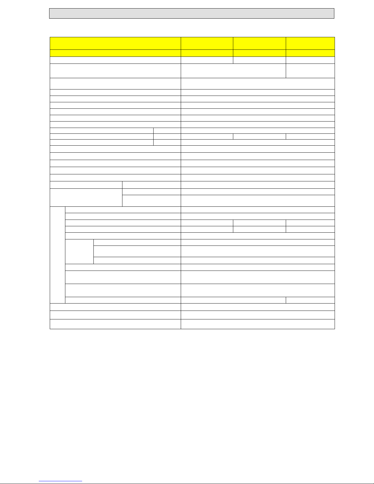
6
Technical and functional characteristics
Tab. 1 Technical characteristics
Name
SIGMA24 TF
EKO MT
SIGMA31 TF
EKO MAX
KPLUS
Type C32SPV24MEFB C32SPV31MEFB C22SPV23MEF
Gas category
II2H3B/P, I2H, I2E+, II2ELL3B/P, II2HS 3B/P,
II2E3P, II2L3B/P
I2H
Flue type Forced
Burning room Sealed
Energy efficiency symbol (dir. 92/42/CEE) ***
Class NOx (natural gas)
3
Energy efficiency class on central heating circuit
C
Energy efficiency class on domestic hot water circuit
A
Clasa CONFORT apa calda menajera (EN13203) **
Thermal efficiency
G20 93 %
Power (min/max) G20 10 – 24 KW 11 – 31 KW 9 – 23 kW
Rated pressure gas input G20
20 mbar
Pressure (min/max) on thermal circuit 0.5÷3.5 bar
Maximum pressure on DHW circuit 8 bar
Temperature on thermal circuit 30÷80 °C
Temperature on the floor heating system circuit 15-45 °C
Temperature on domestic hot water circuit 35÷55 °C
Hot water flow
∆ t = 30 °C
10 l/min
Electric characteristics
Input
~230VAC/50 Hz
Rated power
(
EEI
pump <0,2)
80 W
Construction characteristics
Height
700 mm
Width
436 mm
Depth
306 mm 328 mm 306 mm
Weight
32 kg
36 kg
32 kg
Capacity primary heat switch 1 l
Conectors
Thermal input, output 3/4‘’
Cold water input, hot water output 1/2'’
Gas input 3/4'’
Expansion vessel with membrane
7 l
Air/ gas incoming/ outgoing pipes
Co-axial - Ø100/Ø60,
Dual - Ø80 **
Length of burnt gases connecting pipe
Co-axial - maxim 3 m,
Dual - maxim 5 m **
Evacuation type
C12, C22, C32, C42, C52, C62, C72, C
82
C12, C22, C
82
Burnt gases (maximum temperature) ~150 °C
Classes of electric protection Class I
Protection class IP 40
** The boiler is standard delivered with 1m co-axial flue.
USER MANUAL CENTRAL HEATING STATION TYPE C32SPV24MEFB; C32SPV31MEFB; C22SPV23MEF
REV.12.06.2017
5 of 19
7
Mounting
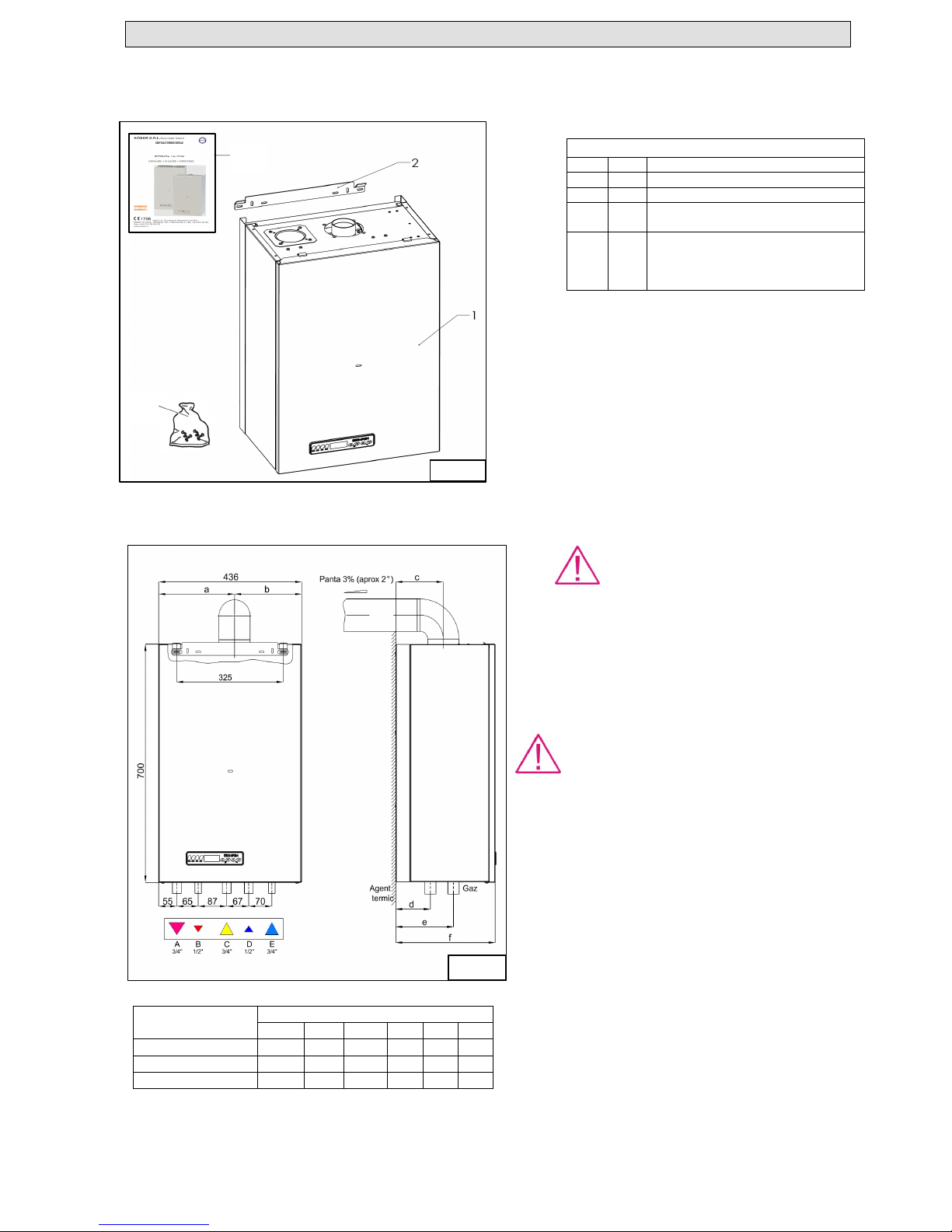
7.1 Mounting set
Check whether the mounting set is complete and undamaged – see table 2.
7.2 Dimensions and mounting positions
7.2.1 Installation site
When choosing the installation site, please take into consideration the following safety instructions:
Caution!
Do not install the station in spaces that are
exposed to freezing! In case of freezing the sation can be
damaged.
This equipment can not be installed and used in open air.
Outdoor installation can cause functioning flaws.
Caution!
It is not recommended to install the central heating station
in bathrooms or kitchens or other areas with high humidity.
The station can be installed only in rooms with maximum
60% humidity between 20-30°C in order to prevent the
damaging of electronic components.
Caution!
The burning air of the station must not contain
substances such as flourine vapours, chlorine, sulphur,
dissolvants, colorants, adhesives or gasoline. These
substances can lead in time to the corrosion of the
equipment and air/ gas incoming/ outgoing pipes.
Legend:
A – Thermal input connector
B – Hot water output connector
C - Fuel input connector
D - Cold water input connector
E - Thermal output connector
Fig. 1.2 Dimensions and mounting positions
Tab. 2 Mounting set
Pos.
Item
Name
1 1 Station
2 1 Station support
3 1
Bag of small elements - it contains:
- mounting screws 8x80 - 2 items.
4 1
Printed packet – it contains:
- user manual - 1 item
- conformity statement - 1 item
- warranty certificate – 1item
Model
Dimensions (mm)
a b c d e f
C32SPV24MEFB
231 205 145 107 176 306
C22SPV23MEF 231 205 145 107 176 306
C32SPV31MEFB 271 165 168 129 197 328
Fig. 1.2
3
4
Fig.1.1
USER MANUAL CENTRAL HEATING STATION TYPE C32SPV24MEFB; C32SPV31MEFB; C22SPV23MEF
REV.12.06.2017
6 of 19
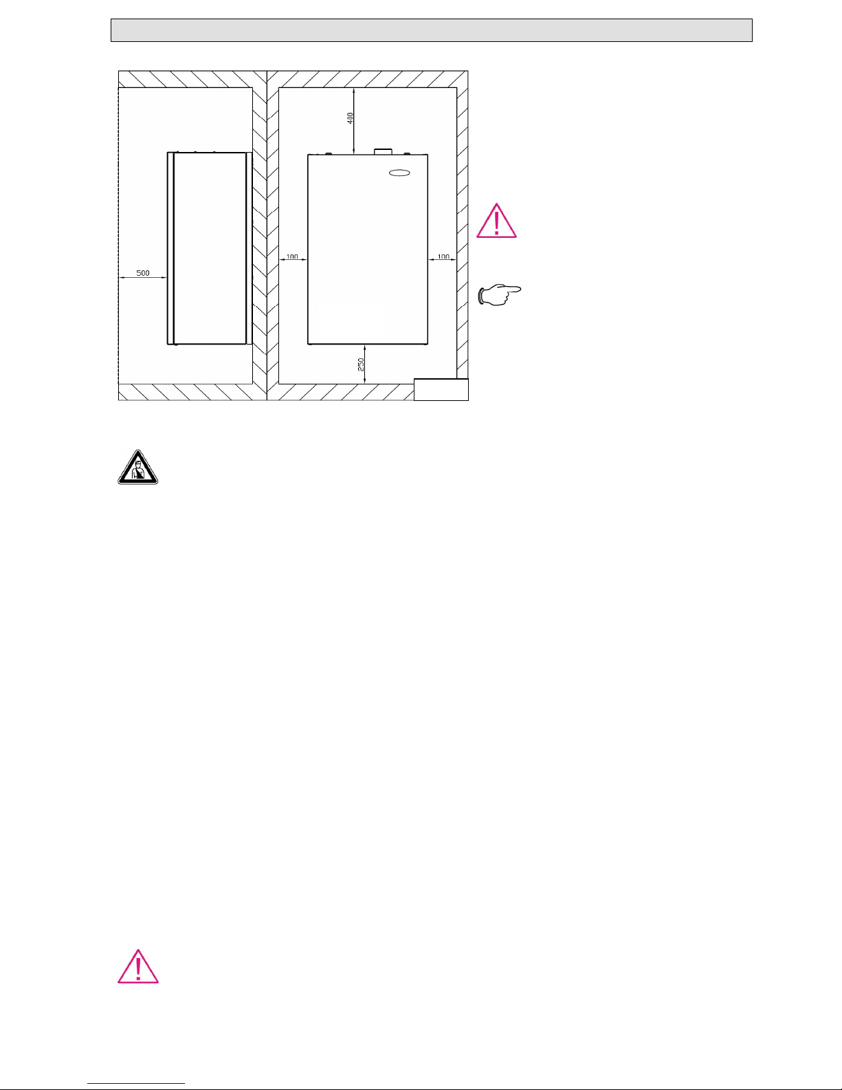
7.2.2 Minimum necessary distances/ free spaces for mounting
Both for the mounting/ installation of the central
heating stations and for later maintenance operations
you will need the following minimum distances (fig.
1.3), respectively minimum free spaces for mounting:
– distance to the lateral: 100 mm
– distance to the bottom part: 250 mm
– distance to the upper part: 400 mm
- distance to front part: 500mm
Caution!
Danger of damaging the equipment by
incorrect setting!
The equipment can be mounted only on a flat, fixed
surface.
Note!
Minimum necessary distances/ free spaces
for mounting are valid also for mounting
with/ within pieces of furniture.
8
Installation
Danger!
Danger of death by poisoning and explosion because of breeches in the gas pipes and connections in case of
incorrect installation!
Installation and commissioning can be done only by a company authorized and agreed by KÖBER SRL-Vaduri
Branch!
This company will assume responsibility for the correct installation and commissioning.
8.1 Conditions for the installation of the central heating station
8.1.1 Installation directions
The central heating station will be subject to corrosion from the moment it is filled with water!
To receive warranty during the entire warranty period it is essential to take into consideration the following directions in order
not to increase the corrosion!
- The burning gas must have the sulphur content within the limits of the applicable European standard: it is accepted for a short
period of time to have a maximum of 150 mg/m3, but the yearly average must be of 30 mg/m3.
- The burning air must not contain chlorine, ammonia, alkaline agents, halogenated hydrocarbs, freon, plaster particles, lints,
dirt or dust;
- Installation of the central heating station in the proximity of a swimming pool, washing machine or cleaner can result in the
contamination of the burning air with these compounds.
- Water pH must be within the following limits: 7,5<pH<9,5
- It is recommended to check the water and thermal agent pH frequently and if the value does not fall within the limits provided
by the manufacturer, it will be treated again.
- Water asperity must be within the limits 5°F <TH <15°F (5°F (French degrees), equivalent to 50 mg CaCO3 or an equivalent
quantity of other Ca and Mg salts).
- It is recommended to have repeated station startup cycles with the fuel tap off in order to air the installation.
- If the central heating station is not used for a long period of time during the cold season, full emptying of the installation is
recommended to prevent damage caused by freezing.
8.1.2 Protection of the station in order to keep the warranty
Before and during installation, the central heating station must be kept away from impurities: construction dust, sand, copper
dust, fats etc as well as welding splashes, scoria. In any of theses cases, the installation must be washed with clean water mixed
with a highly concentrated cleaning agent.
Genereally, in order to keep the warranty it is necessary to apply any neccesary treatment to prevent the contamination of
water with the following:
Black mud (magnetite - Fe3O4) formed as a result of the continuous electrolyte corrosion occurring in any installation
which is not protected with an inhibitor.
Red mud (rust - Fe2O3) produced during oxidation.
Calcarous deposits produced especially on the hottest areas of the central heating station.
A combination of these three factors mentioned above causes the majority of the problems occurring with heating systems.
Caution!
The presence of these substances (black mud/ red mud/ calcarous deposits) means that the standard measures to
prevent problems of the heating system were not observed. This is one of the causes resulting in losing warranty!
Fig. 1.3
 Loading...