

Kober C38GC25, C38GC35-CH1, C38GC25-P, C38GC35, C38GC29 User Manual
...
18
KÖBER SRL VADURI BRANCH
USER MANUAL
CONDENSING GAS BOILER
C38GC25 C38GC29 C38GC35
C38GC25-P C38GC35-CH1 C38GC35-CH2
Image for presentation only. Product
may look slightly different depending
on the area and the purchase period.
KÖBER Ltd, no. 25 Vaduri, Alexandru cel Bun Commune, Neamt 617511, Romania
Tel.:+40.233.24.17.46, 233.24.19.33, Fax:+40.233.24.19.29
www.motan.ro
2726
P M0 0 2 2 7 3

USER MANUAL CENTRAL HEATING BOILER TYPE C38GC25; C38GC25-P; C38GC29; C38GC35; C38GC35-CH1; C38GC35-CH2
Contents
1 Safety instructions and symbols ................................................................................................................................................... 4
1.1 Valability of instructions ......................................................................................................................................................................... 4
1.2 CE Marking .............................................................................................................................................................................................. 4
1.3 Use according to destination ............................................................................................................................................................... 4
2 Technical and functional characteristics .................................................................................................................................... 5
2.1 Structure ................................................................................................................................................................................................... 5
2.1.1 Structure of boiler type C38GC25 / C38GC29 / C38GC35........................................................................................ 5
2.1.2 Structure of boiler type C38GC25-P .............................................................................................................................. 6
2.1.3 The structure of condensation mural central heating gas boilers C38GC35-CH1 .................................................... 7
2.1.4 The structure of condensation mural central heating gas boilers C38GC35-CH2 .................................................... 8
2.2 Constructive and functional characteristics ...................................................................................................................................... 9
3 Safety instructions ........................................................................................................................................................................ 12
3.1 Instalation and adjustment ................................................................................................................................................................. 12
3.2 Gas smell ................................................................................................................................................................................................ 12
3.3 Changes in the area adiacent to the heating BOILER .................................................................................................................. 12
4 Mounting ...................................................................................................................................................................................... 12
4.1 Mounting set.......................................................................................................................................................................................... 12
4.2 Dimensions and mounting positions .................................................................................................................................................. 13
4.2.1 Installation site .................................................................................................................................................................. 13
4.2.2 Minimum necessary distances/ free spaces for mounting ....................................................................................... 15
4.2.3 Installing the boiler ........................................................................................................................................................... 15
5 Installation .................................................................................................................................................................................... 16
5.1 Conditions for the installation of the central heating BOILER ........................................................................................................ 16
5.1.1 Installation indication ...................................................................................................................................................... 16
5.1.2 Protection of the BOILER in order to keep the warranty ........................................................................................... 16
5.2 Gas connecting pipe .......................................................................................................................................................................... 16
5.3 General directions for the heating installation ................................................................................................................................ 16
5.4 General directions for the hot water circuit ..................................................................................................................................... 17
5.5 Connecting pipe of the condensation output duct ...................................................................................................................... 17
5.6 Connecting pipe of the safety valve ................................................................................................................................................ 18
5.7 Air inlet pipe / burnt gases outlet pipe ............................................................................................................................................. 18
5.8 Electric grid connection ...................................................................................................................................................................... 18
6 Operation instructions ................................................................................................................................................................. 19
6.1 Control Panel LMC1X for boiler types C38GC25, C38GC29, C38GC35 ...................................................................................... 19
6.2 Description of functions and graphic contexts displayed by the control panel LMC1X
6.2.1 Graphical context - Display the E88 error .................................................................................................................... 20
6.2.2 Graphic context
6.2.3 LIGHT function control panel LMC1X ............................................................................................................................ 20
6.2.4 Graphic context - Stand-by control panel LMC1X ..................................................................................................... 20
6.2.5 Graphic context – on hold (ON) control panel LMC1X ............................................................................................. 20
6.2.6 Graphic context – user menu control panel LMC1X ................................................................................................. 21
6.2.7 Graphic context – SERVICE submenu control panel LMC1X .................................................................................... 21
6.2.8 Graphic context – ECONOMIC submenu control panel LMC1X ............................................................................. 21
6.3 Control Panel
Table 5: Control panel keys
6.3.1
6.3.2 Graphical context - Display the E88 error .................................................................................................................... 22
6.3.3
6.3.4
6.3.5
6.3.6
6.3.7
6.3.8
6.3.9
7 COMMISSIONING ........................................................................................................................................................................ 24
7.1 Commissioning work ............................................................................................................................................................................ 24
7.2 Starting the boiler and choosing the operating mode: ................................................................................................................. 24
7.2.1
7.2.2
7.2.3
7.2.4 Domestic hot water operation via an individual boiler connected to the boiler (see chapter 11 '' Operating
modes '') 25
7.2.5 Functioning as heating BOILER (HS) .............................................................................................................................. 25
7.2.6 Preset functions related to BOILER safety .................................................................................................................... 25
7.3 BOILER switch off in safety conditions ............................................................................................................................................... 25
7.4 User training ........................................................................................................................................................................................... 26
7.5 Quality Conditions and Warranty ...................................................................................................................................................... 26
8 INSPECTION AND MAINTENANCE................................................................................................................................................ 26
8.1 Inspection and maintenance intervals ............................................................................................................................................. 26
8.2 Maintenance works ............................................................................................................................................................................. 27
9 Error signals .................................................................................................................................................................................. 27
10 Drawings necessary for mounting and installation ................................................................................................................... 29
LMC1112-15
Description of functions and of graphic contexts diplayed on the control panel LMC1112
LIGHT function control panel LMC1112
Graphic context – station startup control panel LMC1112
Graphic context - Stand-by control panel LMC1112
Graphic context – error state control panel LMC1112
Graphic context – waiting state control panel LMC1112
Graphic context – functioning state control panel LMC1112
Graphic context – adjustment of functioning parameters control panel LMC1112
Starting
Choosing the functioning modes of the central heating BOILER
Functioning
the boiler (control panel LMC1X and control panel LMC1112) ................................................................ 24
– switching the boiler on
for boiler versions C38GC25-P, C38GC35-CH1, C38GC35-CH2 .................................................. 22
........................................................................................................................................................................ 22
as domestic hot water BOILER (DHW) ................................................................................................... 24
control panel LMC1X .......................................................................... 20
..................................................................................................................... 22
.................................................................................. 23
............................................................................................ 23
......................................................................................... 23
.................................................................................... 23
............................................................................. 23
....................................................................... 24
.................................................. 20
...................... 22
.................................... 23
REV. 01.07.2019
2 din 37

USER MANUAL CENTRAL HEATING BOILER TYPE C38GC25; C38GC25-P; C38GC29; C38GC35; C38GC35-CH1; C38GC35-CH2
11.2. Minimum distances recommended for the mounting of the co-axial kit ................................................................................... 29
11.3. Hydraulic characteristic of pump ...................................................................................................................................................... 30
11.4. Functioning schemes covered by warranty .................................................................................................................................... 31
11.4.1 Radiators heating and instant preparation of hot water ..................................................................................................... 31
11.4.2 Underfloor heating and instant preparation of hot water, .................................................................................................. 31
11.4.3 Radiators heating and accumulated preparation of hot water (accummulation water tank) ................................... 32
11.4.4 Underfloor heating and accumulated preparation of hot water (accummulation water tank) ................................. 32
11.4.5 Radiators heating, C38GC35-CH2 boiler (without V3C valve, only with heating circuit preparation) ........................ 33
11.4.6 Underfloor heating, C38GC35-CH2 boiler (without V3C valve, only with heating circuit preparation) ...................... 33
11.4.7 Raditors and underfloor heating and external boiler for DHW, C38GC35-CH2 boiler .................................................... 34
11.4.8 Raditors heating and external boiler for DHW, C38GC35-CH2 boiler ................................................................................ 34
11.4.9 Underfloor heating and external boiler for DHW, C38GC35-CH1 boiler ............................................................................ 35
11.4.10 Combine radiators and underfloor heating and external boiler for DHW, C38GC35-CH1 boiler ............................... 35
11.4.11 Radiators heating, external boiler for DHW and solar panel, C38GC35-CH1 boiler...................................................... 36
11.4.12 Underfloor heating, external boiler for DHW and solar panel, C38GC35-CH1 boiler .................................................... 36
11.4.13 Combine radiators and underfloor heating, external boiler for DHW and solar panel, C38GC35-CH1 boiler ......... 37
REV. 01.07.2019
3 din 37
USER MANUAL CENTRAL HEATING BOILER TYPE C38GC25; C38GC25-P; C38GC29; C38GC35; C38GC35-CH1; C38GC35-CH2
1
Safety instructions and symbols
When installing the central heating BOILER we ask you to respect the safety instructions contained in this manual!
This manual is the property of KÖBER SRL-Vaduri branch. Copying or reproduction without written consent KÖBER SRL-Vaduri
branch is strictly forbidden.
The following lines explain the symbols used in the text:
Danger!
–
direct danger for corporal integrity and life.
Danger!
Caution!
Note!
–
danger of death by electrocution.
–
pontentially dangerous situation for the product and the environment.
–
useful notes and information. This symbol indicates a necessary activity.
1.1 Valability of instructions
These instructions are valid exclusively for central heating boilers models:
BOILER TYPE NAME POWER FUNCTIONS PARTICULARITY
C38GC25 MKDENS25 25 kW DHW + CENTRAL HEATING BRASS HYDRAULIC GROUP
C38GC29 MKDENS29 29 kW DHW + CENTRAL HEATING
C38GC35 MKDENS35
C38GC25-P MKDENS25-P 25 kW DHW + CENTRAL HEATING PA66GF30 HYDRAULIC GROUP
C38GC35-CH1 MKDENS35 TERMOV
C38GC35-CH2 MKDENS35 TERMO
Where:
C38 – internal name;
G – type of fuel-gas;
C – compensating;
25, 29 and 35 - t
P/CH1/CH2 - constructive versions
The boilers are designed to use gas from classes: I2H
The type of gas for which the device is adjusted is specified on the product label and nameplate.
1.2 CE Marking
in the applicable European legislation:
- Directive regarding gas equipment 2009/142/CE (ex. 90/396/CEE)
- EcoDesign Directive 2009/125/EC
- Directive regarding energy efficiency 92/42/EEC and European Regulations no.811-814/2013
- Directive regarding electromagnetic compatibility 2004/108/EC (ex. 89/366/CEE)
- Directive for low frequency 2006/95/EC (ex. 73/23/EEC).
1.3 Use according to destination
-
Central heating boilers C38GC25, C38GC29, C38GC35 are designed following current technical standards and observing
recognized safety norms
- In case of misuse or inappropriate use, the health or life of users or third parties can be put in danger, as well as the central
heating BOILER and other goods;
- This equipment must not be used by people with limited psychological and sensitive capacities (including children), or by
people with no experience or/ and no knowledge;
- The BOILER provides both heating in closed circuit central heating installations, as well as hot water. Use for other purposes or for
additional purposes other than stipulated is considered inappropriate use. The manufacturer is not responsible for possible
damage resulting from inappropriate use.
- Compliance with the use and installation instructions, the additional documentation, as well as with the inspection and
maintenance stipulations is part of what is understood by use according to destination.
he maximum rated power which the boiler can supply
CE marking applied on this product guarantees that the equipment complies with the esential conditions stipulated
;
35 KW
35 KW
35 KW
The user is the only one responsible;
DHW + CENTRAL HEATING
CENTRAL HEATING V3C INCLUDED
CENTRAL HEATING WITHOUT V3C
, in kW
BRASS HYDRAULIC GROUP
BRASS HYDRAULIC GROUP
REV. 01.07.2019
4 din 37

USER MANUAL CENTRAL HEATING BOILER TYPE C38GC25; C38GC25-P; C38GC29; C38GC35; C38GC35-CH1; C38GC35-CH2
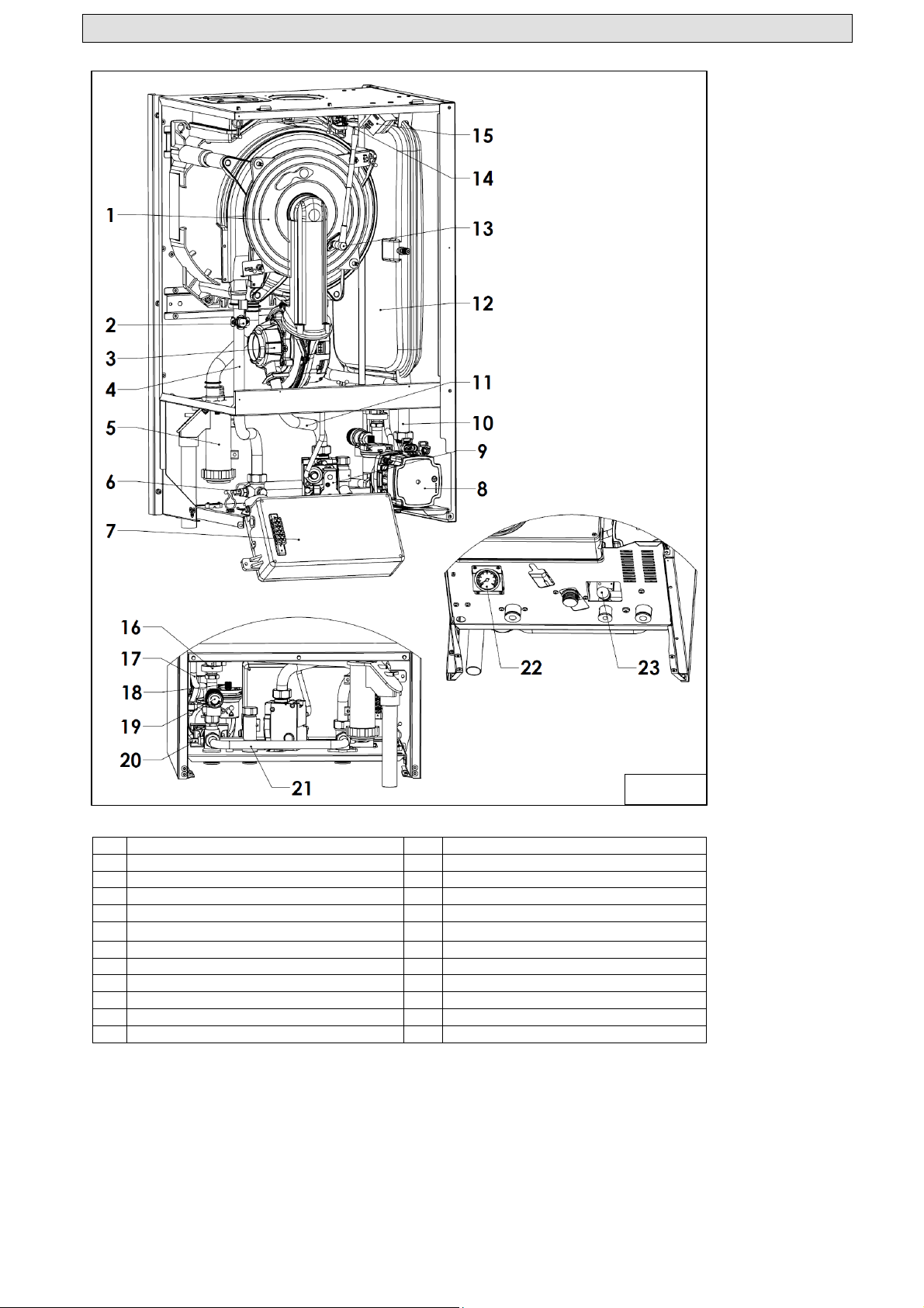
Figure
2
Technical and functional characteristics
2.1 Structure
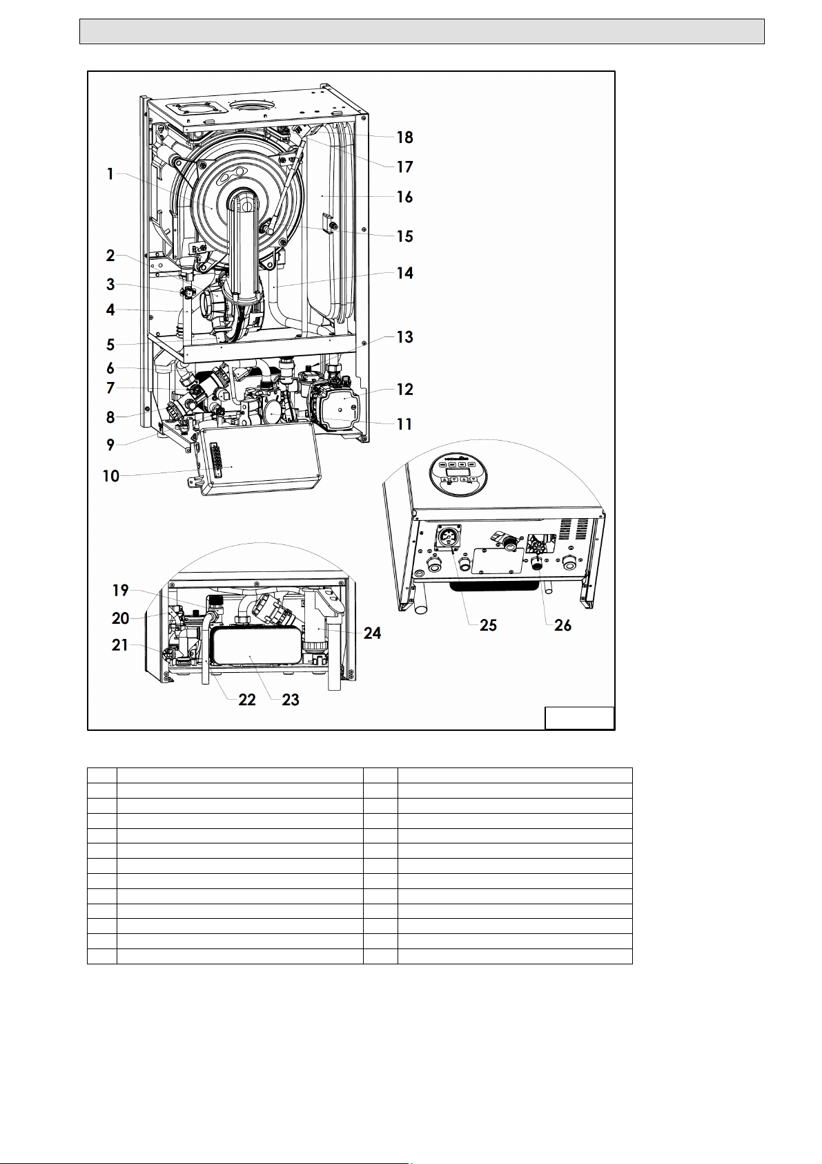
2.1.1 Structure of boiler type C38GC25 / C38GC29 / C38GC35
(*) The boiler in the
standard configuration
is not delivered
equipped with
landmarks from pos. 14.
Equipping the boiler
with those landmarks
can be done by the
producer only by
request.
Tab. 2.1 Components of the condensing boiler
1 Main heat exchanger 15 Ignition electrode
2 Built-in fan nozzle 16 Expansion vessel
3 Over-temperature thermostat 17 Flue gas temperature sensor
4 Heating tour connection 18 Ignition transformer
5 Gas supply connection 19 Pressure relief valve 3 bar
6 3-way valve actuator 20
7 Heating temperature sensor 21
8 Domestic hot water temperature sensor 22
9 Electronic box 23
10 Gas valve 24
11 Pump 25
12 Pump automatic air vent 26 Pressure gauge
13 Heating return connection 27 Filling tap
14* Flow switch
Expansion vessel connection
Return heating temperature sensor
Water pressure sensor
Pressure valve connection
Secondary heat exchanger
Drain trap for condense
REV. 01.07.2019
5 din 37
USER MANUAL CENTRAL HEATING BOILER TYPE C38GC25; C38GC25-P; C38GC29; C38GC35; C38GC35-CH1; C38GC35-CH2
Figura 2.1
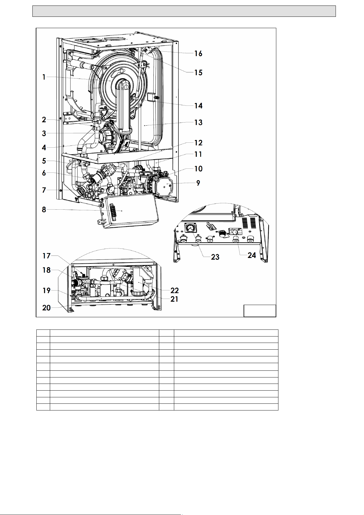
2.1.2 Structure of boiler type C38GC25-P
Tab. 2.1 Components of the condensing boiler
1 Main heat exchanger 14 Heating return connection
2 Built-in fan nozzle 15 Ignition electrode
3 Over-temperature thermostat 16 Expansion vessel
4 Heating tour connection 17 Flue gas temperature sensor
5 Gas supply connection 18 Ignition transformer
6 3-way valve actuator 19 Pressure relief valve 3 bar
7 Heating temperature sensor 20 Expansion vessel connection
8 Water pressure sensor 21
9 Domestic hot water temperature sensor 22
10 Electronic box 23
11 Gas valve 24
12 Pump 25
13 Pump automatic air vent 26 Filling tap
REV. 01.07.2019
Return heating temperature sensor
Pressure valve connection
Secondary heat exchanger
Drain trap for condense
Pressure gauge
6 din 37
USER MANUAL CENTRAL HEATING BOILER TYPE C38GC25; C38GC25-P; C38GC29; C38GC35; C38GC35-CH1; C38GC35-CH2
2.1.3 The structure of condensation mural central heating gas boilers C38GC35-CH1
Fig. 2.1
Tab.2.1 Components of the condensation mural central heating gas boiler
1 Main heat-exchanger 13 Expansion vessel
2 Primary circuit over-temperature thermostat 14 Ignition electrode
3 Fan with built-in nozzle 15 Flue gas temperature sensor
4 Heating tour connection 16 Ignition transformer
5 3-way valve actuator 17 Automated air vent
6 Heating temperature sensor 18 Pressure relief valve 3 bar
7 Water pressure sensor 19 Return heating temperature sensor
8 Electronic box 20 By-pass connection
9 Circulation pump 21 Return heating boiler
10 Gas valve 22 Drain trap for condense
11 Heating return connection 23 Pressure gauge
12 Gas supply connection 24 Filing tap
REV. 01.07.2019
7 din 37
USER MANUAL CENTRAL HEATING BOILER TYPE C38GC25; C38GC25-P; C38GC29; C38GC35; C38GC35-CH1; C38GC35-CH2
Fig.
2.1.4 The structure of condensation mural central heating gas boilers C38GC35-CH2
Tab.2.1 Components of the condensation mural central heating gas boiler
1 Main heat-exchanger 13 Ignition electrode
2 Primary circuit over-temperature thermostat 14 Flue gas temperature sensor
3 Fan with built-in nozzle 15 Ignition transformer
4 Heating tour connection 16 Water pressure senzor
5 Drain trap for condense
6 Heating temperature sensor 18 Automated air
7 Electronic box 19 Pressure relief valve 3 bar
8 Circulation pump 20 Return heating temperature sensor
9 Gas valve 21 By-pass connection
10 Heating return connection 22 Pressure gauge
11 Gas supply connection 23 Filing tap
12 Expansion vessel
17 Expansion vessel connection vent
REV. 01.07.2019
8 din 37
USER MANUAL CENTRAL HEATING BOILER TYPE C38GC25; C38GC25-P; C38GC29; C38GC35; C38GC35-CH1; C38GC35-CH2
2H (GN
-
G20)
with flow
Nominal power
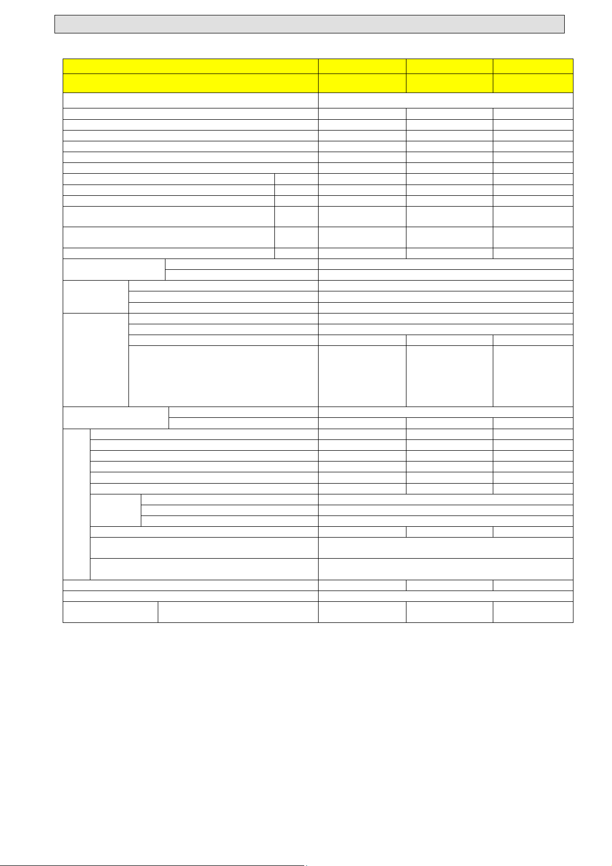
2.2 Constructive and functional characteristics
Tab.1 Technical characteristics C38GC25, C38GC29, C38GC35
Commercial name MKDENS25 MKDENS35 MKDENS35
Type
Gas category to be used
Flue type Forced Forced Forced
Burning room Condensing Condensing Condensing
Efficiency stars (dir. 92/42/CEE) **** **** ****
Nox class 5 5 5
Heating energy efficiency class A A A
DHW energy efficiency class A A A
Min/Max CH power (kW) kW 2,8/26,7 3,0/30.6 3,5/33,9
Max power 80/60 (kW) kW 25,6 28,3 32,8
Max power 50/30 (kW) kW
Output performance at nominal heat input at
80/60 °C (PCI) (%)
Output performance at nominal heat input at
50/30 °C (PCI) (%)
Consum nominal maxim de combustibil mc/h 2,82 3,24 3,59
Gas pressure
Heating
circuit
DHW circuit
Electrical
characteristics
Height
Width
Depth
Height with installed elbow 850 mm
Pimary heat exchanger capacity ~35 kg
Height
Connec
tors
Expansion vessel with membrane
Evacuation type
Caracteristici constructive
Dimensions flue type
Flue temp. (50/30 °C) ~59 °C
Protection class Class IP40
Informative values:
(*)-The standard gas boiler is delivered flow restrictor of 12l/min
(**)-The standard gas boiler is delivered with dual coaxial kit as accessory; dual kit is delivered as accessory on demand
REV. 01.07.2019
Maximum pressure on the hot water circuit minim 0,8 bar - maxim 3 bar
Temperature adjustment interval radiators 30÷80 °C
Temperature adjustment interval underfloor 15÷45 °C
Temperature adjustment interval 30÷60 °C
Temperature adjustment interval-boiler mode 70 °C
DHW Confort EN 13203 ***
Hot water flow at ∆ t = 30 °K
* flow restrictor 12l/min
GN (on the regulator) 20 mbar (max. 25 mbar, min. 17 mbar)
GN max 35 mbar
Power ~230VAC/50 Hz
Thermal input, output 3/4‘’
Cold water input, hot water output 1/2'’
Gas input 3/4'’
Maximum water capacity in central
heating installation
%
% 106 106 106
C38GC25 C38GC35 C38GC35
I
28,2 32,4 35,8
97 97 97
12 l/min with flow
restrictor *
13,5 l/min without
flow restrictor *
81 W
713 mm
415 mm
330 mm
~1,4 l
7 l
B23; B33; C13; C13x; C23; C23x; C33; C33x; C43; C43x; C53;
C53x; C63; C63x; C73; C73x; C83; C83x; C93; C93x
Lenght for coaxial flue D60/D100: min. 1m - max. 20m**
Lenght for dual flue D80/D80: min. 1m - max. 20m
*** ***
12 l/min with flow
restrictor *
15,7 l/min without
flow restrictor *
81W
713 mm
415 mm
390 mm
860 mm
~36 kg
~1,6 l
7 l
~49 °C ~69 °C
200 l 200 l 200 l
12 l/min
restrictor *
17 l/min without
flow restrictor *
81 W
713 mm
415 mm
390 mm
860 mm
~36 kg
~1,8 l
7 l
9 din 37
USER MANUAL CENTRAL HEATING BOILER TYPE C38GC25; C38GC25-P; C38GC29; C38GC35; C38GC35-CH1; C38GC35-CH2
2H (GN
-
G20)
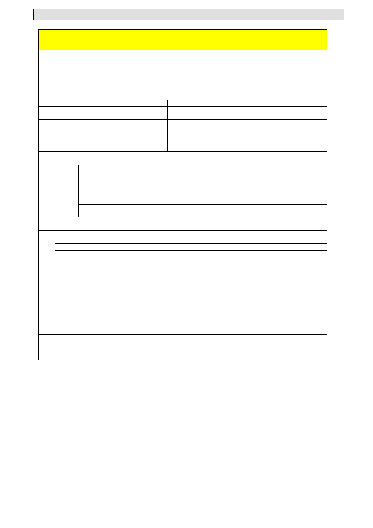
Tab.1 Technical characteristics C38GC25-P
Commercial name MKDENS25
Type
Gas category to be used
Flue type Forced
Burning room Condensing
Efficiency stars (dir. 92/42/CEE) ****
Nox class 5
Heating energy efficiency class A
DHW energy efficiency class A
Min/Max CH power (kW) kW
Max power 80/60 (kW) kW 25,6
Max power 50/30 (kW) kW 28,2
Output performance at nominal heat input at
80/60 °C (PCI) (%)
Output performance at nominal heat input at
50/30 °C (PCI) (%)
Consum nominal maxim de combustibil mc/h 2,82
Gas pressure
Heating
circuit
DHW circuit
Electrical
characteristics
Height
Width
Depth
Height with installed elbow 860 mm
Pimary heat exchanger capacity ~35 kg
Height
Connec
tors
Expansion vessel with membrane
Evacuation type
Dimensions flue type
Caracteristici constructive
Flue temp. (50/30 °C) ~59 °C
Protection class Class IP40
Informative values:
(*)-The standard gas boiler is delivered flow restrictor of 12l/min
(**)-The standard gas boiler is delivered with dual coaxial kit as accessory; dual kit is delivered as accessory on demand
Maximum pressure on the hot water circuit minim 0,8 bar - maxim 3 bar
Temperature adjustment interval radiators 30÷80 °C
Temperature adjustment interval underfloor 15÷45 °C
Temperature adjustment interval 30÷60 °C
Temperature adjustment interval-boiler mode 70 °C
DHW Confort EN 13203 ***
Hot water flow at ∆ t = 30 °K
GN (on the regulator) 20 mbar (max. 25 mbar, min. 17 mbar)
GN max 35 mbar
Power ~230VAC/50 Hz
Nominal power
Thermal input, output 3/4‘’
Cold water input, hot water output 1/2'’
Gas input 3/4'’
Maximum water capacity in central
heating installation
C38GC25-P
I
2,8/26,7
% 97
% 106
12 l/min with flow restrictor *
13,5 l/min without flow restrictor *
81 W
722 mm
415 mm
330 mm
~1,4 l
7 l
B23; B33; C13; C13x; C23; C23x; C33; C33x; C43;
C43x; C53; C53x; C63; C63x; C73; C73x; C83; C83x;
C93; C93x
Lenght for coaxial flue D60/D100: min. 1m - max.
20m**
Lenght for dual flue D80/D80: min. 1m - max. 20m
200 l
REV. 01.07.2019
10 din 37
USER MANUAL CENTRAL HEATING BOILER TYPE C38GC25; C38GC25-P; C38GC29; C38GC35; C38GC35-CH1; C38GC35-CH2
2H (GN
-
G20)
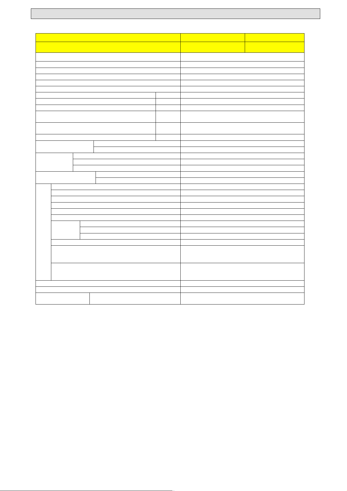
Nominal power
Tab.1 Technical characteristics C38GC25-CH1, C38GC35-CH2
Commercial name C38GC25-CH1 C38GC25-CH2
Type MKDENS35 TERMOV MKDENS35 TERMO
Gas category to be used
Flue type Forced
Burning room Condensing
Efficiency stars (dir. 92/42/CEE) ****
Nox class 5
Heating energy efficiency class A
Min/Max CH power (kW) kW
Max power 80/60 (kW) kW 32,8
Max power 50/30 (kW) kW 35,8
Output performance at nominal heat input at
80/60 °C (PCI) (%)
Output performance at nominal heat input at
50/30 °C (PCI) (%)
Consum nominal maxim de combustibil mc/h 3,59
Gas pressure
Heating
circuit
Electrical
characteristics
Height
Width
Depth
Height with installed elbow 860 mm
Pimary heat exchanger capacity ~36 kg
Height
Connec
tors
Expansion vessel with membrane
Evacuation type
Dimensions flue type
Caracteristici constructive
Flue temp. (50/30 °C) ~59 °C
Protection class Class IP40
Informative values:
(**)-The standard gas boiler is delivered with dual coaxial kit as accessory; dual kit is delivered as accessory on demand
Maximum pressure on the hot water circuit minim 0,8 bar - maxim 3 bar
Temperature adjustment interval radiators 30÷80 °C
Temperature adjustment interval underfloor 15÷45 °C
GN (on the regulator) 20 mbar (max. 25 mbar, min. 17 mbar)
GN max 35 mbar
Power ~230VAC/50 Hz
Thermal input, output 3/4‘’
Cold water input 1/2'’
Gas input 3/4'’
Maximum water capacity in central
heating installation
I
3,5/33,9
% 97
% 106
81 W
722 mm
415 mm
386 mm
~1,8 l
7 l
B23; B33; C13; C13x; C23; C23x; C33; C33x; C43;
C43x; C53; C53x; C63; C63x; C73; C73x; C83; C83x;
C93; C93x
Lenght for coaxial flue D60/D100: min. 1m - max.
20m**
Lenght for dual flue D80/D80: min. 1m - max. 20m
200 l
REV. 01.07.2019
11 din 37
USER MANUAL CENTRAL HEATING BOILER TYPE C38GC25; C38GC25-P; C38GC29; C38GC35; C38GC35-CH1; C38GC35-CH2
3
Safety instructions
3.1 Instalation and adjustment
Installation and commissioning can be done only by a company authorized and agreed by KÖBER SRL-Vaduri Branch!
This company will assume responsibility for the correct installation and commissioning.
Adjustment work, as well as maintenance and repair are allowed to be performed only by a company authorized and agreed
by KÖBER SRL-Vaduri Branch!
3.2 Gas smell
When gas smell appears, take the following into account:
- Do not activate electric switches in the dangerous zone;
- Do not smoke in the dangerous zone;
- Do not use mobile phones in the dangerous zone;
- Turn off the gas tap;
- Air the dangerous zone;
- Notify the gas distribution company.
3.3 Changes in the area adiacent to the heating BOILER
Modifications of the following installations are not allowed:
- The central heating BOILER;
- The gas or water pipes or electric cables;
- Air/ gas incoming/ outgoing pipes.
Danger!
Danger of death by poisoning and explosion because of breeches in the gas pipes and connections in case of
incorrect installation!
Danger of deterioration when inappropriate tools are used. For tightening or unscrewing connection screws use
appropriate wrenches (no box wrenches, extensions etc).
4
Mounting
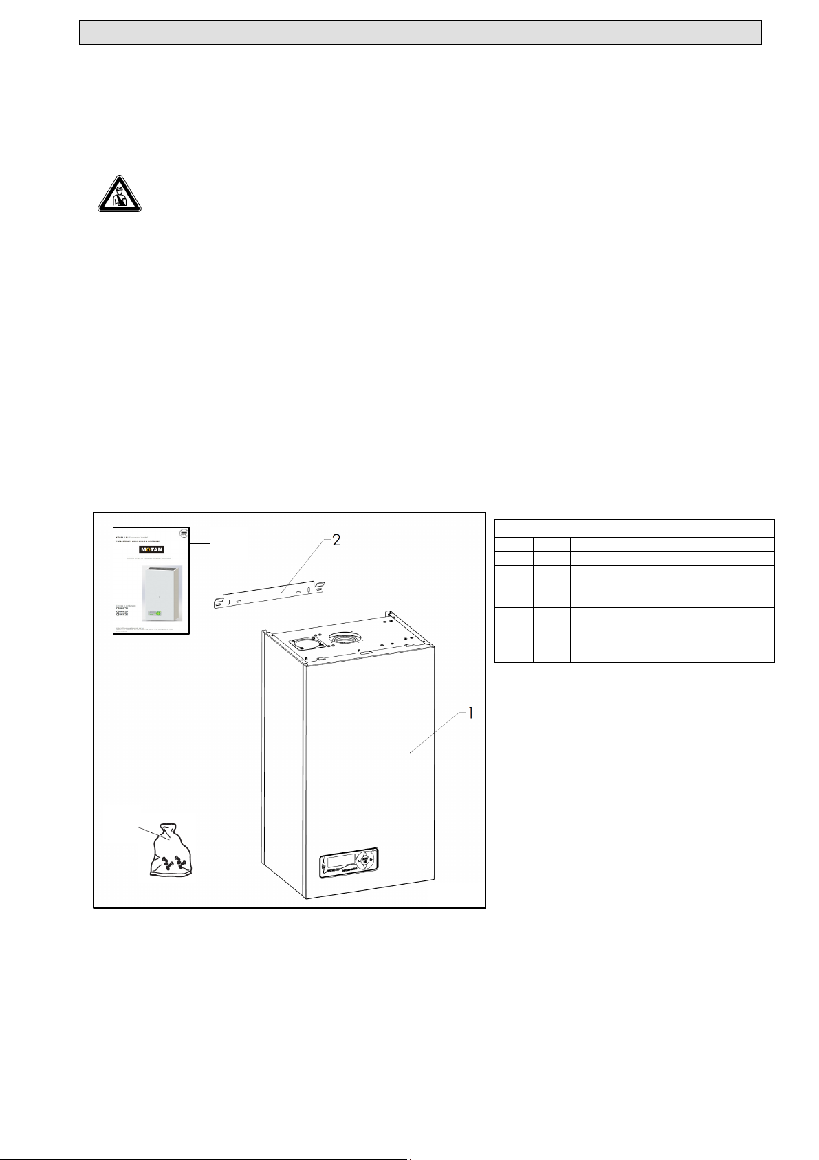
4.1 Mounting set
Check whether the mounting set is complete and undamaged – see table 2.
4
3
Fig. 1.1
Tab. 2 Mounting set
Pcs.
Pos.
1 1 BOILER
2 1 BOILER support
3 1
4 1
Description
Bag of small elements - it contains:
- mounting screws 8x80 - 2 items.
Printed packet – it contains:
- user manual - 1 item
- CE conformity declaration - 1 item
- warranty certificate – 1item
REV. 01.07.2019
12 din 37
 Loading...