

Kobelco SK210LC, SK250-6E User Manual
Kobelco
Dynamic
Acera
Kobelco Construction Machinery America LLC
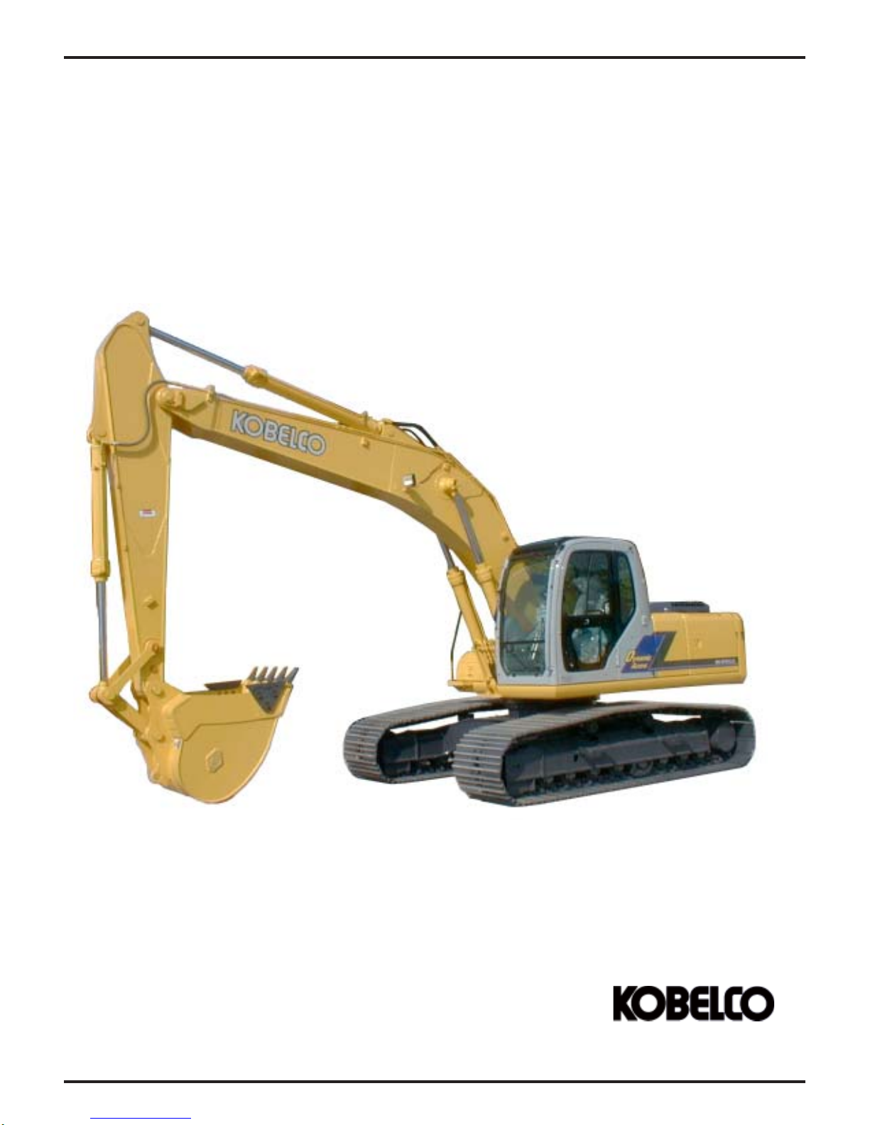
Machine Familiarization
Dynamic Acera 03/05 Rev. 05
Kobelco Construction
Machinery America LLC
Page 3-1
MACHINE FAMILIARIZATION
DYNAMIC ACERA SERIAL NUMBER RANGE
SK160LC YM02U0101 ~
ED190LC YL02U0101 ~
SK210LC YQ07U0101 ~
SK250LC LL08U0101 ~
SK290LC LB03U0101 ~
SK330LC YC06U0101 ~
SK480LC YS06U0101 ~
MINOR CHANGE SERIAL NUMBER RANGE
SK160LC YM03U0522 ~
ED190LC YL03U0136 ~
SK210LC YQ08U0969 ~
SK250LC LL09U0575 ~
SK290LC LB04U0298 ~
SK330LC YC07U0623 ~
Note: Minor Change information is designated
in much of this manual with either the words
“minor change or abbreviation “M/C”.
Page 3-2
Kobelco Construction
Machinery America LLC
Dynamic Acera 03/05 Rev. 05
_
_
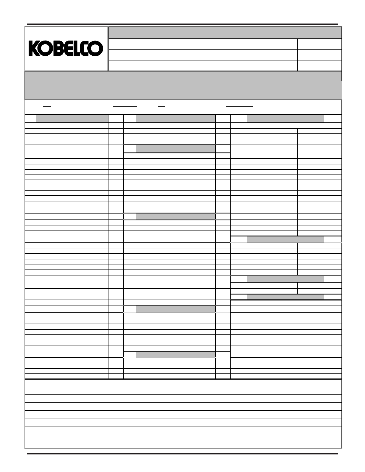
COMPACT, SR, & DYNAMIC ACERA PRE-DELIVERY INSPECTION
_
p
Dealer Name
Address
City State Zip Code:
Dlr. Code Model No.
Serial No.
Hr. Meter
Engine Model _______________________ Engine S/N ___________________________ Bkt. Mfg. _________________________ S/N _________________________
Attachment Type _________________________ Make ______________________ S/N ____________________ Arm Length ___________ Boom Length __________
Arm Cyl. S/N ____________________ Bkt. Cyl. S/N ___________________ Boom Cyl. (L.H.) S/N____________________ Boom Cyl. (R.H.) S/N___________________
Place a "C" in the column if the item is CORRECT. Place a "I" in the column if the item is INCORRECT , and explain by item number under the
comments section. Fill in the blanks provided beside each item.
Visual Checks Miscellaneous
1 Appearance (Overall) 11 40
Good 12 * Display Number
2 Glass * No. 1 Main Cont. P/No.
Dirty Program Version
Broken C/I * No. 2 Eng.Speed Rpm
3 Paint Defects 13 Low Idle (Set Val.)
Cab 14 Engine Coolant Low Idle (Meas. Val)
Upper Frame 15 High Idle (Set Val.)
Lower Frame 16 High Idle (Meas. Val)
Attachments 17 Auto Accel
Counterweight 18 A/S-Mode High Idle
4 Cab 19 B/FC-Mode High Idle
Appearance (Good) 20 * No. 14 C-1 Pump P-1 w/H.L.
Cab Mounting 21 C-1 Pump P-1 w/H.L.
Instrument panels 22 C-1 Pump P-1
Seat assembly 23 C-1 Pump P-1
Cab operation levers C/I C-2 Pump P-2 w/H.L.
Switches / Controls 24 C-2 Pump P-2 w/H.L.
Radio/Speakers C-2 Pump P-2.
Air Cond. / Heating Unit C-2 Pump P-2
Gauge / Warning Lamps 25 C/I
5 Decals 41 Boom Cyl - Out
Misapplied / Damaged 42 Boom Cyl. - In
Wrong/Missing Decal 26 43 Arm Cyl. - Out
6 Hoses,Tubes, Fittings 44 Arm Cyl. - In
Powertrain components 45 Bucket Cyl. - Out
Upper - Loose/Routing 27 46 Bucket Cyl. - In
Lower - Loose/Routing C/I
Attach.- Loose/ Routing 28 47 Swing Speed - LH
7 All Bolts & Fasteners 29 48 Swing Speed - RH
Powertrain components C/I
Upper 49
Lower C/I
Attach. 30 Pilot System Pressure 50
8 Wiring Harness 31 Main Relief w/H.L. *
Routing / Misassembly 32 Main Relief 51
Connections loose 33 Dozer Main Relief *
9 Component Fluid Leakage 34 Swing Port Relief - L
Engine Assembly 35 Swing Port Relief - R
Hyd. Control Valve
Hyd. Main Pump C/I
Hyd. Travel Motor/Red. 36 P1 Main 54
Hyd. Swing Motor/Red. 37 P2 Main
10 Track Adjustment 38 P3 Main
Proper Tension
C/I C/I C/I
Basic Machine Operation Proper
Support Packages
Manual Missing
Parts Missing
Fluid Levels / Lubrication
Engine Oil Level
o
F
Engine Coolant level
Hydraulic Oil Level
Swing Gear Bath
Swing Reduction Unit
Travel Reduction Unit - L.H
Travel Reduction Unit - R.H
Lubricate Attachments
Check Fuel Water Sep.
Check Pilot Filter
Engine Checks
Air Intake/Exhaust Connections
Loose/Misassemble - Connectors
Leaking - Hoses/Tubes/Fittings
Exhaust Connections
Loose/Misassemble - Connectors
Leaking - Hoses/Tubes/Fittings
Fuel System Connections
Loose/Misassemble Connectors
Hoses/Tube/Fitting Leaking
Oil & Fuel Filters
Loose / Leaking
Fan Belt Adjustment
Air Cleaner Elements
Missing
Damaged
Hyd. System.Press. (SK70 ~330)
psi
psi
psi
psi
psi
psi
(
) Note: If applicable for specific machine
*
Hyd. System Press. (Compact Exc.)
psi
psi
psi
39 P4 Main
psi
Service Diagnostic Check
Condition M/H- Mode
Cylinder Cycle Times, M/H-Mode
Swing System Performance
Electrical System
Work & Cab Lights
Inoperable
Swing Flashers
Inoperable
Horn
Inoperable
Pilot Lever Lock Switch
52
Inoperable
53
Travel Alarm
Inoperable
Battery
Electrolyte Level
Charge (Low)
rpm
rpm
rpm
rpm
rpm
rpm
rpm
V
K
V
K
V
K
V
K
Sec
Sec
Sec
Sec
Sec
Sec
Sec
Sec
Comments: (Please enter line item # and Description)
Completed By:_____________________________________ Completed Date:________________
Rev. # 2.0 Form# 00020MIVALL
Dynamic Acera 03/05 Rev. 05
Note:
Please promptly submit this form to the Kobelco
Service Department via mail or the Kobelco Internet
System. For assistance please contact the Kobelco
Service De
t.
Page 3-3

MACHINE FAMILIARIZATION
SK160LC-VI -
The following performance specifications are based on the standard machine with standard attachment.
1. Travel Speed, Swing Speed & Gradeability
DESCRIPTION SPECIFICATION
TRAVEL SPEED 6.0 km per hr (3.7 mph) in mode.
SWING SPEED 11 RPM IN M-Mode / “HI” Idle.
GRADEABILITY 70% (35°) {Limited by engine lubrication}
DRAWBAR FORCE 156 KN (35,100 lbs)
2. Engine
Engine Maker Mitsubishi
Model 4D34-TEG
Type
Number of Cylinders– Bore X Stroke
4.53")
Displacement 3.91 liter (238 cu in.)
Compression Ratio 16.5 : 1
Output Rating 82 kW (111 HP) / 2,200 rpm
Maximum Torque 382 N•m (283 lb-ft)/ 1,800 rpm
Ignition Order 1–3–4–2 CCW Viewed from Flywheel
Injection Timing 16° Before Top Dead Point
Intake Valve Clearance Cold 0.4 mm (0.0157")
Exhaust Valve Clearance Cold 0.4 mm (0.0157")
Electrical System D.C. 24 V
Starting Motor 24 V–5.0 kW
Alternator 24 V–35 A
Batteries 2– 12 V- (136 Ah)
Engine Dry Weight* 403 kg (888 lbs)
Thermostat Begin to open at 76.4°C (169°F).
Cooling Fan Drive Method Ø545mm (Ø21.5") Suction Type Belt
Air Cleaner Dry Type with Safety Elements
3. Hydraulic Components
COMPONENT TYPE
HYDRAULIC PUMPS Tandem, Variable Displacement,
2X143 L/min (2x37.9 Gal/min)
SWING MOTOR Axial Piston
TRAVEL MOTOR Axial Piston
CONTROL VALVES 6 Spool Multiple Control
CYLINDERS (ALL) Double Acting
RETURN FILTER Safety Valve containing Filter Type
OIL COOLER Air Cooled
4. Operating Pressures
PILOT SYSTEM 50 (710)
IMPLEMENT 350 (4980)
SWING 285 (4050)
TRAVEL 350 (4980)
POWER BOOST/HEAVY LIFT 385 (5470)
PERFORMANCE SPECIFICA TIONS
4.0 km per hr (2.5 mph) in mode.
4-Cycle, Water Cooled, Direct
Injection with Turbocharger , Diesel
4–104 mm X 115 mm (4.09" X
Full open at 90°C (194°F).
Drive Pulley Ratio : 0.85
*Less flywheel and electrics.
Axial Piston with Pilot Gear Pump.
Kgf/cm2 (psi)
MACHINE & COMPONENT WEIGHTS
The following weight specifications are based on
the standard machine with standard attachment.
Unit: Kg (lb)
COMPONENT SK160LC-VI
COMPLETE MACHINE (STANDARD) 16,700 (36,800)
UPPER FRAME ASSEMBL Y
UPPER FRAME + COV & GUARDS 1,831 (4,037)
COUNTERWEIGH 3,007 (6,629)
CAB + ELECT + PANEL + SEAT + AC 415 (915)
*BOOM CYLINDER + lower pins 165 (322) X 2
*ENGINE + MUFFLER + ACCESS 431 (950)
RADIA TOR & OIL COOLER 75 (165)
PUMP ASSEMBLY + COUPLER 108 (198)
CONTROL V AVE 250 (551)
*FUEL T ANK 99 (218)
*HYDRAULIC TANK 102 (225)
SWING MOTOR & REDUCTION UNIT
HYDRAULIC PIPES & HOSES 316 (697)
LOWER FRAME ASSEMBL Y
FRAME + Guides + Covers + Piping 2,162 (4,766)
SLEWING RING ASSY 218 (481)
TRAVEL MOTOR & REDUCTION UNIT
TRACK TENSION + IDLERS 210 (463) X2
LOWER ROLLER ASSEMBL Y 35 (77) X14
UPPER ROLLER ASSEMBL Y 17 (37) X4
SPROCKET 72 (159) X2
SWIVEL JOINT 30 (66)
TRACK LINK W/ 600mm (23.6") SHOES
ATT ACHMENT (STANDARD) 2,638 (5,816)
BUCKET ASSEMBL Y [0.52m3 (0.68 yd3)]
ARM ASSEMBL Y
ARM [3.10 m (10’-2”)] 564 (1,340)
*BUCKET CYL + 2 PINS 142 (313)
IDLER LINKS 32 (71)
BUCKET LINK 65 (143)
PINS (4- for bucket, & links)
BOOM ASSEMBL Y 1,411 (3,11 1)
BOOM + Cyl. pin + Foot pin 1,176 (2,593)
*ARM CYLINDER + 2 PINS 215 (474)
PIN (Mounting the Arm) 20 (44)
FLUIDS 311 (686)
HYD OIL 139 (306)
ENG OIL 14 (31)
FUEL 139 (306)
WATER 19 (42)
BOLTS & OTHEER 291 (642)
[3.10 m (10’-2”)]
6,852 (15,106)
204 (450)
6,608 (14,568)
217 (478) X2
1,321 (2,912) X2
370 (816)
857 ( 1,889 )
54 (119)
* DRY WEIGHT
WARNING
USE ONLY LIFTING DEVICES AND EQUIPMENT
WITH RA TED CAPACITIES SUFFICIENT T O LIFT THE
SPECIFIC COMPONENT(S) BEING REMOVED OR
INSTALLED.
Page 3-4
Dynamic Acera 03/05 Rev. 05
MACHINE FAMILIARIZATION
ED190 -
DESCRIPTION SPECIFICATION
TRAVEL SPEED 6.0 km per hr (3.7 mph) in
SWING SPEED 11 RPM IN M-Mode / “HI” Idle.
GRADEABILITY 70% (35°) Limited by engine lubrication
DRAWBAR FORCE 189 KN (42,556 lbs)
Engine Maker Mitsubishi
Model 4D34-TEG
Type
Number of Cylinders : 4 – Bore X Stroke
Displacement 3.91 liter (238 cu in.)
Compression Ratio 16.5 : 1
Output Rating 82 kW (11 1 HP) / 2,200 rpm
Maximum Torque 382 N•m (283 lb-ft)/ 1,800 rpm
Ignition Order 1–3–4–2 CCW Viewed from Flywheel
Injection Timing 16° Before Top Dead Point
Intake Valve Clearance Cold 0.4 mm (0.0157")
Exhaust Valve Clearance Cold 0.4 mm (0.0157")
Electrical System D.C. 24 V
Starting Motor 24 V–5.0 kW
Alternator 24 V–35 A
Batteries 2– 12 V- (136 Ah)
Engine Dry Weight* 403 kg (888 lbs)
Thermostat Begin to open at 76.4°C (169°F).
Cooling Fan Drive Method Ø545mm (Ø21.5") Suction Type Belt
Air Cleaner Dry Type with Safety Elements
COMPONENT TYPE
HYDRAULIC PUMPS Tandem, Variable Displacement,
2X143 L/min (2x37.9 Gal/min)
DOZER PUMP Gear Pump 61.6 L/Min (16.3/Gal/min
SWING MOTOR Axial Piston
TRAVEL MOTOR Axial Piston
CONTROL VALVES 7 Spool Multiple Control
CYLINDERS (ALL) Double Acting
RETURN FIL TER Safety Valve containing Filter Type
OIL COOLER Air Cooled
4. Operating Pressures
PILOT SYSTEM 50 (710)
IMPLEMENT 350 (4980)
SWING 285 (4050)
TRAVEL 350 (4980)
POWER BOOST/HEAV Y LIFT 385 (5470)
Dynamic Acera 03/05 Rev. 05
PERFORMANCE SPECIFICATIONS
The following performance specifications are based on the
standard machine with standard attachment.
1. Travel Speed, Swing Speed & Gradeability
3.6 km per hr (2.2 mph) in mode.
2. Engine
4-Cycle, Water Cooled, Direct Injection
with Turbocharger, Diesel
104mm X 115mm (4.09" X 4.53")
Full open at 90°C (194°F).
Drive Pulley Ratio : 0.85
*Less flywheel and electrics.
3. Hydraulic Components
Axial Piston with Pilot Gear Pump.
mode.
Kgf/cm2 (psi)
MACHINE & COMPONENT WEIGHTS
The following weight specifications are based on
the standard machine with standard attachment.
Unit: Kg (lb)
COMPONENT ED190-VI
COMPLETE MACHINE (STANDARD) 19,820 (43,704)
UPPER FRAME ASSEMBL Y
UPPER FRAME + COV & GUARDS 1,405 (3.091)
COUNTERWEIGHT 3,007 (6,615)
CAB + ELECT + PANEL + SEAT + AC 415 (915)
*BOOM CYLINDER + lower pins 165 (322) X 2
*ENGINE + MUFFLER + ACCESS. 431 (950)
RADIA TOR & OIL COOLER 75 (165)
PUMP ASSEMBLY + COUPLER 108 (238)
CONTROL VALVE 250 (551)
*FUEL T ANK 99 (218)
*HYDRAULIC TANK 102 (225)
SWING MOTOR & REDUCTION UNIT
HYDRAULIC PIPES & HOSES 316 (697)
LOWER FRAME ASSEMBL Y
FRAME + Guides + Covers + Piping 2,162 (4,766)
SLEWING RING ASSY 218 (481)
TRAVEL MOTOR & REDUCTION UNIT
TRACK TENSION + IDLERS 210 (463) X2
LOWER ROLLER ASSEMBL Y 35 (77) X14
UPPER ROLLER ASSEMBL Y 17 (37) X4
SPROCKET 72 (159) X2
SWIVEL JOINT 30 (66)
TRACK LINK W/ 600mm (23.6") SHOES
ATT ACHMENT (STANDARD) 2,638 (5,816)
BUCKET ASSEMBL Y [0.52m3 (0.68 yd3)]
ARM ASSEMBL Y
ARM [3.10 m (10’-2”)] 564 (1,340)
*BUCKET CYL + 2 PINS 142 (313)
IDLER LINKS 32 (71)
BUCKET LINK 65 (143)
PINS (4- for bucket, & links)
BOOM ASSEMBL Y 1,411 (3,111)
BOOM + Cyl. pin + Foot pin 1,176 (2,593)
*ARM CYLINDER + 2 PINS 215 (474)
PIN (Mounting the Arm) 20 (44)
FLUIDS 311 (686)
HYD OIL 139 (306)
ENG OIL 14 (31)
FUEL 139 (306)
WATER 19 (42)
BOL TS & OTHERS 291 (642)
[3.10 m (10’-2”)]
6,928 (15,242)
204 (450)
9,728 (21,402)
217 (478) X2
1,321 (2,912) X2
370 (816)
857 ( 1,889 )
54 (119)
* DRY WEIGHT
W ARNING
USE ONL Y LIFTING DEVICES AND EQUIPMENT WITH
RA TED CAP ACITIES SUFFICIENT TO LIFT THE SPECIFIC COMPONENT(S) BEING REMOVED OR INST ALLED.
Page 3-5
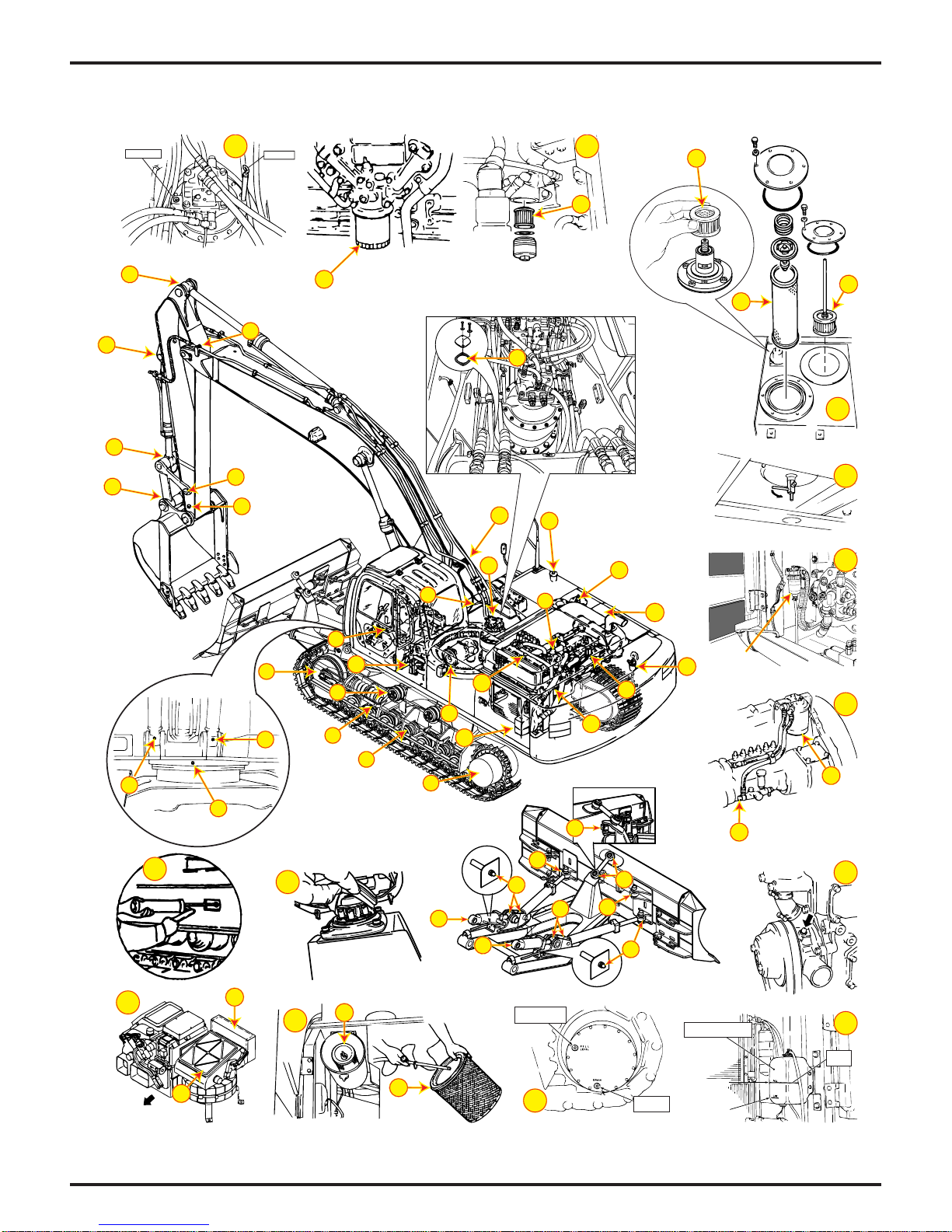
SK160LC/ED190-6E (Minor Change) COMPONENT FAMILIARIZATION
FILL PLUG
6
DIPSTICK
21
C
D
9
E
B
A
9
9
13
1
9
9
9
9
9
9
16
6
2
1
21
16
20
9
22
FRONT
11
8
Drain every 50 hrs
20
and clean every 500 hrs
19
11
22
3
14
17
19
12
18
5
9
4
7
H
10
9
I
9
PROPER
LEVEL
12
18
8
9
9
9
9
J
17
K
F
G
FILL/LEVEL
PLUG
7
9
9
9
RADIATOR EXPANSION
TANK
FULL
DRAIN
PLUG
LOW LEVEL
Page 3-6
Dynamic Acera 03/05 Rev. 05
SK160LC/ED190-6E (Minor Change) COMPONENT MAINTENANCE
E6-CL061KS E6-091DE
41Xcc061
41X)zO.lF14.5(
2XL7.4
)2XlaG42.1(
SEITICAPAC
)laG42(L19
L951
)laG0.24(
)laG4(L51
)laG4.3(L31
4X)zOdiulF96.1(cc05
41Xcc022
41X)zO.lF44.7(
2X)zOdiulF67.6(cc002
L5.7
)laG0.2(
2XL9
)2XlaG4.2(
tniojhcaenideriuqersA
secalP61
)rezoD(secalP41
)4Xº09(ecalP1
secalP2
gK7.8
)sbl2.91(
*
DIGIRF
C¡51~C¡03-
)F¡95~F¡22-(
22GVOSI
*
22-()evobadnaF¡68()F¡401~F¡32(
DIGIRF
C¡03~C¡02-
)F¡68~F¡4-(
23GVOSI
C¡03~C¡03-evobadnaC¡03C¡04~C¡5-
)F¡68~F¡
o
N.I.G.L.N
EPYTDIULF
REBMUNTRAP;TNACIRBUL
)gnimaof-nondnatnadixoitna,raew-itnA(LIOCILUARDYH
lio64SULLETLLEHShtiwyrotcafmorfdeppihserasenihcaM
MRAW-DIGIRF
C¡04~C¡52-
S23GVOSI
04W51EAS03W01EAS
*
MRAW
C¡04~C¡5-
)F¡401~F¡31-(
)F¡401~F¡32(
64GVOSI
*
)"DCecivreS"rofnoitacifisalc.I.P.A(LIOENIGNE
lio04W51EAShtiwyrotcafmorfdeppihserasenignellA
TOHYREV
C¡55~C¡5
)F¡131~F¡14(
86GVOSI
TOHYREVMRAWDIGIRF
05W51EAS
NOITCEPSNI
LAVRETNI
TSRIF
ECNANETNIAM
srH8 — srH0002
srH8srH05srH005
— — srH0002
— — srH0002
)"DCecivreS"rofnoitacifisalc.I.P.A(LIOENIGNE
lio04W51EAShtiwyrotcafmorfdeppihserastnenopmocesehT
— — srH0002
srH021 srH005 srH0002
srH021 srH005 srH0002
srH021——
ESAERG2PE
)esaergepytPE2.oNesoprupitlumerusserpemertxE(
srH05——
srH005——
srH05——
2…N.I.G.L.NASARG
)gniraebrofesabmuihtiL(
SOMhtiwesaergesabmuihtil2
2
srH005 — —
srH005— srH0002
.FER
)noitacoL(
knatciluardyH
1
TNENOPMOC
metsysciluardyH
naplioenignE
)level-H(
2
naplioenignE
)level-L(
3
4
5
6
7
8
9
01
11
21
31
srellorreppU
srellorrewoL
sreldI
tinunoitcudergniwS
tinunoitcuderlevarT
tniojrevelgnitarepO
sniptnemhcattA
gniraebgniwS
noisnetkcarT
tnemtsujda
gniraebpmupretaW )tohsnugesaergeno.xorpA(cc1.6
gnirgniwelS
htabesaerg
LAMRON
ECNANETNIAM
LAVRETNI
41
51
61
rotaidaR
metsysgnilooC
emulovlatot
knatleuF
A
B
C
D
E
F
G
H
I
J
K
)laG9.2(L11
L91
)laG5(
L182
)laG2.47(
retlifnrutermetsysciluardyH
)rekaerbhtiwdeppiuqesenihcamroF(retlifnruteR
reniartsnoitcusciluardyH
retlifevlavrehtaerbknatciluardyH
retlifmetsystoliP
retliflioenignE
tnemelerennirenaelcriA
tnemeleretuorenaelcriA
retlifleufenignE
retlifezuagpmupgnimirP
retlifriahserfC/A
retlifriaetalucricerC/A
erutxiM
retniW)¡31-~F¡5-(
o
N579DMTSALESEID
:tnemelE )1(1P40000V05RY :tiK 4F20000T03VY
:tnemelE )1(1P10000V05NY :tiK 4F20000T03VY
tbootsnoitcurtsni
)F…2.92-(C…43-)CLL(EZEERFITNA
.erutximreporpnia
LEUFLESEID
)F…32~F…5(dezi
o
N579DMTSALESEID1
lliwenihcamehterutarepmettsedlocehtnahtrewol)F…9(C…5ottcetorpdluohsoitar
rerutcafunamezeerfitnawolloF.srotcafllihcdniwnoitaredisnocotniekaT.ecneirepxe
TOHYREVMRAWDIGIRF
evobadna)F…32(C…5-C¡51-~C¡1-C¡52-~C¡51-
o
N579DMTSALESEID2
2
srH8 — srH0002
———
— srH05 srH005
—srH05srH005
)6D19Z54:N/PlaessedulcnI()1(100S20000V05NY
)1(010S20000V75NY
)1(500S10010V05NY
)1(200512EMAV*
)1(6S772R6442
)1(5S772R6442
)1()328610EMAV*(A2-421R1542
)1(156717EMAV*
)1(1P60010V05NY
)1(050S40000M02TY
srH8 deriuqersA
srH8deriuqersA
srH05srH005
srH05 srH005
srH0002
srH0002
srH005
srH005
srH052
srH005
srelaedocleboKtaylnoelbaliavA*
Dynamic Acera 03/05 Rev. 05
Page 3-7

MACHINE FAMILIARIZATION
SK210LC-VI -
The following performance specifications are based on the standard machine with standard attachment.
1. Travel Speed, Swing Speed & Gradeability
DESCRIPTION SPECIFICATION
TRAVEL SPEED 6.0 km per hr (3.7 mph) in mode.
SWING SPEED 11 RPM IN M-Mode / “HI” Idle.
GRADEABILITY 70% (35°) {Limited by engine lubrication}
DRAWBAR FORCE 20,190 Kgf (44,512 lbs)
2. Engine
Engine Maker Mitsubishi
Model 6D34-TEB
Type
Number of Cylinders– Bore X Stroke
4.53")
Displacement 5,861 liter (358 cu in.)
Compression Ratio 16.5 : 1
Output Rating 107 kW (144 HP) / 2,000 rpm
Maximum Torque 519 N•m (383 lb-ft)/ 1,600 rpm
Ignition Order 1–5–3–6–2–4 Clockwise Rotation
Injection Timing 15° Before Top Dead Point
Intake Valve Clearance Cold 0.4 mm (0.0157")
Exhaust Valve Clearance Cold 0.4 mm (0.0157")
Electrical System D.C. 24 V
Starting Motor 24 V–5.0 kW
Alternator 24 V–35 A
Batteries 2– 12 V- (136 Ah)
Engine Dry Weight* 470 kg (1,040 lbs)
Thermostat Begin to open at 76.5°C (170°F).
Cooling Fan Drive Method Ø600 (Ø24") Suction Type Belt
Air Cleaner Dry Type with Safety Elements
3. Hydraulic Components
COMPONENT TYPE
HYDRAULIC PUMPS Tandem, Variable Displacement,
2X210 L/min (55.5 Gal/min)
SWING MOTOR Axial Piston
TRAVEL MOTOR Axial Piston
CONTROL VALVES 6 Spool Multiple Control
CYLINDERS (ALL) Double Acting
RETURN FILTER Safety Valve containing Filter Type
OIL COOLER Air Cooled
PERFORMANCE SPECIFICA TIONS
4.0 km per hr (2.5 mph) in mode.
4-Cycle, Water Cooled, Direct
Injection with Turbocharger , Diesel
6–104 mm X 115 mm (4.09" X
Full open at 90°C (194°F).
Drive Pulley Ratio : 1.00
*Less flywheel and electrics.
Axial Piston with Pilot Gear Pump.
1A. MACHINE & COMPONENT WEIGHTS
The following weight specifications are based on
the standard machine with standard attachment.
Unit: Kg (lb)
COMPONENT SK210LC-VI
COMPLETE MACHINE (STANDARD) 20,500 (45,200)
UPPER FRAME ASSEMBL Y
COUNTERWEIGHT 4,500 (9,920)
CAB 260 (570)
BOOM CYLINDER* 168 (370) X 2
ENGINE* 470 (1,040)
RADIA TOR & OIL COOLER 97 (210)
PUMP ASSEMBLY 142 (310)
CONTROL VALVE 280 (620)
FUEL T ANK* 91 (200)
HYDRAULIC TANK* 143 (320)
SWING MOTOR & REDUCTION UNIT
LOWER FRAME ASSEMBL Y
SLEWING RING 245 (540)
TRA VEL MOTOR & REDUCTION UNIT
IDLER ASSEMBL Y 106 (230) X2
LOWER ROLLER ASSEMBL Y 35 (77) X16
UPPER ROLLER ASSEMBL Y 22 (48) X4
TRACK TENSION ASSEMBLY 104 (230) X2
SPROCKET 54 (120) X2
SWIVEL JOINT 30 (66)
TRACK LINK W/ 800mm (31.5") SHOES
TRACK LINK 540 (1,190) X2
ATT ACHMENT (STANDARD) 3,600 (7,930)
BUCKET ASSEMBL Y [0.81m3 (1.06 cu yd)]
ARM ASSEMBLY [2.94 m (9’-8”)] 980 (2,160)
ARM [2.94 m (9’-8”)] 610 (1,340)
BUCKET CYLINDER* 135 (300)
IDLER LINK 21 (46) X2
BUCKET LINK 91 (200)
PIN (2 PCS for mtg bucket cyl & bucket)
BOOM ASSEMBL Y 1,650 (3,640)
BOOM 1,320 (2,910)
ARM CYLINDER* 230 (510)
PIN (Mounting the Arm) 27 (59)
FLUIDS 540 (1,190)
HYD OIL 215 (470)
ENG OIL 20 (44)
FUEL 285 (630)
WATER 20 (44)
9,400 (20,720)
235 (520)
7,500 (16,530)
250 (550) X2
1,720 (3,784) X2
650 (1,430)
65 (140)
* DRY WEIGHT
4. Operating Pressures
PILOT SYSTEM 50 (710)
IMPLEMENT 350 (4980)
SWING 285 (4050)
TRAVEL 350 (4980)
POWER BOOST/HEAVY LIFT 385 (5470)
Page 3-8
Kgf/cm2 (psi)
W ARNING
USE ONL Y LIFTING DEVICES AND EQUIPMENT WITH
RA TED CAP ACITIES SUFFICIENT TO LIFT THE SPECIFIC COMPONENT(S) BEING REMOVED OR INST ALLED.
Dynamic Acera 03/05 Rev. 05

MACHINE F AMILIARIZATION
SK250LC-VI -
The following performance specifications are based on the standard machine with standard attachment.
1. Travel Speed, Swing Speed & Gradeability
DESCRIPTION SPECIFICATION
TRAVEL SPEED 6.0 km per hr (3.7 mph) in mode.
SWING SPEED 11 RPM IN M-Mode / “HI” Idle.
GRADEABILITY 70% (35°) {Limited by engine lubrication}
DRAWBAR FORCE 20,190 Kgf (44,512 lbs)
2. Engine
Engine Maker Mitsubishi
Model 6D34-TLEB
Type
Number of Cylinders– Bore X Stroke
Displacement 5,861 liter (358 cu in.)
Compression Ratio 18.2 : 1
Output Rating 125 kW (168 HP) / 2,100 rpm
Maximum Torque 590 N•m (435 lb-ft)/ 1,600 rpm
Ignition Order 1–5–3–6–2–4 Clockwise Rotation
Injection Timing 17° Before Top Dead Point
Intake Valve Clearance Cold 0.4 mm (0.0157")
Exhaust Valve Clearance Cold 0.4 mm (0.0157")
Electrical System D.C. 24 V
Starting Motor 24 V–5.0 kW
Alternator 24 V–35 A
Batteries 2– 12 V- (136 Ah)
Engine Dry Weight* 470 kg (1,040 lbs)
Thermostat Begin to open at 76.5°C (170°F).
Cooling Fan Drive Method Ø600 (Ø24") Suction Type Belt
Air Cleaner Dry Type with Safety Elements
3. Hydraulic Components
COMPONENT TYPE
HYDRAULIC PUMPS Tandem, Variable Displacement,
2X240 L/min (63.4 Gal/min)
SWING MOTOR Axial Piston
TRAVEL MOTOR Axial Piston
CONTROL VALVES 6 Spool Multiple Control
CYLINDERS (ALL) Double Acting
RETURN FILTER Safety Valve containing Filter Type
OIL COOLER Air Cooled
PERFORMANCE SPECIFICA TIONS
4.0 km per hr (2.5 mph) in mode.
4-Cycle, Water Cooled, Direct
Injection with Turbocharger , Diesel
6–104 mm X 1 15 mm (4.09" X 4.53")
Full open at 90°C (194°F).
Drive Pulley Ratio : 1.00
*Less flywheel and electrics.
Axial Piston with Pilot Gear Pump.
1A. MACHINE & COMPONENT WEIGHTS
The following weight specifications are based on
the standard machine with standard attachment.
Unit: Kg (lb)
COMPONENT SK250LC-VI
COMPLETE MACHINE (STANDARD) 24,100 (53,130)
UPPER FRAME ASSEMBL Y
COUNTERWEIGHT 5,510 (12,150)
CAB 260 (570)
BOOM CYLINDER* 220 (490) X 2
ENGINE* 480 (1,060)
RADIAT OR & OIL COOLER 97 (210)
PUMP ASSEMBLY 142 (310)
CONTROL VALVE 280 (620)
FUEL TANK* 91 (200)
HYDRAULIC TANK* 143 (320)
SWING MOTOR & REDUCTION UNIT
LOWER FRAME ASSEMBL Y
SLEWING RING 364 (800)
TRAVEL MOTOR & REDUCTION UNIT
IDLER ASSEMBL Y 106 (230) X2
LOWER ROLLER ASSEMBL Y 35 (77) X16
UPPER ROLLER ASSEMBL Y 22 (48) X4
TRACK TENSION ASSEMBLY 94 (210) X2
SPROCKET 54 (120) X2
SWIVEL JOINT 30 (66)
TRACK LINK W/ 800mm (31.5") SHOES
TRACK LINK 580 (1,276) X2
ATT ACHMENT (STANDARD) 3,900 (8,600)
BUCKET ASSEMBL Y [0.81m3 (1.06 cu yd)]
ARM ASSEMBLY [2.94 m (9’-8”)] 1,150 (2,540)
ARM [2.94 m (9’-8”)] 710 (1,570)
BUCKET CYLINDER* 177 (390)
IDLER LINK 25 (55) X2
BUCKET LINK 98 (220)
PIN (2 PCS for mtg bucket cyl & bucket)
BOOM ASSEMBL Y 2.140 (4,720)
BOOM 1,670 (3,680)
ARM CYLINDER* 300 (660)
PIN (Mounting the Arm) 28 (62)
FLUIDS 550 (1,210)
HYD OIL 225 (500)
ENG OIL 20 (44)
FUEL 285 (630)
WATER 22 (48)
11,400 (25,130)
290 (640)
8,800 (19,400)
300 (660) X2
1,490 (3,280) X2
780 (1,720)
80 (180)
* DRY WEIGHT
4. Operating Pressures
PILOT SYSTEM 50 (710)
IMPLEMENT 350 (4980)
SWING 285 (4050)
TRAVEL 350 (4980)
POWER BOOST/HEAVY LIFT 385 (5470)
Dynamic Acera 03/05 Rev. 05
Kgf/cm2 (psi)
W ARNING
USE ONL Y LIFTING DEVICES AND EQUIPMENT WITH
RA TED CAP ACITIES SUFFICIENT TO LIFT THE SPECIFIC COMPONENT(S) BEING REMOVED OR INST ALLED.
Page 3-9
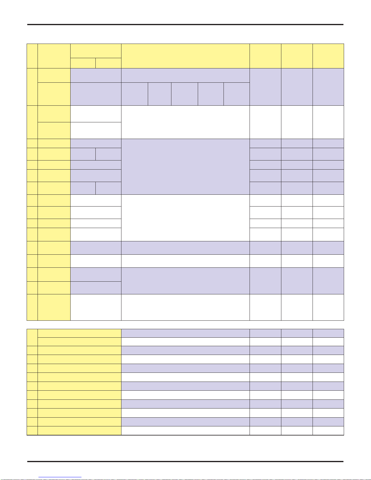
SK210LC/SK250-6E (Minor Change) COMPONENT FAMILIARIZATION
SK210/SK250LC-6E-MC
FILL PLUG
9
9
9
6
DIPSTICK
21
C
D
E
B
A
9
9
13
9
9
1
16
10
9
20
9
9
16
8
22
FRONT
11
6
9
2
8
5
22
3
14
17
11
18
4
12
1
Drain every 50 hrs
and clean every 500 hrs
21
19
20
19
H
I
12
7
J
17
K
F
G
Use low pressure air
for cleaning
FILL/LEVEL
PLUG
7
DRAIN
PLUG
RADIATOR EXPANSION
TANK
FULL
LOW LEVEL
PROPER
LEVEL
18
Page 3-10
Dynamic Acera 03/05 Rev. 05
SK210LC/SK250-6E (Minor Change) COMPONENT MAINTENANCE
SK210/SK250LC-6E-MC
gK3.8
)laG56(
)laG0.2(
2XL5.5
)sbl3.81(
E6-CL012KS E6-CL052KS
)2XlaG5.1(
SEITICAPAC
*
L062
)laG96(
)laG8.4(L81
)laG1.4(L5.51
41X).zOdiulF14.5(cc061
CL-61X).zOdiulF14.5(cc061
L3.51
)laG0.4(
2XL7.4
)2XlaG2.1(
DIGIRF
C¡51~C¡03-
22GVOSI
DIGIRF
)F¡95~F¡22-(
C¡03~C¡02-
)F¡68~F¡4-(
23GVOSI
*
C¡03~C¡03-evobadnaC¡03C¡04~C¡5-
)F¡68~F¡
22-()evobadnaF¡68()F¡401~F¡32(
EPYTDIULF
REBMUNTRAP;TNACIRBUL
)gnimaof-nondnatnadixoitna,raew-itnA(LIOCILUARDYH
lio64SULLETLLEHShtiwyrotcafmorfdeppihserasenihcaM
MRAW-DIGIRF
C¡04~C¡52-
)F¡401~F¡31-(
S23GVOSI
04W51EAS03W01EAS
*
MRAW
C¡04~C¡5-
)F¡401~F¡32(
64GVOSI
*
)"DCecivreS"rofnoitacifisalc.I.P.A(LIOENIGNE
lio04W51EAShtiwyrotcafmorfdeppihserasenignellA
)"DCecivreS"rofnoitacifisalc.I.P.A(LIOENIGNE
TOHYREV
C¡55~C¡5
)F¡131~F¡14(
86GVOSI
TOHYREVMRAWDIGIRF
05W51EAS
lio04W51EAShtiwyrotcafmorfdeppihserastnenopmocesehT
NOITCEPSNI
LAVRETNI
TSRIF
ECNANETNIAM
srH8 srH0002
srH8srH05srH005
srH021 srH005 srH0002
srH021 srH005 srH0002
srH021
ESAERG2PE
secalp2
2…N.I.G.L.NASARG
)gniraebrofesabmuihtiL(
gK3.11
)sbl9.42(
o
N.I.G.L.N
)esaergepytPE2.oNesoprupitlumerusserpemertxE(
SOMhtiwesaergesabmuihtil2
2
srH05
srH005
srH05
srH005
srH005srH0002
.FER
)noitacoL(
knatciluardyH )laG14(L651
1
TNENOPMOC
metsysciluardyH
*naplioenignE
)level-H(
L642
2
*naplioenignE
)level-L(
3
4
5
6
7
8
9
01
11
21
31
srellorreppU 4X).zOdiulF96.1(cc05
srellorrewoL
sreldI 2X).zOdiulF67.6(cc002
tinunoitcudergniwS
tinunoitcuderlevarT
tniojrevelgnitarepO tniojhcaenideriuqersA
sniptnemhcattA secalP61
gniraebgniwS )4X…09(ecalP1
noisnetkcarT
tnemtsujda
gniraebpmupretaW )tohsnugesaergeno.xorpA(cc1.6
gnirgniwelS
htabesaerg
L5.7
LAMRON
ECNANETNIAM
LAVRETNI
srH0002
srH0002
srH0002
41
51
61
* )laG3.6(L42:emulovlioenignelatoT;laudiser)laG3.1(L9.4;)laG3.0(L1.1:yticapacretliF
A
B
C
D
E
F
G
H
I
J
K
rotaidaR )laG5.2(L5.9
metsysgnilooC
emulovlatot
knatleuF
erutxiM
L91
)laG5(
retlifmetsystoliP )500S10010V05NY:N/Plaesgnir-OsedulcnI()1(500S10010V05NY
retliflioenignE )1(200512EMAV*
retlifleufenignE )1(452510EMAV*
retlifriahserfC/A )1(1P60010V05NY
L22
)laG8.5(
L043
)laG09(
retlifnrutermetsysciluardyH :tnemelE )1(1P10000V05RY :tiK 1F70000T03NY
)rekaerbhtiwdeppiuqesenihcamroF(retlifnruteR :tnemelE )1(1P90000V05NY :tiK 2F70000T03NY
reniartsnoitcusciluardyH )6D19Z54:N/PlaessedulcnI()1(100S20000V05NY
retlifevlavrehtaerbknatciluardyH )1(010S20000V75NY
tnemelerennirenaelcriA )1(6S552R6442
tnemeleretuorenaelcriA )1(5S552R6442
retlifezuagpmupgnimirP )1(156717EMAV*
retlifriaetalucricerC/A )1(050S40000M02TY
tniW)¡31-~F¡5-(
o
N579DMTSALESEID
tbootsnoitcurtsni
)F…2.92-(C…43-)CLL(EZEERFITNA
.erutximreporpnia
LEUFLESEID
)F…32~F…5(dezire
o
N579DMTSALESEID1
lliwenihcamehterutarepmettsedlocehtnahtrewol)F…9(C…5ottcetorpdluohsoitar
rerutcafunamezeerfitnawolloF.srotcafllihcdniwnoitaredisnocotniekaT.ecneirepxe
TOHYREVMRAWDIGIRF
evobadna)F…32(C…5-C¡51-~C¡1-C¡52-~C¡51-
o
N579DMTSALESEID2
2
srH8 srH0002
srH005
srH05 srH005
srH05srH005
srH0002
srH0002
srH005
srH05srH005
srH8 deriuqersA
srH8deriuqersA
srH05 srH005
srH005
srH052
srH005
srelaedOCLEBOKtaylnoelbaliavA*
Dynamic Acera 03/05 Rev. 05
Page 3-11
MACHINE F AMILIARIZATION
SK290LC-VI -
The following performance specifications are based on the standard machine with standard attachment.
1. Travel Speed, Swing Speed & Gradeability
DESCRIPTION SPECIFICATION
TRAVEL SPEED 5.6 km per hr (3.5 mph) in mode.
SWING SPEED 11 RPM IN M-Mode / “HI” Idle.
GRADEABILITY 70% (35°) {Limited by engine lubrication}
DRAWBAR FORCE 26,218 Kgf (57,800 lbs)
2. Engine
Engine Maker Mitsubishi
Model 6D16-TLEC
Type
Number of Cylinders– Bore X Stroke
Displacement 7,545 liter (460 cu in.)
Compression Ratio 17.5 : 1
Output Rating 138 kW (185 HP) / 2,100 rpm
Maximum Torque 726 N•m (534 lb-ft)/ 1,600 rpm
Ignition Order 1–5–3–6–2–4 Clockwise Rotation
Injection Timing 15° Before Top Dead Point
Intake Valve Clearance Cold 0.4 mm (0.0157")
Exhaust Valve Clearance Cold 0.4 mm (0.0157")
Electrical System D.C. 24 V
Starting Motor 24 V–5.0 kW
Alternator 24 V–35 A
Batteries 2– 12 V- (136 Ah)
Engine Dry Weight* 580 kg (1,280 lbs)
Thermostat Begin to open at 76.5°C (170°F).
Cooling Fan Drive Method Ø620 (Ø24.2") Suction Type Belt
Air Cleaner Dry Type with Safety Elements
3. Hydraulic Components
COMPONENT TYPE
HYDRAULIC PUMPS Tandem, Variable Displacement,
2X210 L/min (55.5 Gal/min)
SWING MOTOR Axial Piston
TRAVEL MOTOR Axial Piston
CONTROL VALVES 6 Spool Multiple Control
CYLINDERS (ALL) Double Acting
RETURN FILTER Safety Valve containing Filter Type
OIL COOLER Air Cooled
4. Operating Pressures
PILOT SYSTEM 50 (710)
IMPLEMENT 350 (4980)
SWING 280 (3980)
TRAVEL 350 (4980)
POWER BOOST/HEAVY LIFT 385 (5470)
PERFORMANCE SPECIFICA TIONS
3.5 km per hr (2.2 mph) in mode.
4-Cycle, Water Cooled, Direct
Injection with Turbo & Inner cooler
6–118 mm X 115 mm (4.65" X 4.53")
Full open at 90°C (194°F).
Drive Pulley Ratio : 0.90
*Less flywheel and electrics.
Axial Piston with Pilot Gear Pump.
Kgf/cm2 (psi)
1A. MACHINE & COMPONENT WEIGHTS
The following weight specifications are based on the
standard machine with standard attachment.
COMPONENT SK290LC-VI
COMPLETE MACHINE (STANDARD) 30,000 (66,100)
UPPER FRAME ASSEMBL Y
COUNTERWEIGHT 6,118 (13,484)
CAB + CONTROLS + A/C + SEAT 836 (1,843)
BOOM CYLINDER* 270 (595) X 2
ENGINE + MUFFLER + MINOR ITEMS 716 (1,578)
RADIAT OR & OIL COOLER 175 (386)
PUMP ASSEMBLY + COUPLING 148 (326)
CONTROL VALVE 441 (972)
FUEL TANK* 170 (375)
HYDRAULIC TANK* 173 (381)
SWING MOTOR & REDUCTION UNIT 511 (1,126)
UPPER FRAME + GUARDS & COVERS 3,109 (6,852)
LOWER FRAME ASSEMBL Y 11,232 (24,755)
CAR BODY 3,618 (7,974)
SLEWING RING 586 (1,292)
TRAVEL MOTOR + RED. UNIT 309 (697) X2
IDLER ASSEMBL Y 170 (370) X2
LOWER ROLLER ASSEMBL Y 45 (77) X18
UPPER ROLLER ASSEMBL Y 26 (57) X4
TRACK TENSION ASSEMBLY 127 (280) X2
SPROCKET + BOLTS 76 (168) X2
SWIVEL JOINT + LOWER LINES 74 (163)
TRACK CHAINS W/800mm (31.5”) SHOES
TRACK GUIDES + GREASE BATH + MOT OR COVERS
ATT ACHMENT (ST ANDARD) 5,136 (1 1,320)
BUCKET ASSEMBL Y [1.20M3 (1.57 CU YD)] 954 (2,100)
ARM ASSEMBLY [3.2 m (10’- 6”) 1,485 (3,273)
ARM 952 (2,098)
BUCKET CYLINDER 220 (485)
IDLER LINK 27 (60) X2
BUCKET LINK 130 (290)
PIN
(6 PCS for mtg bucket cyl, links, bckt &arm cyl rod)
BOOM ASSEMBL Y 2,697 (5,944)
BOOM 2,116 (4,664)
ARM CYLINDER* 370 (816)
PINS
(4 PCS for mtg arm cyl, boom cyl’s & boom)
FLUIDS 554 (1,221)
HYD OIL 171 (377)
FUEL 348 (767)
WATER 35 (77)
Unit: Kg (lb)
12,937 (28,513)
2,338 (5,153) X2
90 (198)
139 (306)
211 (465)
* DRY WEIGHT
WARNING
USE ONLY LIFTING DEVICES AND EQUIPMENT
WITH RATED CAPACITIES SUFFICIENT TO LIFT
THE SPECIFIC COMPONENT(S) BEING REMOVED
OR INST ALLED.
Page 3-12
Dynamic Acera 03/05 Rev. 05
MACHINE F AMILIARIZATION
SK330LC-VI -
The following performance specifications are based on the standard machine with standard attachment.
1. Travel Speed, Swing Speed & Gradeability
DESCRIPTION SPECIFICATION
TRAVEL SPEED 5.8 km per hr (3.6 mph) in mode.
SWING SPEED 11 RPM IN M-Mode / “HI” Idle.
GRADEABILITY 70% (35°) {Limited by engine lubrication}
DRAWBAR FORCE 28,950 Kgf (63,800 lbf)
2. Engine
Engine Maker Mitsubishi
Model 6D16-TLEB
Type
Number of Cylinders– Bore X Stroke
Displacement 7,545 liter (460 cu in.)
Compression Ratio 17.5 : 1
Output Rating 177 kW (238 Hp) / 2,200 rpm
Maximum Torque 824 N•m (608 lb-ft)/ 1,800 rpm
Ignition Order 1–5–3–6–2–4 Clockwise Rotation
Injection Timing 14° Before Top Dead Point
Intake Valve Clearance Cold 0.4 mm (0.0157")
Exhaust Valve Clearance Cold 0.4 mm (0.0157")
Electrical System D.C. 24 V
Starting Motor 24 V–5.0 KW
Alternator 24 V–35 A
Batteries 2– 12 V- (136 Ah)
Engine Dry Weight* 580 kg (1,280 lbs)
Thermostat Begin to open at 76.5°C (170°F).
Cooling Fan Drive Method Ø620 (Ø24.2") Suction Type Belt
Air Cleaner Dry Type with Safety Elements
3. Hydraulic Components
COMPONENT TYPE
HYDRAULIC PUMPS Tandem, Variable Displacement,
2X242 L/min (63.4 Gal/min)
SWING MOTOR Axial Piston
TRAVEL MOTOR Axial Piston
CONTROL VALVES 6 Spool Multiple Control
CYLINDERS (ALL) Double Acting
RETURN FILTER Safety Valve containing Filter Type
OIL COOLER Air Cooled
4. Operating Pressures
PILOT SYSTEM 50 (710)
IMPLEMENT 350 (4980)
SWING 280 (3980)
TRAVEL 350 (4980)
POWER BOOST/HEAVY LIFT 385 (5470)
PERFORMANCE SPECIFICA TIONS
3.4 km per hr (2.1 mph) in mode.
4-Cycle, Water Cooled, Direct
Injection with Turbo & Innercooler
6–118 mm X 115 mm (4.65" X 4.53")
Full open at 90°C (194°F).
Drive Pulley Ratio : 0.90
*Less flywheel and electrics.
Axial Piston with Pilot Gear Pump.
Kgf/cm2 (psi)
1A. MACHINE & COMPONENT WEIGHTS
The following weight specifications are based on the
standard machine with standard attachment.
Unit: Kg (lb)
COMPONENT SK330LC-VI
COMPLETE MACHINE (STANDARD) 35,300 (77,800)
UPPER FRAME ASSEMBL Y
COUNTERWEIGHT 8,420 (18,558)
CAB + CONTROLS + A/C + SEAT 836 (1,843)
BOOM CYLINDER* 270 (595) X 2
ENGINE + MUFFLER + MINOR ITEMS 716 (1,578)
RADIAT OR & OIL COOLER 175 (386)
PUMP ASSEMBLY + COUPLING 148 (326)
CONTROL VALVE 475 (1,047)
FUEL TANK* 204 (450)
HYDRAULIC TANK* 173 (381)
SWING MOTOR & REDUCTION UNIT 511 (1,126)
UPPER FRAME + GUARDS & COVERS 3,800 (8,375)
LOWER FRAME ASSEMBL Y 12,362 (27,167)
CARBODY 3,990 (8,794)
SLEWING RING 586 (1,292)
TRAVEL MOTOR + RED. UNIT 360 (790) X2
IDLER ASSEMBL Y 170 (370) X2
LOWER ROLLER ASSEMBL Y 58 (130) X18
UPPER ROLLER ASSEMBL Y 30 (66) X4
TRACK TENSION ASSEMBLY 190 (420) X2
SPROCKET + BOLTS 88 (190) X2
SWIVEL JOINT + LOWER LINES 85 (187)
TRACK CHAINS W/800mm (31.5”) SHOES
TRACK GUIDES + GREASE NBA TH + MOTOR COVERS
ATT ACHMENT (STANDARD) 6,134 (13,519)
BUCKET ASSEMBL Y [1.20M3 (1.57 CU YD)] 1,040 (2,290)
ARM ASSEMBLY [3.2 m (10’- 6”) 1,785 (3,875)
ARM 1,160 (2,560)
BUCKET CYLINDER 260 (570)
IDLER LINK 27 (60) X2
BUCKET LINK 130 (290)
PIN
(6 PCS for mtg bucket cyl, links, bckt &arm cyl rod)
BOOM ASSEMBL Y 3,336 (7,353)
BOOM 2,580 (5,690)
ARM CYLINDER* 500 (1,100)
PINS
(4 PCS for mtg arm cyl, boom cyl’s & boom)
FLUIDS 805 (1,774)
HYD OIL 304 (670)
FUEL 466 (1,030)
WATER 35 (77)
15,998 (35,260)
2,390 (5,286) X2
105 (231)
139 (306)
256 (485)
* DRY WEIGHT
WARNING
USE ONLY LIFTING DEVICES AND EQUIPMENT
WITH RATED CAPACITIES SUFFICIENT TO LIFT
THE SPECIFIC COMPONENT(S) BEING REMOVED
OR INST ALLED.
Dynamic Acera 03/05 Rev. 05
Page 3-13
SK290LC/SK330-6E (Minor Change) COMPONENT FAMILIARIZATION
FILL PLUG
9
9
9
6
DIPSTICK
OIL
FILTER
21
D
B
C
A
E
13
1
9
9
B101GreaseBathCover
9
9
16
20
10
Drain every 50 hrs
9
9
9
16
and clean every 500 hrs
19
8
22
FRONT
11
6
9
2
8
5
22
3
14
17
11
18
1
H
21
I
20
19
12
12
4
7
J
17
K
F
G
Use low pressure air
FILL/LEVEL
PLUG
7
DRAIN
PLUG
RADIATOR EXPANSION
TANK
FULL
LOW LEVEL
PROPER
LEVEL
18
Page 3-14
Dynamic Acera 03/05 Rev. 05
SK290LC/SK330-6E (Minor Change) COMPONENT MAINTENANCE
E6-CL092KS E6-CL033KS
secalp2
gK7.51
)sbl6.43(
SEITICAPAC
*
DIGIRF
C¡51~C¡03-
22GVOSI
)laG4.7(L82*
)laG1.6(L32*
DIGIRF
)F¡95~F¡22-(
C¡03~C¡02-
)F¡68~F¡4-(
23GVOSI
*
C¡03~C¡03-evobadnaC¡03C¡04~C¡5-
22-()evobadnaF¡68()F¡401~F¡32(
)F¡68~F¡
EPYTDIULF
REBMUNTRAP;TNACIRBUL
)gnimaof-nondnatnadixoitna,raew-itnA(LIOCILUARDYH
lio64SULLETLLEHShtiwyrotcafmorfdeppihserasenihcaM
MRAW-DIGIRF
C¡04~C¡52-
S23GVOSI
04W51EAS03W01EAS
*
MRAW
C¡04~C¡5-
)F¡401~F¡31-(
)F¡401~F¡32(
*
64GVOSI
)"DCecivreS"rofnoitacifisalc.I.P.A(LIOENIGNE
lio04W51EAShtiwyrotcafmorfdeppihserasenignellA
)"DCecivreS"rofnoitacifisalc.I.P.A(LIOENIGNE
)noitacifisalc.I.P.Ayb4-LGedarG(LIORAEG
09#lioraegerusserpemertxE
TOHYREV
C¡55~C¡5
)F¡131~F¡14(
86GVOSI
TOHYREVMRAWDIGIRF
05W51EAS
lio04W51EAShtiwyrotcafmorfdeppihserastnenopmocesehT
NOITCEPSNI
LAVRETNI
TSRIF
ECNANETNIAM
srH8 srH0002
srH8srH05srH005
srH021 srH005 srH0002
srH021 srH005 srH0002
srH021
ESAERG2PE
)esaergepytPE2.oNesoprupitlumerusserpemertxE(
srH05
srH005
srH05
2…N.I.G.L.NASARG
)gniraebrofesabmuihtiL(
o
N.I.G.L.N
SOMhtiwesaergesabmuihtil2
2
srH005
srH005srH0002
TNENOPMOC
.FER
)noitacoL(
knatciluardyH )laG5.25(L791 )laG45(L602
1
metsysciluardyH )laG0.39(L153
*naplioenignE
)level-H(
2
*naplioenignE
)level-L(
3
4
5
6
7
8
9
01
11
21
31
srellorreppU 4X)zO.lF96.1(cc05 4X)zO.lF4.3(cc001
srellorrewoL 81X)zO.lF1.01(cc003 61X)zO.lF1.41(cc034
sreldI 2X)zO.lF5.8(cc052 2X)zO.lF1.11(cc053
tinunoitcudergniwS )laG7.5(L5.12
tinunoitcuderlevarT 2X)laG8.2(L5.01
tniojrevelgnitarepO deriuqersA
sniptnemhcattA secalP61
gniraebgniwS )4X…09(ecalP1
noisnetkcarT
tnemtsujda
gniraebpmupretaW )tohsnugesaergeno.xorpA(cc1.6
gnirgniwelS
htabesaerg
LAMRON
ECNANETNIAM
LAVRETNI
srH0002
srH0002
srH0002
41
51
61
*
A
B
C
D
E
F
G
H
I
J
K
rotaidaR )laG4(L51
metsysgnilooC
emulovlatot
knatleuF
L024
)laG211(
)laG5.8(L23:)retlifgnidulcni(emulovlioenignelatoT
erutxiM
)laG9(L43
L065
)laG841(
retlifnrutermetsysciluardyH :tiktnemelE )1(3F40000V05NY
)rekaerbhtiwdeppiuqesenihcamroF(retlifnruteR :tnemelE )1(1P90000V05NY :laeS 00002G11DZ
reniartsnoitcusciluardyH )6D19Z54:N/PlaessedulcnI()1(1F10000V05CL
retlifevlavrehtaerbknatciluardyH )1(010S20000V75NY
retlifmetsystoliP )1(500S10010V05NY
retliflioenignE )1(869031EMAV*
tnemelerennirenaelcriA )1(1P31010P11NY
tnemeleretuorenaelcriA )1(200S10000P11NY
retlifleufenignE )1(076550EMAV*
retlifezuagpmupgnimirP )1(956717EMAV*
retlifriahserfC/A )1(1P60010V05NY
retlifriaetalucricerC/A )1(050S40000M02TY
o
N579DMTSALESEID
tbootsnoitcurtsni
)F…2.92-(C…43-)CLL(EZEERFITNA
.erutximreporpnia
LEUFLESEID
32~F…5(deziretniW)¡31-~F¡5-(
)F…
o
N579DMTSALESEID1
lliwenihcamehterutarepmettsedlocehtnahtrewol)F…9(C…5ottcetorpdluohsoitar
rerutcafunamezeerfitnawolloF.srotcafllihcdniwnoitaredisnocotniekaT.ecneirepxe
TOHYREVMRAWDIGIRF
evobadna)F…32(C…5-C¡51-~C¡1-C¡52-~C¡51-
o
N579DMTSALESEID2
2
srH8 srH0002
srH05 srH005
srH05srH005
srH0002
srH0002
srH005
srH05srH005
srH8 deriuqersA
srH8deriuqerrA
srH05 srH005
srH005
srH052
srH005
srelaedOCLEBOKtaylnoelbaliavA*
Dynamic Acera 03/05 Rev. 05
Page 3-15

MACHINE F AMILIARIZATION
SK480 -
DESCRIPTION SPECIFICATION
TRA VEL SPEED 5.6 km per hr (3.5 mph) in mode.
SWING SPEED 9 RPM IN M-Mode / “HI” Idle.
GRADEABILITY 70% (35°) {Limited by engine lubrication}
DRAWBAR FORCE 26,218 Kgf (57,800 lbs)
Engine Maker Mitsubishi
Model 6D24-TLA2B
Type
Number of Cylinders– Bore X Stroke
Displacement 11.950 Liter (729 cu in.)
Compression Ratio 17.5 : 1
Output Rating 250kW (335 HP) / 2,130 rpm
Maximum Torque 1,275 N•m (940 lb-ft)/ 1,600 rpm
Ignition Order 1–5–3–6–2–4 Clockwise Rotation
Injection Timing 2° Before Top Dead Point
Intake Valve Clearance Cold 0.4 mm (0.0157")
Exhaust Valve Clearance Cold 0.6 mm (0.0236")
Electrical System D.C. 24 V
Starting Motor 24 V–5.0 KW
Alternator 24 V–35 A
Batteries 2– 12 V- (136 Ah)
Engine Dry Weight* 580 kg (1,280 lbs)
Thermostat Begin to open at 76.5°C (170°F).
Cooling Fan Drive Method Ø620 (Ø24.2") Suction Type Belt
Air Cleaner Dry Type with Safety Elements
COMPONENT TYPE
HYDRAULIC PUMPS Tandem, Variable Displacement,
2X210 L/min (55.5 Gal/min)
SWING MOTOR Axial Piston
TRAVEL MOTOR Axial Piston
CONTROL VALVES 6 Spool Multiple Control
CYLINDERS (ALL) Double Acting
RETURN FILTER Safety Valve containing Filter Type
OIL COOLER Air Cooled
PILOT SYSTEM 49.9 / (710) / [4.9 MPa]
IMPLEMENT 320 / (4554) / [31.4 MPa]
SWING 260 / (3698) / [25.5 MPa]
TRAVEL 349 / (4974) / [34.3 MPa]
POWER BOOST/HEAVY LIFT 349 / (4974) / [34.3 MPa]
PERFORMANCE SPECIFICA TIONS
The following performance specifications are based on the standard machine with standard attachment.
1. Travel Speed, Swing Speed & Gradeability
3.5 km per hr (2.2 mph) in mode.
2. Engine
4-Cycle, Water Cooled, Direct
Injection with Turb & Inner cooler
6–130 mm X 150 mm (5.12" X 5.91”)
Full open at 90°C (194°F).
Drive Pulley Ratio : 0.90
*Less flywheel and electrics.
3. Hydraulic Components
Axial Piston with Pilot Gear Pump.
4. Operating Pressures
Kgf/cm2 / (psi) / [ MPa]
1A. MACHINE & COMPONENT WEIGHTS
The following weight specifications are based on the
standard machine with standard attachment.
COMPONENT SK480LC-VI
COMPLETE MACHINE (STANDARD) 49,100 (108,000)
UPPER FRAME ASSEMBL Y
COUNTERWEIGHT 10,027 (22,059)
CAB 260 (570)
BOOM CYLINDER* 422 (928) X 2
ENGINE + MUFFLER + MINOR ITEMS 1,100 (2,420)
RADIA TOR & OIL COOLER 186 (410)
PUMP ASSEMBLY 187 (420)
CONTROL VALVE 380 (840)
FUEL T ANK* 230 (510)
HYDRAULIC TANK* 360 (790)
SWING MOTOR & REDUCTION UNIT 722 (1,590)
LOWER FRAME ASSEMBL Y 19,000 (41,800)
SLEWING RING 700 (1,540)
TRAVEL MOTOR + RED. UNIT 650 (1,430) X2
IDLER ASSEMBL Y 270 (600) X2
LOWER ROLLER ASSEMBL Y 98 (220) X18
UPPER ROLLER ASSEMBL Y 30 (66) X4
TRACK TENSION ASSEMBL Y 325 (720) X2
SPROCKET + BOLTS 100 (220) X2
SWIVEL JOINT 58 (130)
TRACK GUIDE 50 (110) X 4
TRACK CHAINS W/900mm (35.4”) SHOES
TRACK LINK
ATT ACHMENT (STANDARD) 8,100 (17,860)
BUCKET ASSEMBL Y [1.80M3 (2.35 CU YD)] 1,440 (3,170)
ARM ASSEMBLY [3.45m (11’- 4”) 2,380 (5,250)
ARM [3.45 11’ - 4”] 1,450 (3,200)
BUCKET CYLINDER* 360 (790)
IDLER LINK 56 (120) X2
BUCKET LINK 150 (330)
PIN
(2 PCS for mtg bucket cyl, & bucket
BOOM ASSEMBL Y 4,240 (9,350)
BOOM 3,330 (7,280)
ARM CYLINDER* 590 (1,300)
PINS
(mounting for arm)
FLUIDS 1,200 (2,650)
HYD OIL 570 (1,260)
ENG OIL 42 (90)
FUEL 540 (1,190)
WATER 48 (105)
Unit: Kg (lb)
20,800 (45,760)
2,730 (6,006) X2
1,160 (2,560) X2
155 (340)
124 (270)
* DRY WEIGHT
WARNING
USE ONLY LIFTING DEVICES AND EQUIPMENT
WITH RATED CAPACITIES SUFFICIENT TO LIFT
THE SPECIFIC COMPONENT(S) BEING REMOVED
OR INST ALLED.
Page 3-16
Dynamic Acera 03/05 Rev. 05
MACHINE FAMILIARIZATION
FAMILIARIZATION
All operators,service mechanics and personnel
responsible for operation,inspection and
maintenance of the machine should become
thoroughly familiar with the controls and components
and their functions before working with or on this
equipment.
Study the information in this section to become
familiar With the controls and components of this
machine.
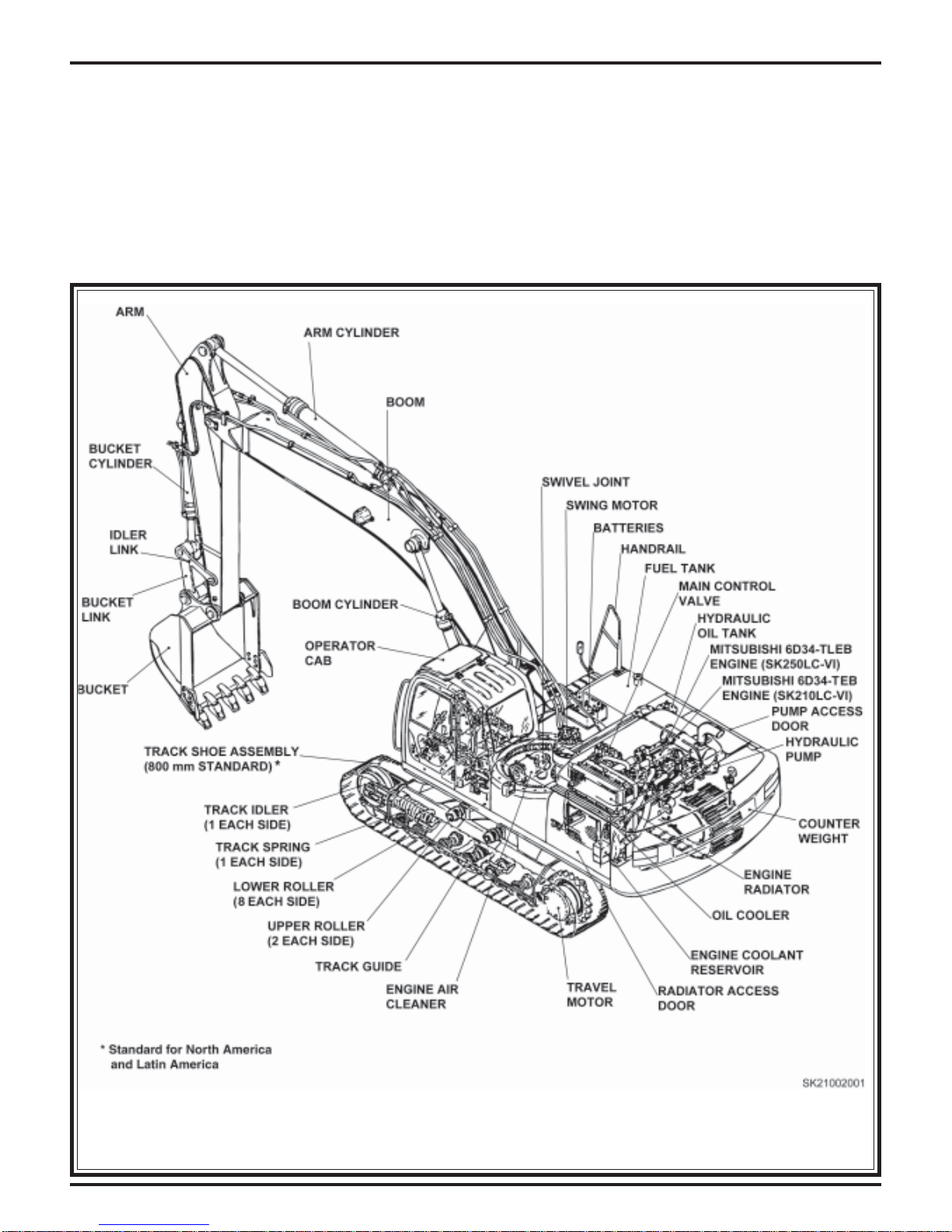
GENERAL MACHINE NOMENCLATURE
The Nomenclature drawing below (FIGURE
3.12),points out locations of major components of
the KOBELCO SK210(LC)-VI Hydraulic Excavator.
Study these areas and locate these component s on
the machine.Specific information regarding these
components are explained on the following pages of
this section.
Dynamic Acera 03/05 Rev. 05
Figure 3.12 SK210 VI
Page 3-17
MACHINE FAMILIARIZATION
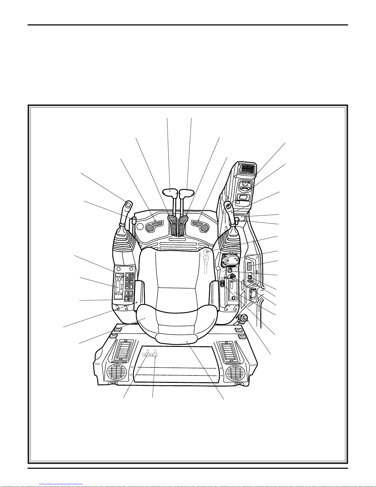
OPERATOR CAB NOMENCLATURE
The operator cab nomenclature (FIGURE 3.13),
points out the locations of operator controls of the
KOBELCO ED190-VI Hydraulic Excavator operator
cab.
LEFT TRAVEL LEVER
LEFT
TRAVEL
PEDAL
LEFT
LEFT HAND OPERATOR
CONTROL LEVER
(HORN SWITCH)
SAFETY LOCK
LEVER
(FOR HYDRAULICS)
FOOT REST
Study these areas and locate these component s on
the machine.Specific information regarding these
components are explained on the following pages of
this section.
RIGHT TRAVEL LEVER
RIGHT
TRAVEL
PEDAL
RIGHT
FOOT REST
GAUGE CLUSTER
POWER BOOST
RIGHT HAND
OPERATOR CONTROL
LEVER
LEFT SIDE
SWITCH PANEL
AIR-CONDITIONER
PANEL
BLADE CONTROL
SWITCH
ARM REST
OPERATORS SEAT
(3 WAY ADJUSTABLE)
ASH-TRAY
24V CIGARETTE
LIGHTER
ENGINE EMERGENCY
STOP CONTROL
DOZER BLADE CONTROL
SWITCH PANEL
(WIPER, WORKING LIGHT)
FAN
TEMP
E
F
F
/
D
E
R
O
D
M
THROTTLE
POTENTIOMETER
SWING FLASHER SWITCH
12V POWER SUPPLY
KEY SWITCH
RADIO (FM & AM)
Locally-procured parts
in European machines
SWITCH PANEL
(KPSS MODE, BUZZER STOP)
ENGINE MANUAL
CONTROL CABLE
KPSS RELEASE
SWITCH
Page 3-18
SWING PARKING BRAKE
RELEASE SWITCH
Figure 3.13 ED190 VI
HEAD REST
(ADJUSTABLE)
ED190opControlpanel
Dynamic Acera 03/05 Rev. 05
MACHINE FAMILIARIZATION
COMPONENT & CONTROLS NOMENCLA TURE
The following information provides a brief description and function of the components and
controls of the KOBELCO SK210(LC)-VI Hydraulic Excavator.
All personnel associated with this machine should
read and understand this information BEFORE
beginning any work with or on this equipment.
RIGHT HAND OPERATOR CONSOLE
1. Key Switch – FIGURE 3.14.a
The Key Switch is located on the right hand
operator console and has 5 operating functions.
a. “HEAT ”–This position is used for start-
ing the engine in cold climates.
b. “OFF ”–When Key is turned to this posi-
tion, the engine stops and electrical
power to the machine’s electrical systems is stopped after approximately 4
seconds.
c. “ACC ”–With key in the “ACC ”position
only the cigarette lighter, tuner and horn
will have power.
d. “ON”– When Key is in the ON position,
electrical power is supplied to all the
machine ’s electrical systems.
e. “ST ART ”–When key is turned to this po-
sition electrical power is supplied to the
starter solenoid causing the starter to
startthe engine. After engine starts key
should be released to go back to the
“ON ” position.
2. KPSS Mode Switch – FIGURE 3.14.b
The KPSS Mode Switch SK160~SK480 is located on the right hand operator console and has
3 operating functions. After starting the engine, the
mode switch defaults to the M for maximum power.
The operator can select an effective work mode
complyingwith the working conditions and working target from 3 modes. Each time the work mode
switch is pressed, the work mode indicator lamp
is switched from M, to A, then to B in that order.
FIGURE 3.14.a
SK160LC
KPSS MODE
SWITCH
ED190
Blade Runner
KPSS MODE SWITCH
KPSS Mode
FIGURE 3.14.b
NOTE
T o clear fault codes on the ED190 press the travel
speed change switch and the buzzer stop switch
at the same time. The new rocker switch for the
Mode/Buzzer Stop switch makes it impossible to
press both switches at the same time.
NOTE
SK480 A Assist mode reduces engine and
pump yield to approximately 90% of maximum
output.
Dynamic Acera 03/05 Rev. 05
a. M (Manual) mode
This mode senses the movement of control lever and is suitable for the heavy
load digging work giving priority to the
work load at high speed.
Page 3-19
MACHINE FAMILIARIZATION
b. A (Assist) mode SK160~SK330
Pressing the work mode selector switch
once changes to “A” or assist mode, located on the left of the three indicator lamps.
The mechatro controller analyzes the operator’s
pattern of joystick lever movement, and uses
“fuzzy logic” to set one of five machine operating parameters FIGURE 3.15.a
Control Mode
Results
Simple digging,
ditch digging, trench
box digging
Leveling,
slope finishing
( Contents on multidisplay
DIGGING
LEVELING
FIGURE 3.15.b
Spreading
SPREADING
Tamping
T AMPING
Traveling,
waiting time
STANDBY
FIGURE 3.15.a
Once the mechatro has analyzed the operators
joystick pattern, a moving graphic FIGURE
3.1 1.b (icon) flashes on the message display of
the monitor screen to show the operator which
assist mode is selected. Control is made easier
as the machine uses this pattern to “ASSIST” in
setting adequate pump and engine operation.
Operating efficiency increases FIGURE 3.15.c
without the operator even noticing.
LEVELING COMP ACTINGSCATTERING
Page 3-20
FIGURE 3.15.c
Dynamic Acera 03/05 Rev. 05

MACHINE FAMILIARIZATION
c. Breaker mode
Pressing the work mode selector twice
from “M” mode, changes the machine to
“B” or breaker mode. Located on the
right of M mode. See FIGURE 3.16.a. The purpose of this mode is to allow the operator to
quickly adjust the pump flow rates for various
attachments while sitting in the cab. When the
breaker or attachment is in operation the flow
volume is switched automatically to the operators preset pump flow. The flow returns to normal setting when the breaker or attachment is
not being used.
NOTE
The breaker flow is not set at the factory to deliver
maximum pump flow. T o change the flow rate to a
higher or lower setting see the following
information. “Gauge cluster will display pump flow
in metric units only .”
KPSS WORK MODE LAMP
SCREEN
CHANGE
SWITCH
FIGURE 3.16.a
W ARNING
Do not operate this machine unless you have
read and understand the instructions in the
OPERATORS MANUAL. Improper machine
operation is dangerous and could result in
injury or death.
1. With Safety Lock in the up or lock position,
place keyswitch to on position, do not start
engine. See FIGURE 3.16.b
2. Press the mode switch two times, the LCD
screen will display the set flow rate of the
breaker circuit. See FIGURE 3.17.c.
3. To change the pump flow (both pumps are
changed SK160 and up) move machine to
safe work area and turn keyswitch to off. Wait
ten seconds then procede.
Minimum / Max flow rate
1. Preparation
a. Keyswitch must be in off position for ten
seconds.
b. Turn keyswitch to on position do not start
engine, place safety lock in up position.
c. Press mode switch twice to select (B)
Breaker mode.
adjusting
procedure
FIGURE 3.16.b
NOTE
It is impossible to adjust flow rate after starting of
engine.
Step A-Max./Min. flow rate adjusting procedure
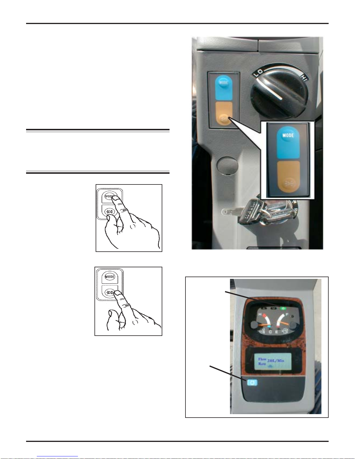
d. Press the screen change switch for 5 ~ 10
seconds and release. See FIGURE 3.16.a
the LCD screen displays the flow rate
stored in memory .
e. Press the mode switch once, see FIGURE
3.17.b flow rate value will increase in 10L/
min. increments. If mode switch is held
down for more than five seconds, flow rate
will increase rapidly . Release mode switch
when you have reached your desired
value.
Continued on next page -
Dynamic Acera 03/05 Rev. 05
Page 3-21
MACHINE FAMILIARIZATION
Min/Max flow rate adjustment - Cont.
f. Press the buzzer stop switch once, see
FIGURE 3.17.c. flow rate value will
decrease in 10L/min. increments. If buzzer
stop switch is held down for more than five
seconds, flow rate will decrease rapidly .
Release buzzer stop switch when you
have reached your desired value.
g. Press the screen change switch to store
the new flow rate value.
NOTE
If keyswitch is turned off before pressing the
screen change button and returning LCD screen
to OK new values will not be saved.
Press mode switch
in breaker flow rate
adjustment will
increase flow.
Press buzzer switch
in breaker flow rate
adjustment will
decrease flow.
FIGURE 3.17.a
FIGURE 3.17.b
FIGURE 3.17.c
KPSS work
mode lamp
Screen
change
switch
Page 3-22
FIGURE 3.17.d
Dynamic Acera 03/05 Rev. 05
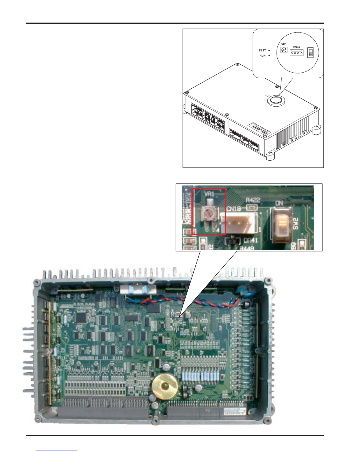
Auxiliary Flow Control Adjustment Potentiometer - (VR1 Trimmer)
Maximum / Minimum VR1 overide Protection - Pre minor change SK160~SK480 only
Located inside the mechantro controller on the
main circuit board is a trimmer dial VR1 which
will override the screen preset flow setting procedures. Not only will this feature provide protection
for equipment in “A” or “M” modes, it can also be
used to dial in flows less than which is stored in
memory of “B” mode.
This Flow control protection can be used to protect “auxiliary hydraulic circuit” but will not limit main
excavator boom,arm,bucket swing or travel
speed.Only the auxiliary attachment flow is controlled through the setting. See FIGURE 3.13.d.
Proper Adjustment thru the VR1 trimmer is
achieved by installing a proper flow meter in Series with the auxiliary attachment and after the
proper axillary attachment pressure has been
adjusted thru that circuit’s relief cartridge then insert a small flat blade screwdriver into the VR1
trimmer and adjust either clockwise or counter
clockwise for increased or decreased pump flow.
FIGURE 3.13.d
Note: Machine is shipped from the factory with
the VR1 trimmer set between 30%~ 95% of flow.
Dynamic Acera 03/05 Rev. 05
Page 3-23
MACHINE FAMILIARIZATION
3. Buzzer Stop Switch – FIGURE 3.18.a
When the engine coolant temperature
is too high, or various sensors of
mechatro controller (self-diagnosis)
fail, the alarm sounds intermittently . T o
stop thesound, press the buzzer stop button.
NOTE
• Buzzer sounding due to engine cooling water
temperature rise can not be stopped.
• The buzzer sounding, because the preheat
complete and E/G oil pressure are displayed,
stops by turning the key switch OFF.
SK160LC
KPSS MODE
SWITCH
ED190
Blade Runner
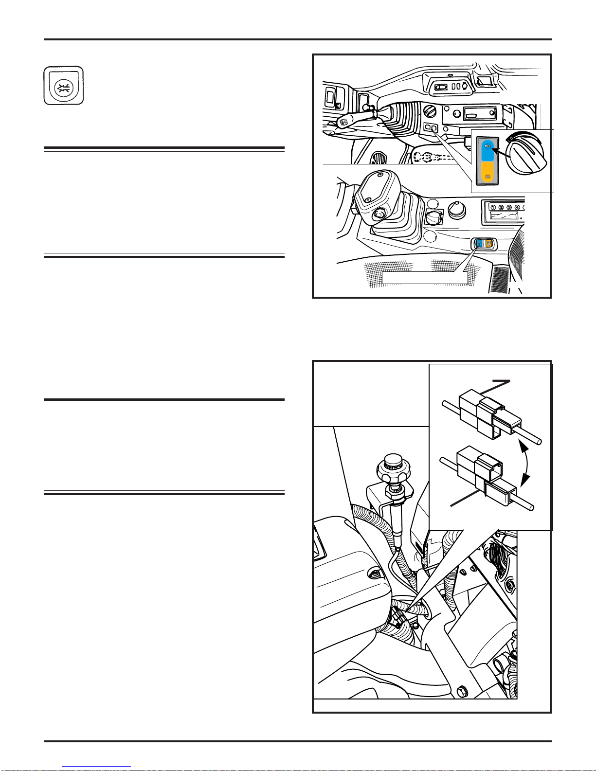
4. Throttle Potentiometer – FIGURE 3.18.A
The throttle potentiometer’s located on the
right hand operator console and controls
engine RPM. When the throttle potentiometer is rotated to right or left position it increases or decreases engine rpm and maintains engine at the programed RPM for that
particular position on the dial.
NOTE
In operation, when all pilot controls are in the
nuetral position for more than three seconds,
and the engine RPM is above 1050, the auto
excel reduces the engine speed to 1050.
Manual Auto Accel Over ride Procedure:
Auto accel release condition
1. Place the safety lever in the up and lock position.
KPSS MODE SWITCH
FIGURE 3.18.a
Normal position
Auto-acel. ON
Maintenance position.
Auto-acel disconnected
KPSS Mode
2. Located the one pin connector for the auto
acceleration function behind the operators
right hand console see FIGURE 3.18.b.
3. Change the position of the connector as in
indicated in FIGURE 3.18.b.
Page 3-24
Autoaccelconnector
FIGURE 3.18.b
Dynamic Acera 03/05 Rev. 05
 Loading...