

Kobelco KNW Series, KNWA00 Instruction Manual
MODEL#: SERIAL#:
INSTRUCTION MANUAL
KOBELCO is the international trademark found on all products of KOBE STEEL, LTD.
MODEL:
KNWA00
RECORD OF CHANGE H
KIMA00H1 (0204)

SAFETY PRECAUTIONS
Safety notices, marked with this symbol, are used in this
publication to emphasize that a hazardous condition exists that
could cause personal injury and/or damage to the equipment.
1. Read and understand the contents of this manual before installing,
operating or maintaining the compressor.
2. Electricity and compressed air are dangerous. When performing
maintenance or service work, make absolutely sure the electrical supply is
disconnected and locked out. The discharge air lines service valve
(customer furnished) must be closed and the compressor relieved of all
internal pressure. DO NOT rely on the discharge air line check valve.
3. Compressed air from this unit must not be used for breathing or food
processing without adequate filtering and monitoring to meet OSHA 29
CFR 1910 or FDA 21 CFR 178.3570.
4. Do not allow flammable, toxic or corrosive gases to enter the air inlet
system or electrical devices.
5. Never attempt to work on compressor or remove guards, panels,
covers, shields, etc. while the compressor is in operation.
6. Periodically confirm that all safety and shutdown devices are operating
properly.
7. Do not override any safety or shutdown device.
8. Make certain all associated pipe and equipment beyond this
compressor is compatible with maximum pressures and temperatures to
be encountered during normal and adverse operation. Do not use plastic
pipe in the compressed air system.
9. Keep doors closed during normal operation. The noise level inside
cabinet exceeds 90 decibels (dbA) and the operating temperature of some
components is sufficient to burn the skin.
10. Never assume it is safe to work on the compressor because it is not
operating. Many installations have automatic start/stop controls, and the
compressor may start at any time.
KIMA00H1 (0204)

TABLE OF CONTENTS
1. GENERAL DESCRIPTION................. 1 5.2 Programmable Logic
1.1 Compressor................................ 1 Controller.................................... 27
1.2 Compressed Air Flow................. 3 5.2.1 CPU................................. 27
1.3 Cooling Air Flow......................... 5 5.2.2 PLC Status LED’s............ 29
1.4 Oil Flow....................................... 5 5.2.3 PLC Inputs....................... 29
1.5 Capacity Control System............ 7 5.2.4 PLC Outputs.................... 29
1.5.1 Unloaded, Off...................7 5.2.5 PLC Analog Inputs........... 31
1.5.2 Loaded, Running............. 7 5.2.6 Expansion Module
1.5.3 Unloaded, Running.......... 7 Replacement....................31
1.6 Monitoring and Limiting 5.3 Motor Starter............................... 31
Devices....................................... 7
1.7 Alerts........................................... 9 6. MAINTENANCE.................................. 33
1.8 Shutdowns.................................. 9 6.1 Daily............................................ 33
6.2 Weekly........................................ 33
2. INSTALLATION...................................13 6.3 Monthly........................................33
2.1 Inspection....................................13 6.4 Yearly.......................................... 33
2.2 Handling...................................... 13 6.5 Two Year.....................................35
2.3 Foundation.................................. 13 6.6 Lubrication.................................. 35
2.4 Location...................................... 13 6.7 Filter Maintenance...................... 37
2.5 Cooling Air.................................. 13 6.7.1 Dust Filters.......................37
2.6 Air Discharge Piping................... 15 6.7.2 Inlet Air Filter....................37
2.7 Air Receiver................................ 15 6.7.3 Lube Oil Filter...................37
2.8 Wiring.......................................... 17 6.7.5 Sump Breather.................37
3. START UP............................................ 19 SERVICE PARTS LIST.......................38
3.1 Pre-Start Up Check....................... 19
3.2 Initial Start Up................................19
7. STANDBY and STORED UNITS........ 39
4. OPERATING INSTRUCTIONS............ 21 7.1 Stand-by Compressors............... 39
4.1 Starting the Compressor............... 21 7.2 Short Term Storage.................... 39
4.2 Stopping the Compressor............. 21 7.3 Long Term Storage.................... 39
4.2.1 Manual Stop.......................21
4.2.2 Automatic Stop.................. 23
4.3 Normal Operating Conditions........23 8. PROBLEM SOLVING......................... 40
Problem-Cause & Remedy
5. ELECTRICAL CONTROLS................. 25 Compressor................................ 40
5.1 Compressor Operator Panel PLC ............................................ 42
5.1.1 GT Terminal
Page Selection.................25 APPENDIX
5.1.2 Display Maintenance....... 27 A. Daily Operating Record ..................43
5.1.3 GT Terminal Options....... 27 B. Unit Dimensions .............................45
KIMA00H1 (0204)
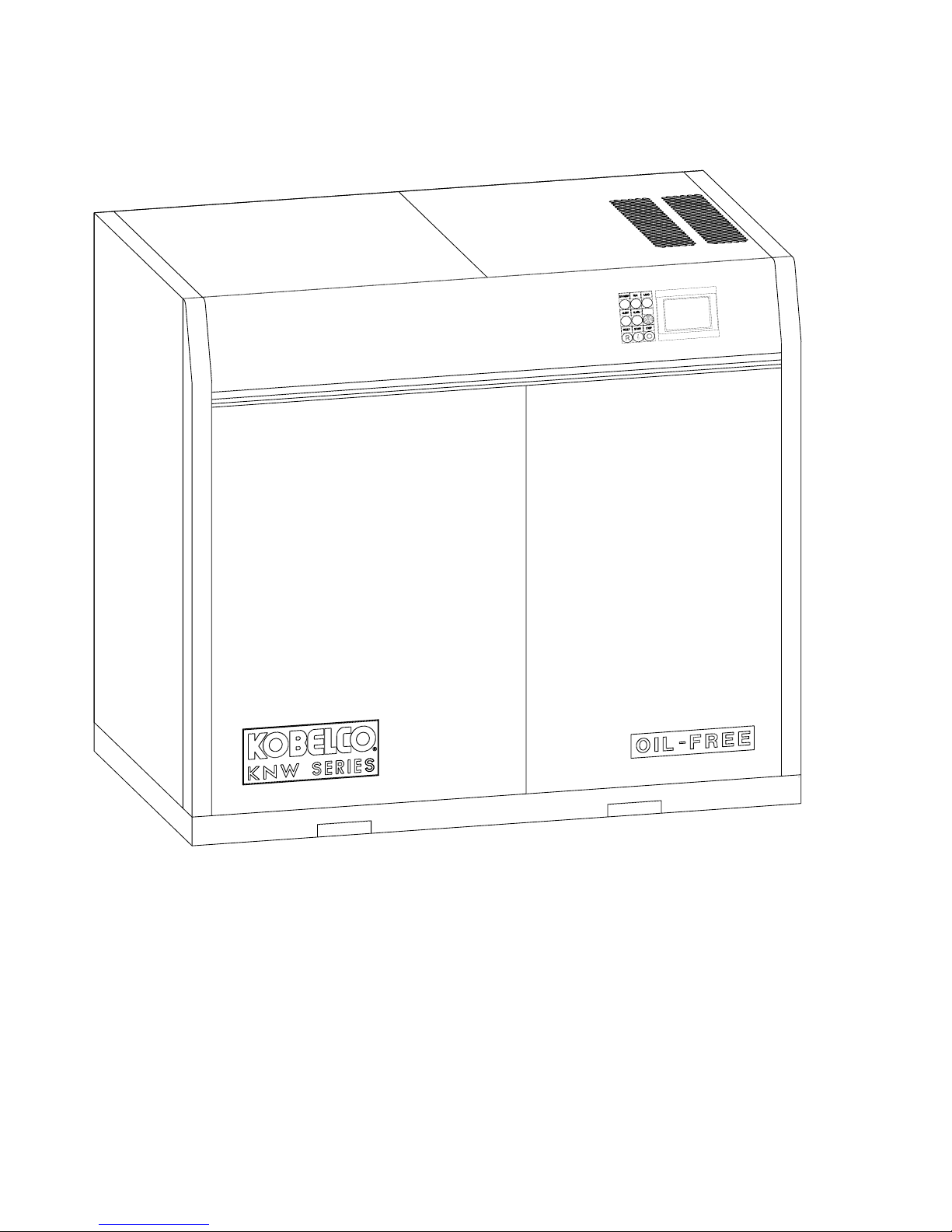
FIGURE 1 - KOBELCO KNW SERIES
MODEL A00 AIR COMPRESSOR
KIMA00H1 (0204)

1. GENERAL DESCRIPTION
1.1
Compressor
The Kobelco KNW Series air compressor is a heavy duty, two-stage,
rotary screw design that provides completely oil-free compressed air.
Oil-Free compressed air is guaranteed by a unique seal arrangement
that separates the bearings and gear chambers from the compression
section of each stage. The dual vent seal design insures that no oil or
its vapor can contaminate air that is being compressed.
The two-stage design provides higher output pressures at a lower
operating temperature than would be available from a single-stage
design. Both compressor stages are mounted on a heavy duty cast
iron gear case for permanent alignment. The stages are driven
through precision machined gears, selected for optimum operating
speed to maximize efficiency and reduce rotor thrust.
Timing gears are used to separate the rotors and to assist in reducing
thrust on the rotors and the rotor bearings, thus extending bearing life.
The Kobelco KNW Series Oil-Free Air Compressor is a complete
operating system. A flange-mounted permanently aligned drive motor,
intercooler, aftercooler, capacity control valve assembly, lube oil
system, compressor controls, and related accessories, are all
mounted inside a sound attenuating steel cabinet. All compressor
mounting points are vibration isolated. Flexible connections between
the compressor assembly and the cabinet insure that no vibration, and
its related noise, are transmitted to the cabinet. The result is a very
stable and quiet running assembly.
The KNW Series compressor features a separately driven oil pump for
drive gear, timing gear, and bearing lubrication. The lube oil pump
starts first, then, after a brief delay, the compressor drive motor starts.
Starting of the drive motor is delayed to allow pressurized lubrication
of the bearings and gears during acceleration of the compressor. The
pump is also timed to stop after the compressor. Oil pressure is
maintained while the compressor coasts to a stop. Maximum
component life is assured by thorough lubrication of moving
components.
Another feature of the KNW Series is the direct operating capacity
control valve and bleed-off system. This unique valve design provides
for extended service intervals and eliminates the need for a bleed-off
cooler.
The KNW Series Compressor Operator Panel is a state-of-the-art
control system combining robust industrial controls with leading edge
operator interface and programmable logic controller technology.
Exclusive to KNW Series compressors is the GT Terminal, a versatile
graphic touchscreen display with clear graphics and user-friendly
operation, showing all necessary compressor information in an easy to
understand format.
KIMA00H1 (0204)
1
COOLING
AIR OUTLET
AFTERCOOLER
AIR INLET
COOLING
AIR INLET
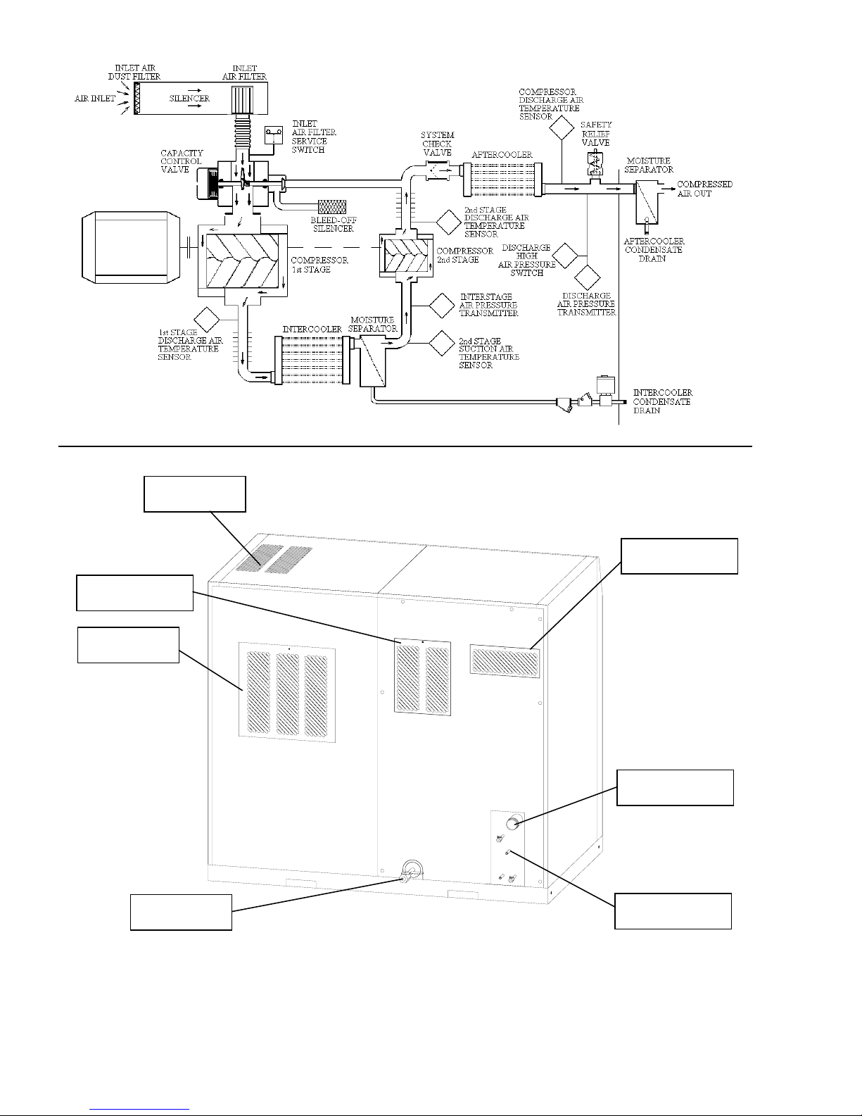
FIGURE 2 - COMPRESSED AIR FLOW DIAGRAM
COMPRESSOR
AIR INLET
COMPRESSED
AIR DISCHARGE
SUMP
OIL DRAIN
FIGURE 3 - BACK OF COMPRESSOR
2
CONDENSATE
DRAIN
KIMA00H1 (0204)

1.2
Compressed
Air Flow
(Figure 2)
Air to be compressed undergoes two stages of filtration before being
compressed. The air enters the cabinet through an opening that is
equipped with a dust filter. The air then passes through the air inlet
silencer, a duct that is lined with a sound absorbing material. Then
the air is drawn through a high efficiency air filter. Filtered air flows
through a flex connector, into the capacity control valve, and then into
the inlet of the compressor first stage.
The compressor first stage compresses the filtered air to
approximately 37 PSIG. The compressed air is discharged into the aircooled intercooler where it is cooled to approximately 115°F (46°C).
The cooled, compressed air then passes through the moisture
separator to remove any condensed moisture from the air stream
before entering the compressor second stage.
The compressor second stage compresses interstage air to the
system operating pressure as controlled by the pressure setting. The
hot compressed air then passes through the system check valve and
air-cooled aftercooler where it is cooled to within approximately 15°F
(8°C) of the ambient air temperature. An ASME safety valve is
downstream of the check valve. The compressed air exits the unit
into a moisture separator, where condensed moisture is removed
before the air enters the plant air system.
The compressed air circuit is monitored with the following discrete
devices:
a. Inlet air filter service switch
b. Discharge high air pressure switch
c. Discharge air safety relief valve
The Programmable Logic Controller, PLC, (ref. Section 5.2) monitors
the compressed air circuit for the following:
a. First stage discharge air temperature
b. Interstage air pressure
c. Second stage suction air temperature
d. Second stage discharge air temperature
e. Compressor discharge air pressure
f. Compressor discharge air temperature
The air temperatures are displayed on the GT Terminal. The PLC
continuously monitors for excessive heat, providing a warning if
temperatures approach the recommended maximum and a shutdown
if they reach the limit. The interstage pressure is monitored to provide
load/unload indication and to confirm capacity control valve operation.
The pressure at the compressor discharge is monitored to provide
load and unload pressure control and a high pressure alarm.
KIMA00H1 (0204)
3
AFTERCOOLER EXHAUST
AFTERCOOLER
AIR DUCT
AIR INLET
(REAR)
AIR DUCT
AIR
OUTLET
COOLING
FAN
OIL
COOLER
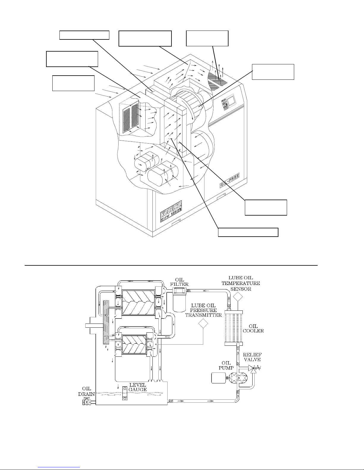
FIGURE 4 - COOLING AIR FLOW
INTERCOOLER
FIGURE 5 - LUBRICATION OIL FLOW DIAGRAM
4
KIMA00H1 (0204)

1.3
Cooling
Air Flow
(Figure 4)
A separate electric motor driven fan draws ambient air into the cabinet
through screens in the back panel. The screens are equipped with
dust filters. The air takes one of two flow paths. The first passes
directly through to the aftercooler and exhausts through the top of the
enclosure. In the second path, air enters near the motor, cools the
compressor motor and passes into the compressor section of the
cabinet. The air then goes through both the intercooler and oil cooler
which are mounted side by side. The fan draws all the air through the
exhaust chamber and out the top of the enclosure.
When the compressor unloads, hot air is discharged through the
bleed-off silencer, pulled through the fan and exhausted. A
temperature switch shuts down the compressor if the air temperature
inside the cabinet exceeds 150°F (65°C).
1.4
Lubrication
Oil Flow
(Figure 5)
Oil for bearing and gear lubrication is stored in a sump, in the lower
section of the main gear case/compressor housing. A sight glass,
located on the side of the oil sump, is used to monitor the oil level.
Lube oil is drawn from the sump by a separate motor driven oil pump.
An oil pump discharge relief valve is provided to maintain a constant
pressure for component lubrication by relieving excessive pressure
back to the suction of the pump.
Oil leaving the pump is cooled to approximately 28°F (15°C) above
ambient air temperature in the oil cooler and is then filtered before
entering an oil gallery on the rear of the compressor first stage. A
portion of the lube oil passes through a tube to an oil gallery on the
rear of the compressor second stage. Lube oil flows from the oil
galleries to the front of each stage to lubricate and cool the front
bearings and drive gears. Lube oil passes through internal passages
from the galleries to lubricate the rear bearings and the timing gears.
All lube oil drains back into the sump.
The lube oil circuit is monitored with the following discrete devices:
a. Sump oil level indicator.
b. Lube oil filter differential switch.
The Programmable Logic Controller, PLC, (ref. Section 5.2) monitors
the lubrication circuit for the following:
a. Lube oil pressure
b. Lube oil temperature
The oil temperature is displayed on the GT Terminal. The PLC
monitors the lube oil temperature. A warning is provided as the
temperature approaches the recommended maximum operating
temperature, and a shutdown if it reaches the limit. The lube oil
pressure is monitored for alarm shutdown if the oil pressure is too low
while the compressor is operating.
KIMA00H1 (0204)
5
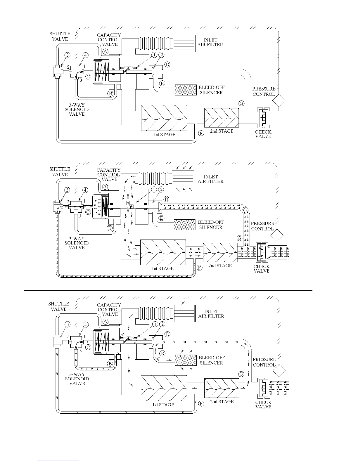
FIGURE 6 - UNLOADED, COMPRESSOR OFF
FIGURE 7 - LOADED, COMPRESSOR RUNNING
FIGURE 8 - UNLOADED, COMPRESSOR RUNNING
6
KIMA00H1 (0204)

1.5
Capacity
Control
System
The capacity control system consists of an inlet capacity control valve
with an integral bleed-off valve, a 3-way solenoid valve, and a shuttle
valve. Opening (loaded) and closing (unloaded) of the inlet valve is
controlled by the solenoid valve which is controlled by the PLC (ref.
Section 5.2). The PLC monitors compressor operating conditions and
system air pressure to determine when loaded or unloaded operation
is required.
1.5.1
Unloaded,
Off
(Figure 6)
1.5.2
Loaded,
Running
(Figure 7)
When the compressor is off, the spring in the capacity control valve
holds the inlet valve (1) closed and the bleed-off valve (2) open. The
solenoid valve (4) is deenergized. When the compressor is started
pressures at the 1st stage inlet (B) and interstage (F) are both
negative, keeping the capacity control valve in the unloaded position.
The compressor remains unloaded until the main drive motor reaches
full speed, and lube oil pressure reaches 10 psig. After the
compressor reaches full speed and oil pressure is established, the
solenoid valve (4) is energized, the capacity control valve operating
chamber (C) is disconnected from 1st stage inlet vacuum and is
vented to atmosphere (A) through the shuttle valve (3). Vacuum on
the spring side of the operating chamber piston helps pull the inlet
valve (1) open and closes the bleed-off valve (2). The inlet valve (1) is
a butterfly valve which rotates and is operated by a slider on the
capacity control valve shaft.
Air is now drawn into the compressor stages through the inlet air filter,
compressed, and discharged through the check valve to the air piping
system. As air is compressed interstage pressure (F) increases,
transferring the shuttle valve (3) and pressurizing the operating
chamber (C), keeping the capacity control valve open.
1.5.3
Unloaded,
Running
(Figure 8)
1.6
Monitoring
and Limiting
Devices
(Figures 9-11)
System pressure is monitored by a pressure sensor on the discharge
air piping. When the discharge pressure reaches the upper limit of the
desired operating range, the solenoid valve is de-energized, depressurizing the operating chamber (C). The spring closes the inlet
valve (1) and opens the bleed-off valve (2).
When unloaded a very slight amount of air is drawn through the inlet
valve (1) to cool the compressor during unloaded operation. 2nd stage
discharge air (G) is vented (D) to atmosphere (E) out of the bleed-off
silencer. The check valve prevents system air pressure from
pressurizing the compressor.
The compressor assembly is equipped with the following monitoring
devices:
a. Interstage air pressure transmitter. Monitors air pressure at the
intercooler outlet. The pressure is shown on the GT Terminal
(figure 10). Indicates condition of the intercooler and the
compressor stages.
b. Outlet air pressure transmitter. Monitors air pressure at the
aftercooler outlet connection to plant air system. Pressure is
shown on the GT Terminal (figure 10). Indicates condition of the
aftercooler and the compressor stages.
KIMA00H1 (0204)
7
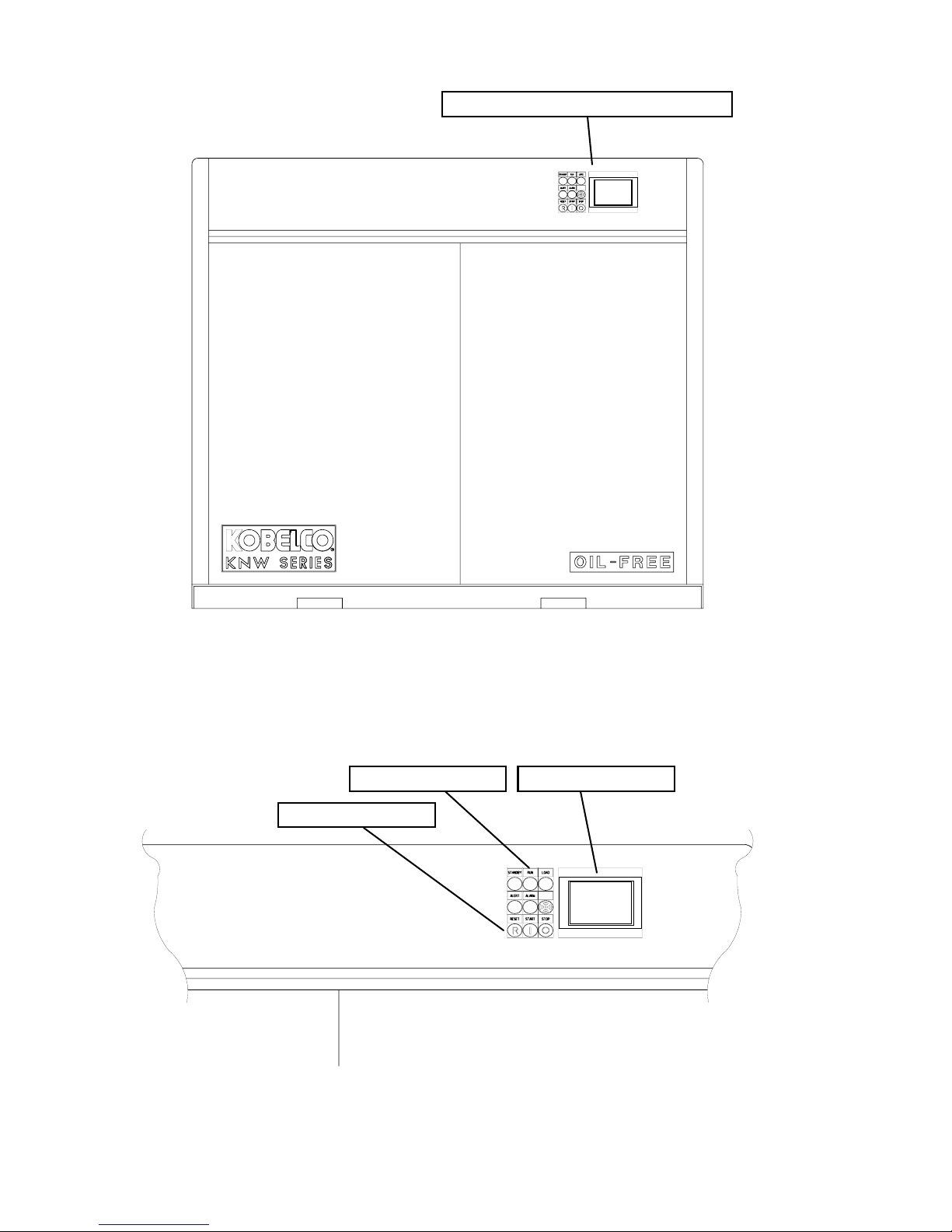
COMPRESSOR OPERATOR PANEL
FIGURE 9 - COMPRESSOR FRONT VIEW
PILOT LIGHTS
PUSHBUTTONS
GT TERMINAL
FIGURE 10 - COMPRESSOR OPERATOR PANEL
8
KIMA00H1 (0204)

(cont.)
1.6
Monitoring
and Limiting
Devices
c. Lube oil pressure transmitter. Monitors lube oil pressure at the
last bearing oil nozzle. Pressure is shown on the GT Terminal
(figure 10). Indicates condition of the lube oil system, filter, and
the setting of the relief valve.
d. First stage discharge air temperature sensor. Temperature is
shown on GT Terminal (figure 10). Indicates condition of the
compressor first stage.
e. Second stage inlet air temperature sensor. Temperature is
shown on the GT Terminal (figure 10). Indicates condition of the
intercooler.
f. Second stage discharge air temperature sensor. Temperature is
shown on the GT Terminal (figure 10). Indicates condition of the
compressor second stage.
g. Lube oil temperature sensor. Temperature is shown on the GT
Terminal (figure 10). Indicates condition of the oil cooler.
h. Aftercooler discharge air temperature sensor. This is the
temperature of the air delivered to the air out service connection,
and is shown on the GT Terminal (figure 10). Indicates condition
of the aftercooler.
i. Total running time is shown on the GT Terminal (figure 10).
j. Total loaded time is shown on the GT Terminal (figure 10). An
accumulated count of loaded hours assists in tracking air usage
and available excess capacity.
k. Normal condition indication lights, on the Compressor Operator
Panel:
1. Standby
2. Run
3. Loaded
A lamp test is available using the GT Terminal, which tests all
indicating lights on the control panel, and the alarm beeper, if power is
on. This test does not affect normal compressor operation.
1.7
Alerts
KIMA00H1 (0204)
A blue ALERT light, and an appropriate message on the GT Terminal,
indicates that service is required or that a temperature prealarm exists
(temperature is approaching the shutdown point). In addition, an
audible alarm sounds when an alert occurs. The alarm may be
silenced without resetting the indication.
The GT Terminal indicates the following conditions as an ALERT:
a. Service inlet air filter. Indicates that the inlet air filter or the dust
filters are dirty, filter pressure drop exceeds 25 “H2O
b. Service oil filter. Indicates that the lube oil filter is dirty, filter
pressure drop exceeds 15 PSID.
c. Compressor service required. Indicates that 2 years have
elapsed since start-up, or the capacity control valve has cycled
1,000,000 times. Service must be scheduled.
d. Temperature prealarm (applies to all temperatures monitored).
Indicates that a temperature is approaching the shutdown point.
Refer to the appropriate paragraph of section 1.8 for details of
each monitored temperature. See page 22 for setpoint table.
9
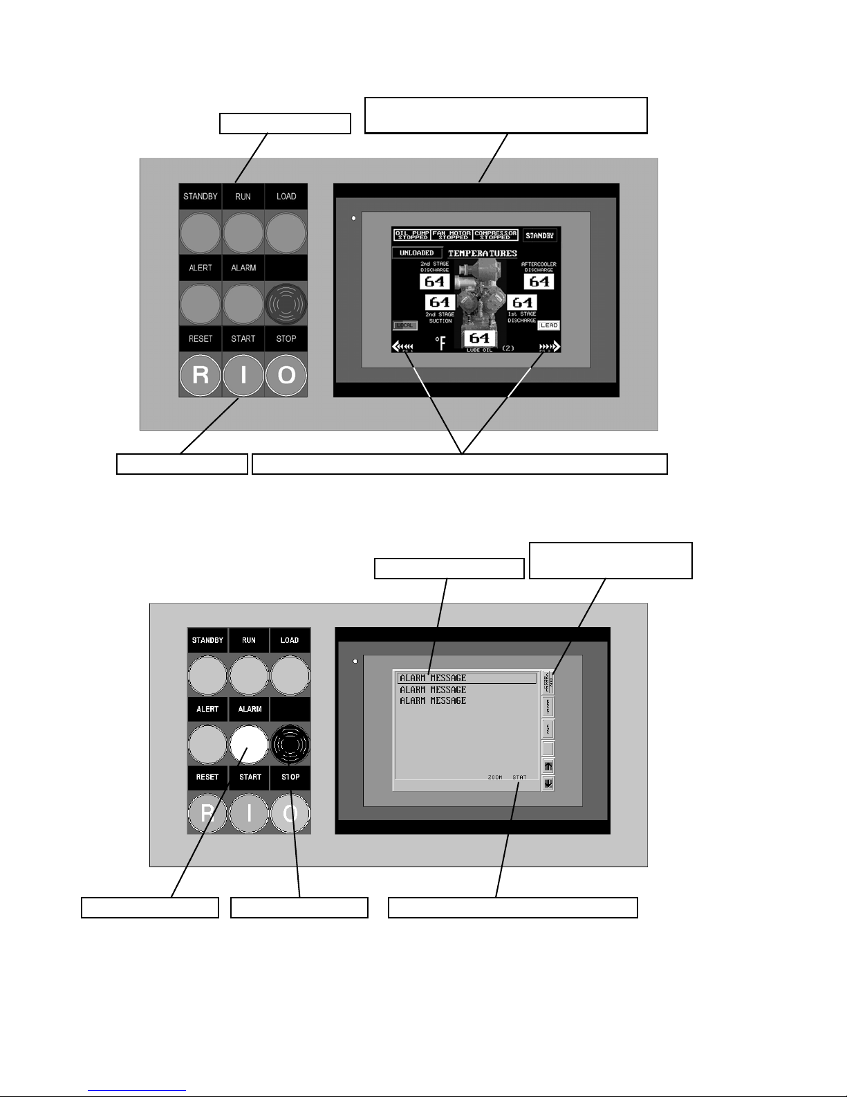
PILOT LIGHTS
GT-TERMINAL
GRAPHIC TERMINAL W/ TOUCHSCREEN
PUSHBUTTONS
FIGURE 11 - COMPRESSOR OPERATOR PANEL
PRESS ARROWS TO CHANGE DISPLAY SCREENS
PRESS “ACK” TO
ALARM MESSAGE
SILENCE BEEPER
ALARM LIGHT
ALARM BEEPER
FIGURE 12 - ALARM DISPLAY
10
PRESS “STAT” FOR ALARM DETAILS
KIMA00H1 (0204)

1.8
Shutdowns
Shutdown conditions are indicated by a red ALARM light on the
control panel, and an appropriate message on the graphic display. In
addition, an audible alarm sounds when an alarm occurs. The alarm
beeper may be silenced by pressing ACK/Bell Cancel on the alarm
page. The Bell Cancel does not reset the alarm. A "DRY" relay
contact is provided as a combined signal for remote indication if any
alarm occurs. A table of setpoints is located on page 22.
The GT Terminal indicates the following shutdown conditions:
a. High 1st Discharge Air Temperature (Shutdown)
Warning: HOT 1st Discharge (Prealarm)
Indicates a problem with the first compressor stage.
b. Warning: HOT 2nd Suction (Prealarm)
High 2nd Suction Air Temperature (Shutdown)
Indicates a problem with the intercooler or cooling air flow.
c. Warning: HOT 2nd Discharge (Prealarm)
High 2nd Discharge Air Temperature (Shutdown)
Indicates a problem with the second compressor stage or a
problem with the intercooler.
d. Warning: HOT Air Discharge (Prealarm)
High Discharge Air Temperature (Shutdown)
Indicates a problem with the aftercooler or cooling air flow.
e. Warning: HOT Lube OIL (Prealarm)
High Lube Oil Temperature (Shutdown)
Indicates a problem with the lube oil cooling system.
f. Low Lube Oil Pressure
Indicates low lube oil level in sump, lube oil pump failure, fouled
cooler or piping, clogged oil filter, or improper setting of the relief
valve.
g. Lube Oil Pump Motor Overload
Indicates continued over-current operation of the oil pump motor,
problem with lube oil pump or motor, or high oil pressure.
h. Cooling Fan Motor Overload
Indicates continued over-current operation of the cabinet cooling
fan motor, problem with fan or motor. Also check for obstructed
air flow into or out of the cabinet.
i. Compressor Drive Motor Overload
Indicates continued over-current operation of the drive motor for
the compressor, excessive discharge pressure or a problem with
either compressor stage.
j. High Cabinet Temperature
Indicates an obstruction of the cooling air flow.
k. High Discharge Air Pressure
Indicates a problem with the capacity control system.
l. Main Starter Failure
Indicates a problem with the main starter or controls.
KIMA00H1 (0204)
11
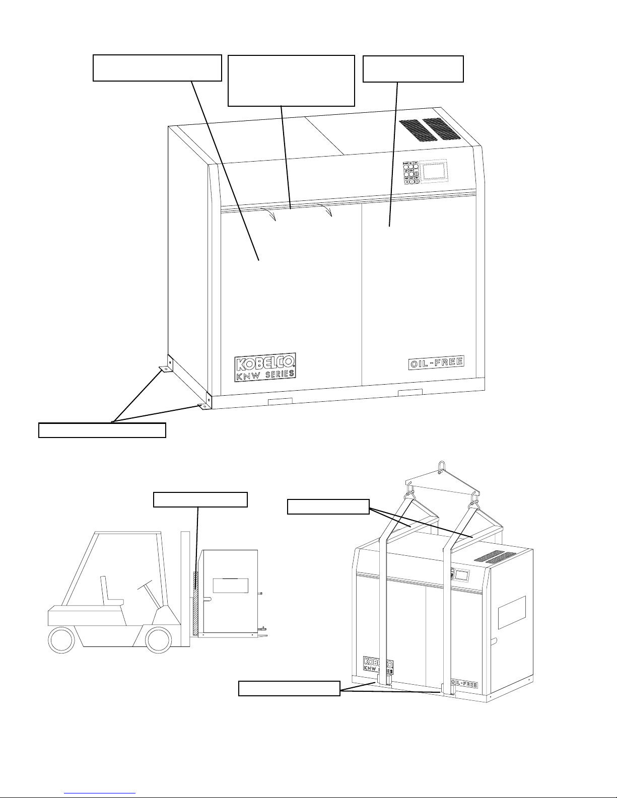
COMPRESSOR SECTION
ACCESS PANEL
TO OPEN PANELS
FOR INSPECTION,
PULL OUT TOP EDGE
THEN LIFT PANEL UP
STARTER SECTION
ACCESS PANEL
MOUNTING BRACKETS
FIGURE 14
SPACER BLOCKS
FIGURE 13
SPREADERS
SPACER BLOCKS
FIGURE 15
12
KIMA00H1 (0204)
2. INSTALLATION
2.1
Inspection
(Figure 13)
2.2
Handling
(Figures
14 & 15)
2.3
Foundation
2.4
Location
The unit should be inspected for damage immediately upon receipt
from the carrier and any claims should be made to the delivery carrier
immediately.
The compressor unit is equipped with forklift slots for ease in handling.
Spacer blocks should be placed between the compressor and forklift
mast to insure the cabinet will not be damaged during handling.
When handling the unit with an overhead crane, the lifting straps or
chains should pass through the forklift slots. Spacers and spreader
bars should be utilized to avoid damage to the enclosure.
The compressor and motor assembly are vibration isolated from the
housing and base plate, additional isolation is not required. The
assembly should be mounted on a level, horizontal floor. Holes are
provided on each end of the compressor for installing bolt down
brackets.
The unit should be installed indoors in a clean, well ventilated area,
free from excessive dust or dripping liquids. Do not install in an area
where chlorine gas, hydrogen sulfide gas, sulfur dioxide gas, highly
concentrated ozone, or any other toxic, corrosive or flammable gasses
are present.
2.5
Cooling
Air
(Figure 17)
WARNING:
The compressor shall not be located where potentially
explosive atmospheres may occur. The compressor and controls are
not rated for installation in hazardous (classified) locations.
Any contaminates in the atmosphere will be compressed along with
the air, therefore, it is important to provide a source of clean intake air.
An external source of clean inlet air to the compressor may need to be
provided.
The machine must be protected against freezing and excessive
ambient temperatures.
For ease of panel removal and maintenance provide ample clearance
around the compressor. A minimum of four feet is required in front of
the compressor. At least three feet is recommended for each end and
for the back.
The compressor should be located where sufficient ventilation is
available to cool the compressor. The cooling air inlet and discharge
must not be blocked. The warm air exiting the cooling air outlet must
be prevented from being drawn into the cooling air inlet. Ventilation
may need to be provided if the room in which the compressor is
installed exceeds 104°F (40°C) during compressor operation.
Air ducts may be connected to air inlets or outlets if desired. However
ducts must be sized to permit no more than 1” H2O restriction at full
flow.
KIMA00H1 (0204)
13
 Loading...