

KOBE IS2436GSF-1, IS2442GSF-1 Installation Instructions And Operation Manual
KOBE Brand Range Hoods
Model No. / Nos de modèles / Modelo No.
IS2436GSF-1
IS2442GSF-1
IS-124 SERIES – 5” HEIGHT
“ISLAND GLASS CANOPY WITH LCD SCREEN”
INSTALLATION INSTRUCTIONS
INSTRUCCIONES DE INSTALACIÓN
AND OPERATION MANUAL
MANUEL D'INSTALLATION
ET MODE D'EMPLOI
Y MANUAL DE OPERACIÓN

[ENGLISH] ................................................................................................................... 2
[FRENCH] .................................................................................................................. 27
[SPANISH] ................................................................................................................. 50

READ BEFORE INSTALLATION
NO RETURN, NO REFUND, NO EXCHANGE IF:
1. PRODUCT HAS BEEN INSTALLED
2. KNOCK-OUT HOLES HAVE BEEN PUNCTURED
3. MISSING ORIGINAL PACKAGING MATERIAL AND/OR
PARTS
IMPORTANT
READ THIS
FIRST
1. Carefully check all contents of packages;
2. Thoroughly inspect the unit for any cosmetic damages or
defects;
3. Test the unit before installation;
4. Have a certified contractor/electrician do the installation.
IF THERE IS ANY PROBLEM:
1. DO NOT INSTALL THE UNIT AND KEEP ALL ORIGINAL
PACKAGING MATERIAL.
2. Have your original proof of purchase and product serial number
ready.
3. Call 1-877-BUY-KOBE (289-5623); or e-mail to
info@koberangehoods.com to report the problem.
1

IMPORTANT SAFETY INSTRUCTIONS ..................................................................... 3
COMPONENTS OF PACKAGE ................................................................................... 5
INSTALLATION ............................................................................................................ 6
OPERATION INSTRUCTIONS .................................................................................. 10
MAINTENANCE ......................................................................................................... 13
SPECIFICATIONS ..................................................................................................... 15
MEASUREMENTS & DIAGRAMS ............................................................................. 16
PARTS LIST............................................................................................................... 18
CIRCUIT DIAGRAM ................................................................................................... 20
TROUBLE SHOOTING .............................................................................................. 21
WARRANTY .............................................................................................................. 22
PRODUCT REGISTRATION...................................................................................... 24
CONTENTS
[ENGLISH]
- READ AND SAVE THESE INSTRUCTIONS -
- READ ALL INSTRUCTIONS CAREFULLY BEFORE STARTING -
AL L W IR IN G MU S T BE D O N E B Y A P R O FE SS IO N A L A ND I N
AC CO RD AN C E W I T H NA TI O NA L A N D L OC AL E L EC T R I CA L CO DE S
2
IMPORTANT SAFETY INSTRUCTIONS
NOTE
-
This warranty is invalid without an authorized agent’s receipt or if unit is
damaged due to misuse, poor installation, improper use, mistreatment,
negligence or any other circumstances beyond the control of KOBE
RANGE HOODS authorized agents. Any repair carried out without the
supervision of KOBE RANGE HOODS authorized agents will
automatically void the warranty.
- KOBE RANGE HOODS will not be held responsible for any damages to
personal property or real estate or any bodily injuries whether caused
directly or indirectly by the range hood.
- PLEASE READ THIS SECTION CAREFULLY BEFORE INSTALLATION -
WARNING: TO REDUCE THE RISK OF FIRE, ELECTRIC SHOCK OR PERSONAL
INJURY, OBSERVE THE FOLLOWING:
1) Installation and electrical wiring must be done by qualified professionals and in accordance with all
applicable codes and standards, including fire-rated construction.
2) When cutting or drilling into wall or ceiling, be careful not to damage electrical wiring or other hidden
utilities.
3) Ducted fans must be vented to the outside.
a) Before servicing or cleaning unit, open the light panel and SWITCH POWER OFF AT SERVICE
PANEL.
b) Clean all grease laden surfaces frequently. To reduce the risk of fire and to disperse air
properly, make sure to vent air outside. DO NOT vent exhaust air into wall spaces, attics, crawl
spaces or garages.
WARNING: TO REDUCE THE RISK OF PERSONAL INJURY IN THE EVENT OF A
RANGE TOP GREASE FIRE:
- Keep all fan, baffle/spacer/filter/oil tunnel/oil container and grease-laden surfaces clean. Grease
should not be allowed to accumulate on fan, baffle/spacer/filter/oil tunnel/oil container.
- Always turn hood ON when cooking.
- Use high settings on cooking range ONLY when necessary.
- Do not leave cooking range unattended when cooking.
- Always use cookware and utensils appropriate for the type and amount of food prepared.
- Use this unit only in the manner intended by the manufacturer.
- Before servicing, switch power off at service panel and lock service panel (if possible) to prevent
power from switching on accidentally.
- Clean ventilating fan frequently.
3
What to Do In The Event Of a Range Top Grease Fire
• SMOTHER FLAMES with a tight fitting lid, cookie sheet, or metal tray, and then turn off the burner.
KEEP FLAMMABLE OR COMBUSTIBLE MATERIAL AWAY FROM FLAMES. If the flames do not
go out immediately, EVACUATE THE AREA AND CALL THE FIRE DEPARTMENT or 911.
• NEVER PICK UP A BURNING PAN – You May Get Burned.
• DO NOT USE WATER, including wet dishcloths or towels – a violent steam blast will result.
• Use an extinguisher ONLY if:
a) You have a Class A, B, C extinguisher and know how to operate it.
b) The fire is small and contained in the area where it started.
c) The fire department has been called.
d) You can fight the fire with your back to an exit.
What to Do If You Smell Gas
- Extinguish any open flame.
- Do not try to turn on the lights or any type of appliance.
- Open all doors and windows to disperse the gas. If you still smell gas, call the Gas Company and
Fire Department right away.
CAUTION
1) For general ventilation use only. Do not use to exhaust hazardous or explosive materials and
vapors.
2) To reduce the risk of fire, use only metal ductwork. Sufficient air is needed for proper combustion
and exhausting of gases through the flue (chimney) to prevent back drafting.
3) Follow the heating equipment manufacturer’s guideline and safety standards such as those
published by the National Fire Protection Association (NFPA), and the American Society for
Heating, Refrigeration and Air Conditioning Engineers (ASHRAE), and code authorities.
4) Activating any switch on may cause ignition or an explosion.
5) Due to the size and weight of this hood, a two person installation is recommended.
ELECTRICAL SHOCK HAZARD – Can result in serious injury or
death. Disconnect appliance from electric power before servicing.
If equipped, the fluorescent light bulb contains small amounts of
mercury, which must be recycled or disposed of according to
Local, State, and Federal Codes.
4
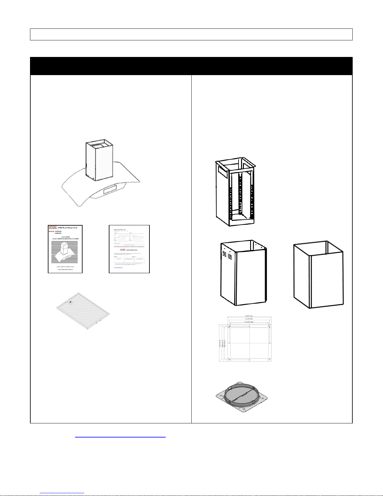
COMPONENTS OF PACKAGE
MODEL NO. IS2436GSF-1
MODEL NO. IS2442GSF-1
KOBE Range Hoods – 1
Instructions Manual – 1
Warranty Card – 1
Aluminum Mesh Filter – 2
Telescopic Stack – 1
Inner Duct Cover – 1
Outer Duct Cover – 1
Mounting Template – 1
Exhaust Plate w/ screw package – 1
(Must keep all material for returns or refunds)
OPTIONAL RECIRCULATING KIT AVAILABLE. FOR MORE INFORMATION, PLEASE VISIT OUR
WEBSITE WWW.KOBERangeHoods.com OR CONTACT KOBE RANGE HOODS AT (626) 775-8880.
5
INSTALLATION
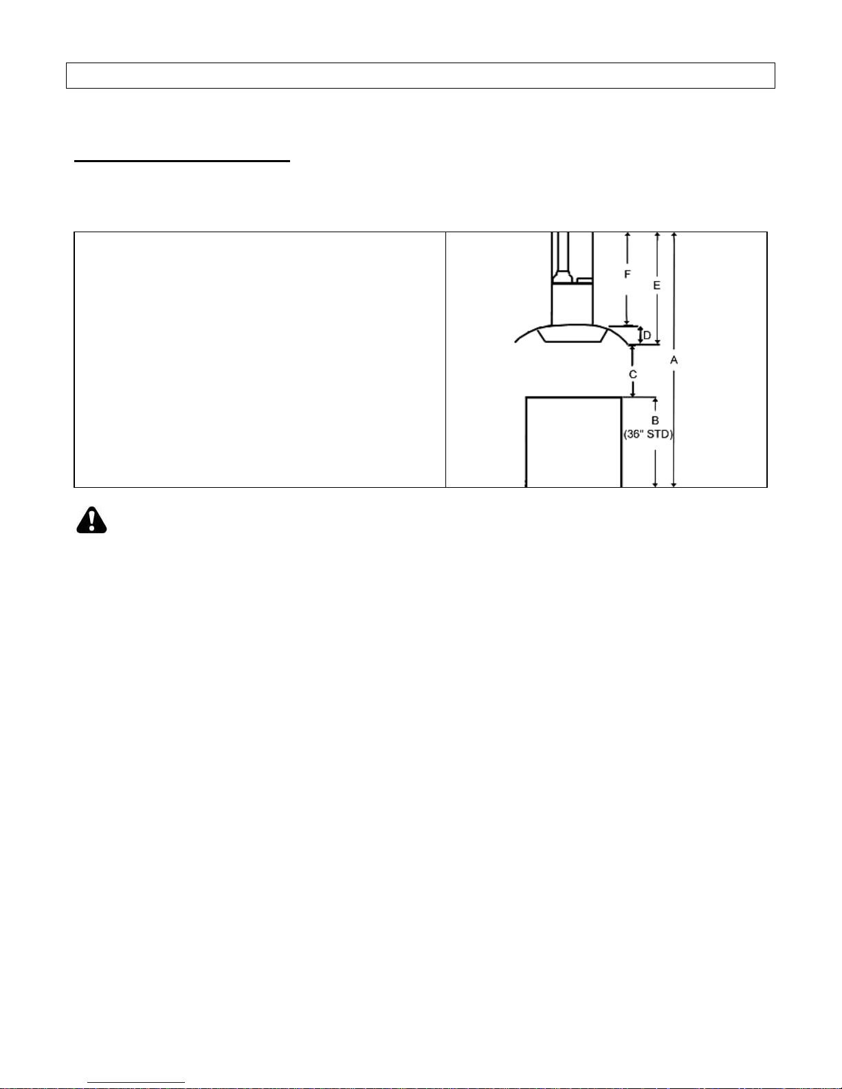
TABLE 1
A = Height of Floor to Ceiling
B = Height of Floor to Counter Top
(Standard: 36”)
C = Preferred Height of Counter Top to Hood
Bottom (Recommended 30” to 36”)
D = Height of Hood
E = Height of the Hood Installation
[A – (B+C)]
F = Height of Duct Cover
[E – D]
PLEASE READ ENTIRE INSTRUCTIONS BEFORE PROCEEDING
Calculation before Installation
To calculate installation, please refer to TABLE 1. (All calculations are in inches.)
SAFETY WARNING
HOOD MAY HAVE VERY SHARP EDGES; PLEASE WEAR PROTECTIVE GLOVES IF
REMOVING ANY PARTS FOR INSTALLING, CLEANING OR SERVICING.
NOTE: BE CAREFUL WHEN USING ELECTRICAL SCREWDRIVER, DAMAGE TO THE HOOD
MAY OCCUR.
6
Preparation before Installation
Advance Planning
NOTE: TO AVOID DAMAGE TO YOUR HOOD,
PREVENT DEBRIS FROM ENTERING
THE VENT OPENING.
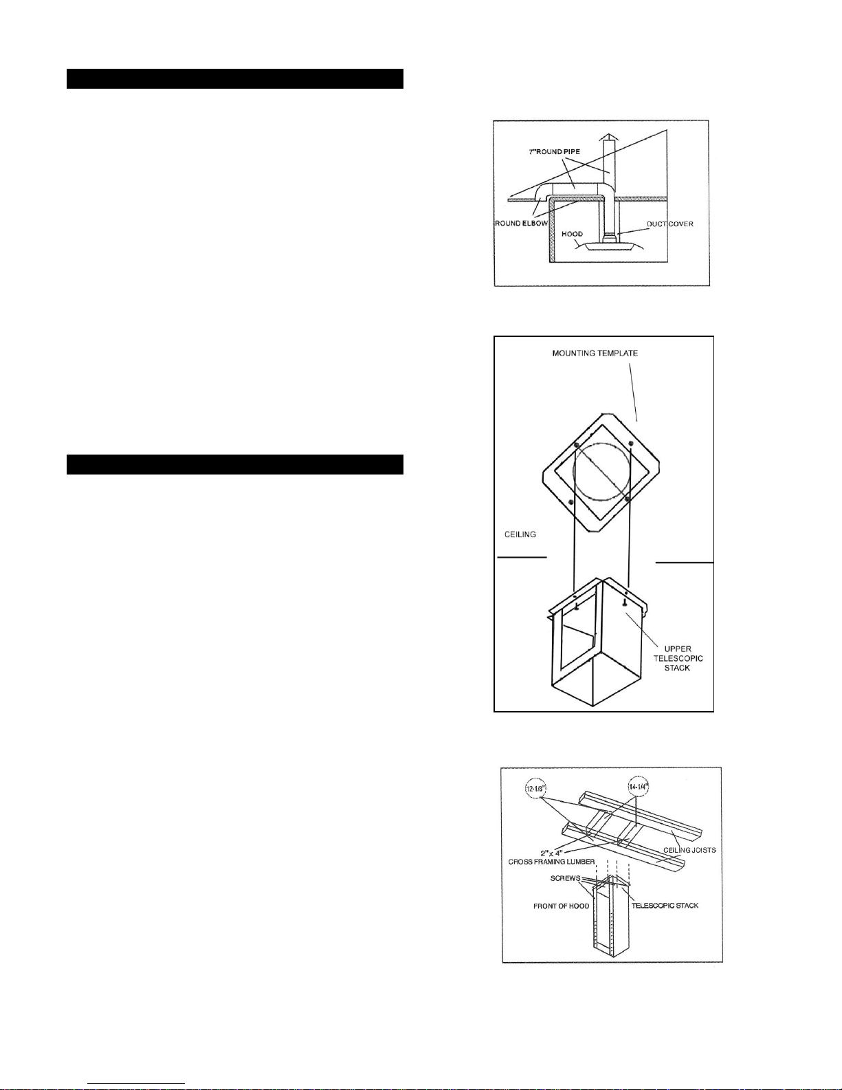
Decide the location of the venting pipe
from the hood to the outside (Figure 1).
A straight, short vent run will allow the hood
to perform more efficiently.
Try to avoid as many transitions, elbows,
and long runs as possible. Transitions,
elbows and/or long runs may reduce the
performance of the hood.
Temporarily wire the hood to test for proper
operation before installing.
Important: Peel protective film off the
hood and duct covers, if any.
Use duct tape to seal the joints between
pipe sections.
1. Mark centerlines of cook top or range on
ceiling. Use centerlines marked on ceiling
to position the mounting template as shown
in Figure 2.
2. Remove and save template. Cut and
remove ceiling drywall. Install 2” x 4” cross
framing lumber (not provided) between
ceiling joists.
3. The framing should be spaced 13-1/2” at
the front centerline and 11-1/8” on the sides.
Refer to Figure 3.
4. Finish the ceiling surface. Be sure to mark
the location of the ceiling joists and cross
framing lumber.
5. Align the mounting template to the ceiling
marks and tape in place with consideration
to ceiling joists and cross framing lumber
locations. Cut a 8-1/4” duct opening and
approximately a 1” wire access hole. Predrill holes for the 4 mounting screws as
indicated on the template.
Figure 1
Figure 2
Figure 3
7
Telescopic Stack Installation
Hood Installation
Wiring to Power Supply
6. Align the telescopic stack to the pre-drill
holes on the ceiling and fasten to the ceiling
with four mounting screws (not provided).
Make sure screws are driven into the ceiling
at the middle of joists and cross framing
lumber for maximum support and stability.
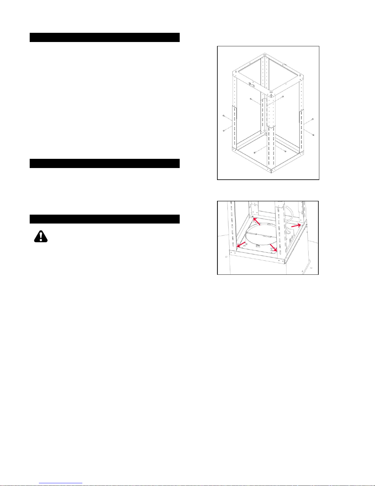
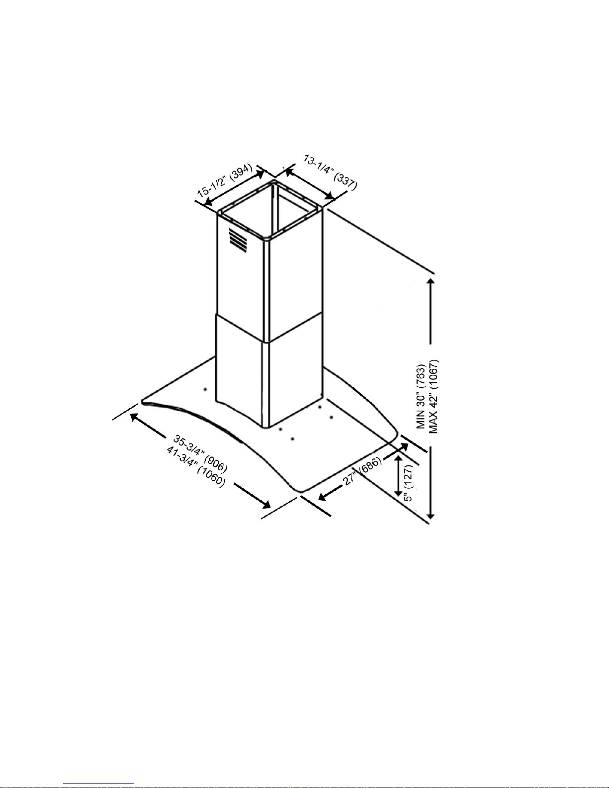
7. Adjust the telescopic stack using reference
F in Table 1 and measurement on Page 15.
Tighten from the side with 8 screws
(provided) as shown in Figure 4.
8. Slide the duct covers up the telescopic
stack, and temporary hold the duct covers
up.
9. Install the exhaust plate using 4 screws.
10. Align the hood with the telescopic stack and
lock the unit in place. Refer to Figure 5.
SAFETY WARNING
RISK OF ELECTRICAL SHOCK. THIS
RANGE HOOD MUST BE PROPERLY
GROUNDED. MAKE SURE THIS IS DONE
BY A QUALIFIED ELECTRICIAN IN
ACCORDANCE WITH ALL APPLICABLE
NATIONAL AND LOCAL ELECTRICAL
CODES. BEFORE CONNECTING WIRES,
SWITCH POWER OFF AT SERVICE PANEL
AND LOCK SERVICE PANEL TO PREVENT
POWER FROM BEING SWITCHED ON
ACCIDENTALLY.
11. Route house wiring into the ceiling as close
to the installation location as possible.
Allow additional length of wiring to drop
down from the ceiling to the electric box.
12. Connect the electrical wires according to
color (green to green, white to white, and
black to black) and cap with wire
connectors. Green wire must be grounded
to reduce risk of electric shock.
Figure 4
Figure 5
8

Ductwork Installation
Final Assembly
Duct Cover Installation
Use 8” round aluminum or steel pipe (not
provided) to connect the plastic
11. Slide the inner duct cover up and secure to
the top of the telescopic stack with two
screws (provided).
12. Slide the outer duct cover downward so that
it sits properly on the hood.
13. Install the Aluminum Filters.
14. Turn power ON in control panel. Check all
lights and fan operation.
15. Make sure to leave this manual for the
homeowner.
9
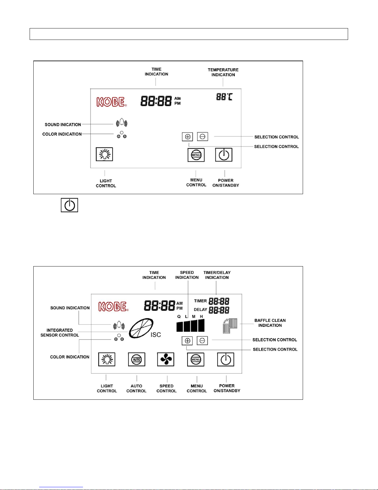
OPERATION INSTRUCTIONS
Figure 12
Figure 12
LCD DISPLAY (STANDBY MODE)
PRESS TO TURN ON/STANDBY THE LCD SCREEN
(When power is turned on, LCD screen will light up & remain lit. When power is pressed
again, LCD screen will remain lit for several seconds before going into STANDBY mode.)
LCD DISPLAY
Note: For best results, turn hood to QuietMode™ prior to preparation or cooking to
establish airflow in the kitchen. Adjust speed as needed.
10
GENERAL SETUP
NOTE: During selection mode, if a function is not chosen within 10 seconds, the icon will
stop flashing & selection mode will end. The settings below can only be performed
when the LCD screen is in STANDBY mode.
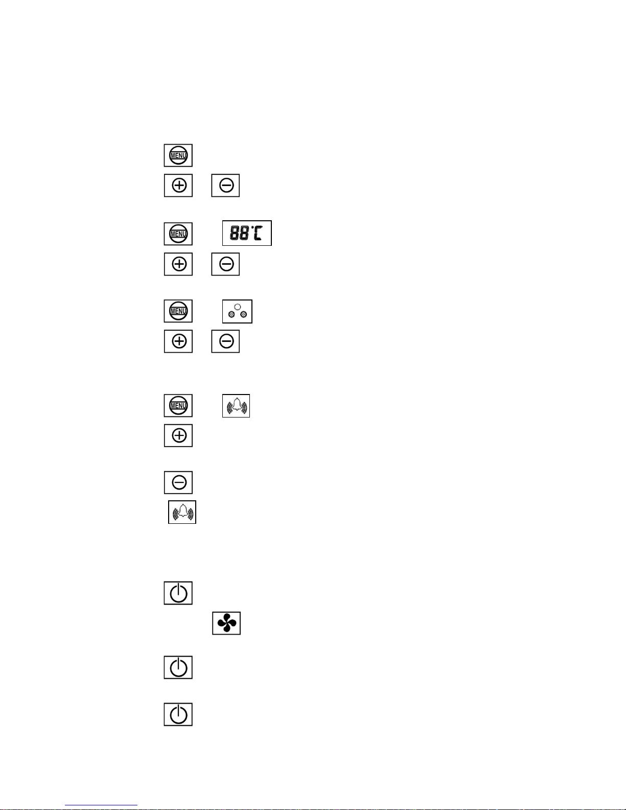
Setting Time
1. Press until time icon flashes.
2. Press or to select current time by hh:mm.
● Temperature Scale Setting
1. Press until icon flashes.
2. Press or to select Celsius or Fahrenheit.
Setting Background Color
1. Press until flashes.
2. Press or to select background color (purple, light blue, or green).
Setting Sound
1. Press until flashes.
2. Press to select sound.
OR
Press to mute sound.
(When appears, keypad sound is ON.)
HOOD OPERATION
Turning Fan ON/OFF
1. Press to turn panel ON.
(Each press of will cycle the fan through QuietMode™, Low, Medium, High,
and off.)
2. Press once will place fan on 3 minute delay shutoff.
OR
Press twice will immediately turn fan OFF.
11
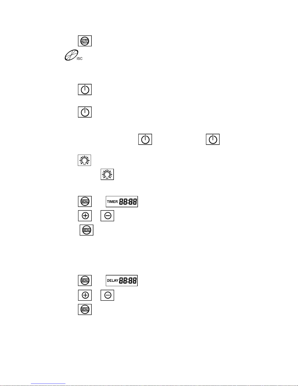
Turning ISC (Integrated Sensor Control) ON/OFF
1. Press to turn ISC ON.
( will indicate that the ISC system is ON. When gas, or higher than
normal room temperature is detected, fan will automatically turn ON. Fan will
turn to its highest speed and decrease speed until all gas and smoke are
eliminated.)
2. Press once will place ISC system on 3 minute delay shutoff.
OR
Press twice will immediately turn ISC system OFF.
Turning Lights ON
(Light control is separate from control. Pressing will not turn lights
on/off.)
1. Press to turn halogen lights ON.
(Each press of will cycle the light intensity through low, high, and off.)
Setting Timer Mode
1. Press until icon flashes.
2. Press or to set the desire time in the timer mode by mm:ss.
3. Press to start the timer mode.
(When countdown reaches 00:00, a warning sound will be emitted.)
Setting Delay Mode
(Delay Mode will turn off the fans or ISC feature. Other functions that are active will
not be turned off.)
1. Press until icon flashes.
2. Press or to set up the time for delay shut down by mm:ss.
3. Press to start delay shutdown.
(When countdown reaches 00:00, a warning sound will be emitted and fans or ISC
feature will turn off.)
12
MAINTENANCE
SAFETY WARNING
NEVER PUT YOUR HAND INTO AREA HOUSING THE FAN WHILE THE FAN IS
OPERATING.
Cleaning Hood Surface
CAUTION: NEVER USE ABRASIVE CLEANERS, PADS, OR CLOTHS. DO NOT
USE PAPER TOWEL ON STAINLESS STEEL.
For optimal operation, clean range hood and all baffle/spacer/filter/oil tunnel/oil container regularly.
*** Regular care will help preserve the appearance of the hood.
1. Use only mild soap or detergent solutions. Dry surfaces using soft cloth.
2. If hood looks splotchy (stainless steel hood), use a stainless steel cleaner to clean the surface
of the hood. Avoid getting cleaning solution onto or into the control panel. Follow directions of
the stainless steel cleaner. Caution: Do not leave on too long as this may cause damage to
hood finish. Use soft towel to wipe off the cleaning solution, gently rub off any stubborn spots.
Use dry soft towel to dry the hood.
3. DO NOT allow deposits to accumulate or remain on the hood.
4. DO NOT use ordinary steel wool or steel brushes. Small bits of steel may adhere to the surface
and cause rusting.
5. DO NOT allow salt solutions, disinfectants, bleaches, or cleaning compounds to remain in
contact with stainless steel for extended periods. Many of these compounds contain chemicals,
that may be harmful. Rinse with water after exposure and wipe dry with a clean lint free cloth.
To Clean or Replace Aluminum Mesh Filter
CAUTION: DRAIN OIL FROM ALUMINUM MESH FILTERS BEFORE OIL CAN
OVERFLOW.
1. The LCD display will indicate when aluminum mesh filter needs cleaning.
2. Remove all aluminum mesh filters.
3. Wash with warm soapy water. Dry completely before returning Filter.
13
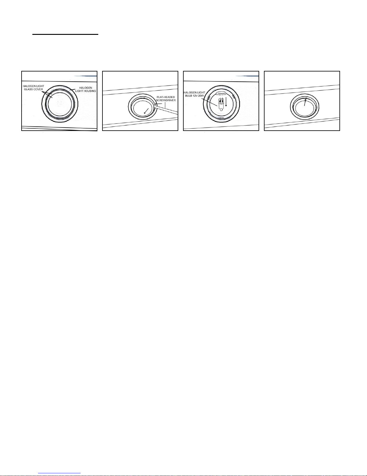
Replacing Light Bulb
CAUTION: HALOGEN LIGHT UNIT MAY BE HOT! WAIT UNTIL UNIT IS COOL.
1. Make sure all controls are off, and range hood is unplugged.
2. Place a flat-headed screwdriver into the groove between the halogen light glass covering and
the metal halogen light housing.
3. Pop out the halogen light glass covering.
4. Gently pull out the defective light bulb and discard.
5. Using a cloth, hold the new light bulb and push securely into light socket. Light bulb should be
12V 20W maximum.
6. Cover the halogen light housing with halogen light glass cover.
7. Turn range hood light ON to test for operation.
14

SPECIFICATIONS
MODEL / SIZE
IS2436GSF-1 / 36"
IS2442GSF-1 / 42”
COLOR
Commercial Grade Stainless Steel
CONSUMPTION / AMPERE
240W / 2.0A
VOLTAGE
120V 60Hz
NUMBER OF MOTORS
1
DESIGN
18-Gauge Seamless / Satin Finish
FAN TYPE
Double Horizontal Squirrel Cage
EXHAUST
Top 8” Round
CONTROLS
Touch Screen Multi Function LCD
HALOGEN LIGHTS
12V 20W x 2
OPTIONAL ACCESSORIES
(SOLD SEPARTELY)
Recirculating Kit – Item No. RD-0124-1
Net
Gross
WEIGHT (lbs)
(IS2436GSF-1)
95
124
(IS2442GSF-1)
101
131
SPEED
QuietMode
Low
Medium
High
Air Capacity (cfm)
250
460
560
700
Sone*
1.3*
3.5
5.0
6.0
Ceiling measurement is calculated with 30” minimum clearance height and 36” maximum clearance height.
Specifications subject to change without notice.
15
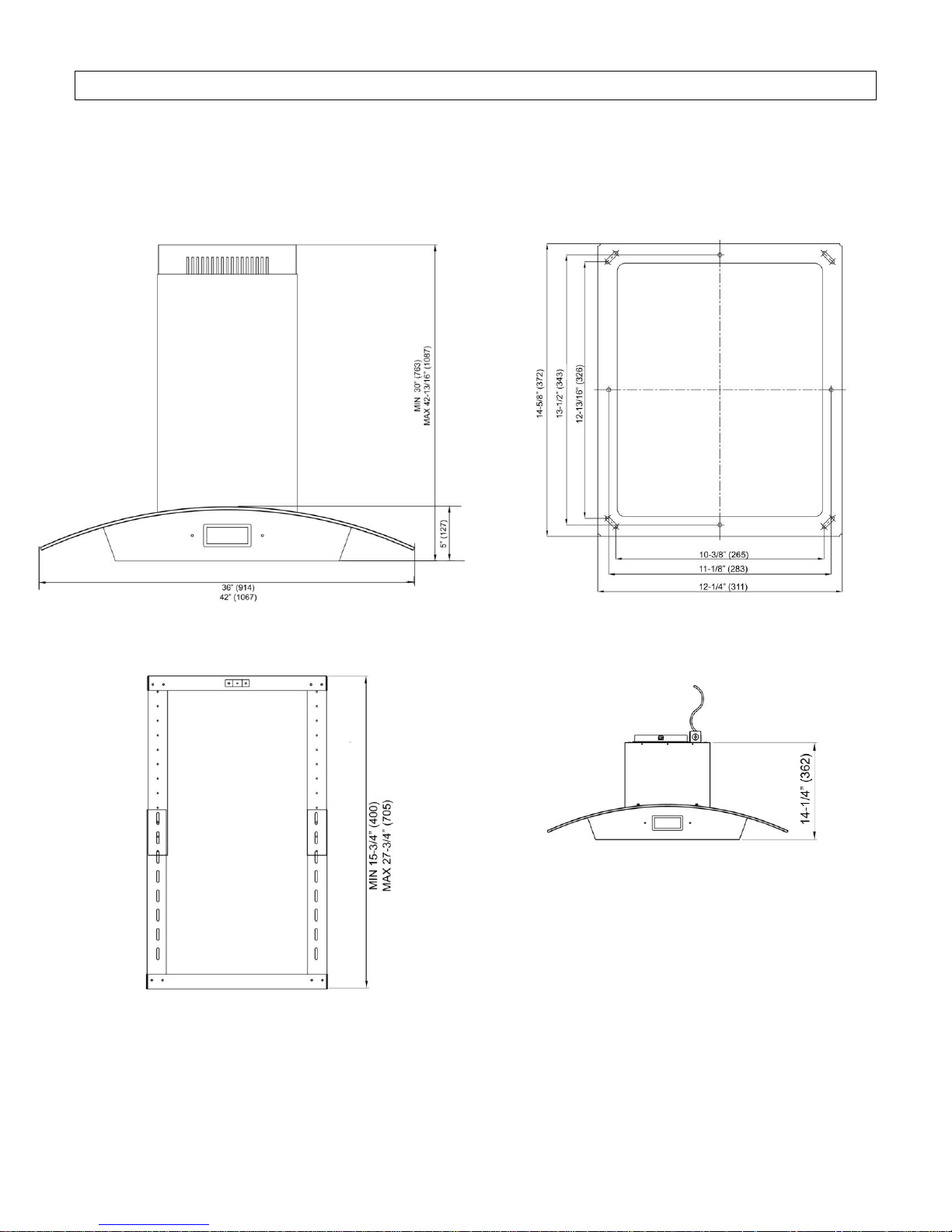
MEASUREMENTS & DIAGRAMS
All ( ) measurements are in millimeter.
All inch measurements are converted from millimeter. Inch measurements are estimated.
Mounting Template
Telescopic Stack Hood Body
16
17
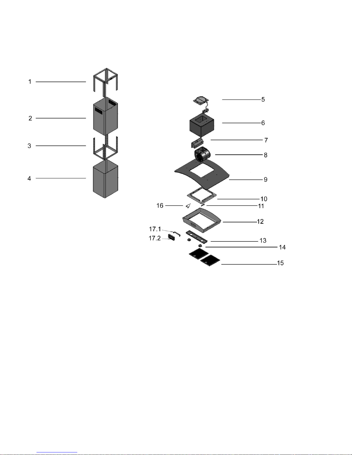
PARTS LIST
MODEL NO.:
IS2436GSF-1
IS2442GSF-1
MODEL NO. IS2436GSF-1
MODEL NO. IS2442GSF-1
NO.
DESCRIPTION
MODEL
PART NO.
1
Telescopic Stack
GP118207
2
Inner Duct Cover
GP118006
3
Telescopic Stack
GP054707-05
4
Outer Duct Cover
GP117906
5
Exhaust Plate
GP056004
6
Blower Frame
GP117807
7
Processor Board
LCD-002-1
8
Blower System
MT023
9
Glass Canopy
IS2436GSF-1
XP31135
IS2442GSF-1
XP31136
10
Housing Connector
GP118107
11
Sensor Bracket
GP054707-05
11
Hood Casing
GP117506
12
Light Panel
GP117606
13
Halogen Light Fixture
XP31422
14
Aluminum Filter
XP26707
16
ISC Sensor
ISC
17.1
LCD Panel Bracket
GP118507
17.2
LCD Panel
LCD-002-2
18
MODEL NO.:
IS2436GSF-1
IS2442GSF-1
19
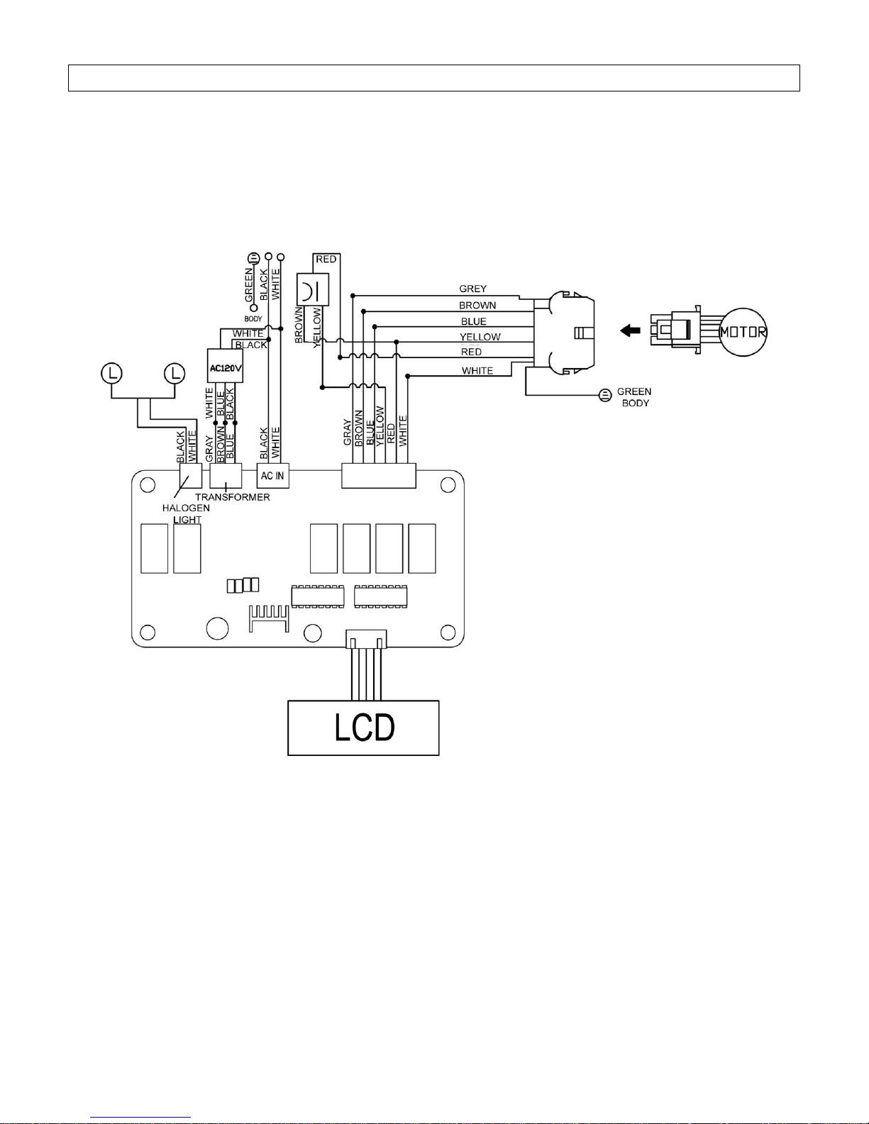
CIRCUIT DIAGRAM
MODEL NO.:
IS2436GSF-1
IS2442GSF-1
20
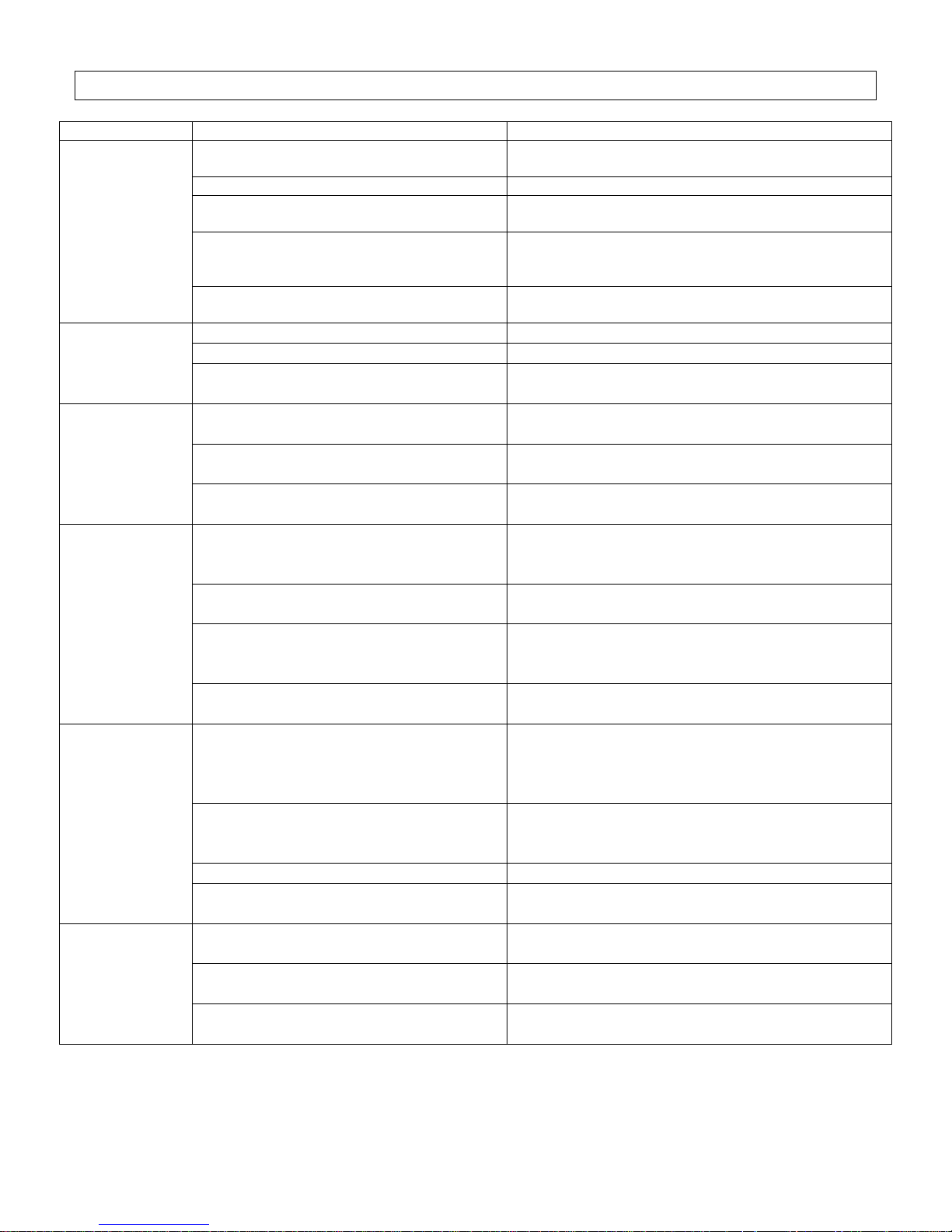
TROUBLE SHOOTING
Issue
Possible Cause
Solution
After Installation,
both motors and
lights are not
working.
The power is not on.
Make sure the circuit breaker and the unit’s power is
ON. Use a voltage meter to check the power supply.
The wire connection is not secure.
Check and tighten wire connection.
The control panel and processor board
wiring are disconnected.
Check wire continuity from control panel to processor
board.
The motor transformer is defective.
Check the power input and power output on the
motor transformer.
If it’s needed, replace the motor transformer.
The control panel and processor board is
defective.
Replace the control panel or processor board.
Lights are
working, but
motor(s) is not.
The motor(s) is defective.
Replace the motor.
The capacitor(s) is defective.
Replace capacitor(s).
The control panel or processor board is
defective.
Replace the control panel or processing board.
The range
hood is
vibrating.
The blower system is not secure.
Tighten the turbine impeller/squirrel cage and air
chamber.
The turbine impeller/squirrel cage is
not balanced.
Replace the turbine impeller/squirrel cage.
Hood is not secured in place.
Check the installation of hood, tighten the
mounting bracket.
The motor is
working, but
the lights are
not working.
Halogen Light bulb(s) is defective.
Try placing the trouble light bulb(s) to a working
socket, if the bulb(s) still doesn’t work; replace
the halogen light bulb(s).
The light wiring(s) is loose.
Check wire continuity from processor board to
light transformer to halogen light housing(s).
Light transformer is defective.
Check power input and power output on the light
transformer. If it’s needed, replace the light
transformer.
The control panel or processor board is
defective.
Replace the control panel or processing board.
The range
hood is not
venting out
correctly.
The range hood is installed outside of
the manufacture recommended
clearance.
Adjust the clearance between the range hoods
and cook top to 27” to 30”. For Island range
hood, the clearance between the range hoods
and cook top is 30” to 36”.
There is no make-up air inside the
house.
Open the window to enhance the performance
of the range hood by creating a sufficient makeup air.
Obstacle blocking the pipe work.
Remove all obstacles from the duct work.
The pipe size is smaller than the
suggested pipe size.
Change the ducting according to the
manufacture suggestion.
Cold air is
coming into the
home.
The pipe connection is not properly
sealed.
Check the pipe installation.
The damper is not properly installed or
is missing from the installation.
Check the damper installation.
The damper is not installed.
By installing the damper, it will help to eliminate
air backflow.
21

WARRANTY
WARRANTY CERTIFICATE
KOBE Range Hoods (referred to herein as “we”or “us”) warrants to the original purchaser
(referred to herein as “you” or “your”) all products manufactured or supplied by us to be free
from defect in workmanship and materials as follows:
TWO-YEAR LIMITED WARRANTY FOR PARTS AND LABOR ON KOBE PREMIUM
SERIES:
For two years from the date of your original invoice from a KOBE authorized dealer, we will, at
our sole discretion, choose to repair or replace the product free of charge that failed due to
manufacturing defects.
It is your sole responsibility to ensure the product is readily accessible for the service
technician to perform repairs. The service technician will not, under any circumstance,
remove, alter or modify any fixture built around and/or connected to the product to gain
access to perform repairs.
During the two-year Limited Warranty period, additional charges may apply which include but
are not limited to:
Service technician travel charges if the requested service location is 30-miles out of
KOBE’s authorized service area
Parts shipping expenses
Un-installation of defective product and Installation of replacement product
ONE-YEAR LIMITED WARRANTY FOR PARTS ON KOBE BRILLIA SERIES:
For one year from the date of your original invoice from a KOBE authorized dealer, we will
provide, free of charge, parts to replace those that failed due to manufacturing defects. It is our
sole discretion to choose to repair or replace defective parts. It is your sole responsibility for all
labor costs associated with this warranty.
Warranty Exclusions:
This warranty does not cover, including but not limited to the following:
a. Improper installation.
b. Any repair, alteration, modification not authorized by KOBE.
c. Duct alteration, modification and connection.
d. Incorrect electric current, voltage or wiring.
e. Normal maintenance and service required for the product.
f. Consumable parts such as light bulbs and carbon filters.
g. Improper usage of the product that it is not intended for, such as commercial use,
outdoor use and multi-family use.
h. Normal wear and tear.
i. Chips, scratches or dents by abuse or misuse of the product.
j. Damages caused by accident, fire, flood and other Acts of God.
k. Expenses incurred for service located outside of the designated service area.
l. Purchases from unauthorized dealers.
m. Removal fees of defective product and Installation fees associated with replacement
product.
22
 Loading...