

KOBE BRILLIA SERIES INX-026OVS-INX2630SQB-600-40, INX2630SQB-700-2 Installation Instructions And Operation Manual
KOBE Brand Range Hood
Model No.
OVS-
INX2630SQB-600-40
BRILLIA SERIES INX-026
INSTALLATION INSTRUCTIONS
AND OPERATION MANUAL

IMPORTANT
READ THIS
FIRST
READ BEFORE INSTALLATION
1. Carefully check all contents of packages;
2. Thoroughly inspect the unit for any cosmetic damages or
defects;
3. Test the unit before installation;
4. Have a certified contractor/electrician do the installation.
IF THERE IS ANY PROBLEM:
1. DO NOT INSTALL THE UNIT AND KEEP ALL ORIGINAL
PACKAGING MATERIAL.
2. Have your original proof of purchase and product serial
number ready.
3. Call 1-877-BUY-KOBE (289-5623); or e-mail to
info@koberangehoods.com to report the problem.
NO RETURN, NO REFUND, NO EXCHANGE IF:
1. PRODUCT HAS BEEN INSTALLED
2. KNOCK-OUT HOLES HAVE BEEN PUNCTURED
3. MISSING ORIGINAL PACKAGING MATERIAL AND/OR
PARTS

CONTENTS
[ENGLISH]
- READ AND SAVE THESE INSTRUCTIONS -
IMPORTANT SAFETY INSTRUCTIONS ........................................................................ 1
COMPONENTS OF PACKAGE ...................................................................................... 3
INSTALLATION ............................................................................................................... 4
OPERATING INSTRUCTIONS ....................................................................................... 9
MAINTENANCE ............................................................................................................ 13
SPECIFICATIONS ........................................................................................................ 14
MEASUREMENTS & DIAGRAMS................................................................................. 15
PARTS LIST .................................................................................................................. 17
CIRCUIT DIAGRAM ...................................................................................................... 19
TROUBLE SHOOTING ................................................................................................. 20
WARRANTY .................................................................................................................. 21
WARRANTY INFORMATION FORM ............................................................................ 23
- READ ALL INSTRUCTIONS CAREFULLY BEFORE STARTING -
A L L W I R ING MUST BE DONE BY A PROFESSIO N A L A N D I N
A C C O R D A N C E W I T H N A T I O N A L A N D L O C A L E L E C T R I C A L C O D E S

IMPORTANT SAFETY INSTRUCTIONS
- PLEASE READ THIS SECTION CAREFULLY BEFORE INSTALLATION -
WARNING
:
TO REDUCE THE RISK OF FIRE, ELECTRIC SHOCK OR PERSONAL INJURY,
OBSERVE THE FOLLOWING:
1) Installation and electrical wiring must be done by qualified professionals and in accordance with all
applicable codes and standards, including fire-rated construction.
2) When cutting or drilling into wall or ceiling, be careful not to damage electrical wiring or other hidden
utilities.
3) Ducted fans must be vented to the outside.
a) Before servicing or cleaning unit, open the light panel and SWITCH POWER OFF AT SERVICE
PANEL.
b) Clean all grease laden surfaces frequently. To reduce the risk of fire and to disperse air
properly, make sure to vent air outside. DO NOT vent exhaust air into wall spaces, attics, crawl
spaces or garages.
NOTE - This warranty is void without an authorized agent’s receipt or if unit is
damaged due to misuse, poor installation, improper use, mistreatment,
negligence or any other circumstances beyond the control of KOBE
RANGE HOODS authorized agents. Any repair carried out without the
supervision of KOBE RANGE HOODS authorized agents will
automatically void the warranty.
- KOBE RANGE HOODS will not be held responsible for any damages to
personal property or real estate or any bodily injuries whether caused
directly or indirectly by the range hood.
WARNING
: TO REDUCE THE RISK OF PERSONAL INJURY IN THE EVENT OF A RANGE
TOP GREASE FIRE:
1. Keep all fan, baffle/spacer/filter/oil tunnel/oil container and grease-laden surfaces clean. Grease
should not be allowed to accumulate on fan, baffle/spacer/filter/oil tunnel/oil container.
2. Always turn hood ON when cooking.
3. Use high settings on cooking range ONLY when necessary.
4. Do not leave cooking range unattended when cooking.
5. Always use cookware and utensils appropriate for the type and amount of food prepared.
6. Use this unit only in the manner intended by the manufacturer.
7. Before servicing, switch power off at service panel and lock service panel (if possible) to prevent
power from switching on accidentally.
8. Clean ventilating fan frequently.
1
What to Do In The Event Of a Range Top Grease Fire
• SMOTHER FLAMES with a tight fitting lid, cookie sheet, or metal tray, and then turn off the burner.
KEEP FLAMMABLE OR COMBUSTIBLE MATERIAL AWAY FROM FLAMES. If the flames do not
go out immediately, EVACUATE THE AREA AND CALL THE FIRE DEPARTMENT or 911.
• NEVER PICK UP A BURNING PAN – You May Get Burned.
• DO NOT USE WATER, including wet dishcloths or towels – a steam blast will result.
• Use an extinguisher ONLY if:
a) You have a Class A, B, C extinguisher and know how to operate it.
b) The fire is small and contained in the area where it started.
c) The fire department has been called.
d) You can fight the fire with your back to an exit.
What to Do If You Smell Gas
-
Extinguish any open flame.
-
Do not try to turn on the lights or any type of appliance.
-
Open all doors and windows to disperse the gas. If you still smell gas, call the Gas Company and
Fire Department right away.
CAUTION
1. For general ventilation use only. Do not use to exhaust hazardous or explosive materials and
vapors.
2. To reduce the risk of fire, use only metal ductwork. Sufficient air is needed for proper combustion
and exhausting of gases through the flue (chimney) to prevent back drafting.
3. Follow the heating equipment manufacturer’s guideline and safety standards such as those
published by the National Fire Protection Association (NFPA), and the American Society for
Heating, Refrigeration and Air Conditioning Engineers (ASHRAE), and code authorities.
4. Activating any switch on may cause ignition or an explosion.
5. Due to the size and weight of this hood, installation by 2 persons is recommended.
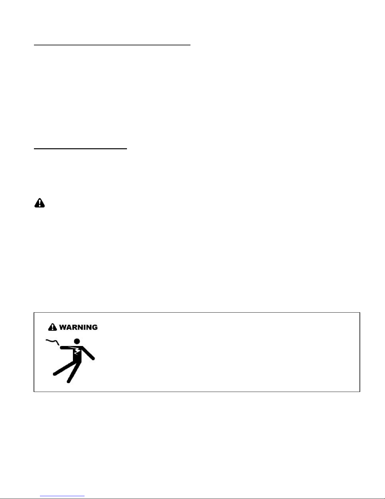
ELECTRICAL SHOCK HAZARD – Can result in serious injury or death.
Disconnect appliance from electric power before servicing. If equipped,
the fluorescent light bulb contains small amounts of mercury, which
must be recycled or disposed of according to Local, State, and Federal
Codes.
2
Adjustable
Liner (Sold Sepa
rately)
{J} Front Section of Liner
For the operation
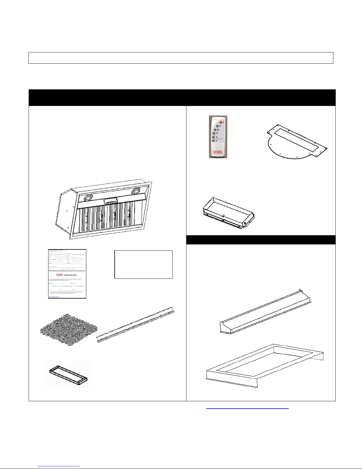
COMPONENTS OF PACKAGE
(Must keep all material for returns or refunds)
Range Hood Box
{A} BRILLIA Range Hood
{B} Warranty Registration Card
{C} Instruction Manual (WEBSITE)
{D} Baffle Filter X2
{E} Oil Tunnel
{F} Stainless Steel Spacer X2
{G} Remote Control with holder
{H} Rectangular Exhaust Plate
{I} Rectangular Exhaust Adapter
{A}
{B} {C}
manual, please refer to
our website:
KOBERangehoods.com
{D} {E}
{F}
-
FOR MORE INFORMATION, PLEASE VISIT OUR WEBSITE www.KOBERangeHoods.com OR CONTACT
KOBE RANGE HOODS AT (626) 775-8880.
{G} {H}
(AAA Batteries not included.)
{I}
{K} Rear Section of Liner
{J}
{K}
3
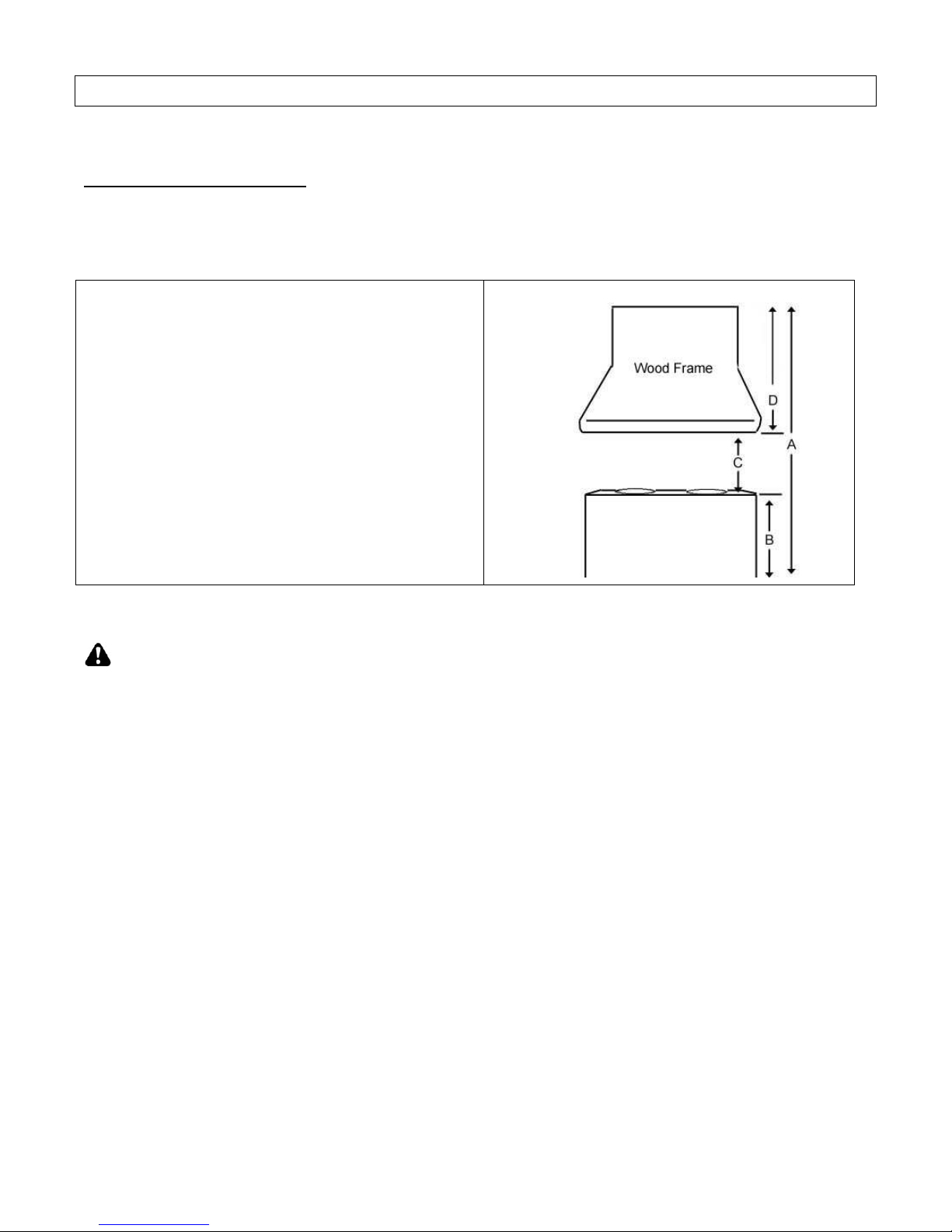
TABLE 1
INSTALLATION
PLEASE READ ENTIRE INSTRUCTIONS BEFORE PROCEEDING
Calculation before Installation
To calculate installation, please refer to TABLE 1. (All calculation in inches.)
- FOR UNDER THE CABINET -
A = Height of Floor to Ceiling
B = Height of Floor to Counter Top
(Standard: 36")
C = Height of Counter Top to Wood Frame Bottom
(Minimum 26" to 30")
D = Height of Wood Frame
SAFETY WARNING
HOOD MAY HAVE VERY SHARP EDGES; PLEASE WEAR PROTECTIVE GLOVES IF REMOVING
ANY PARTS FOR INSTALLING, CLEANING OR SERVICING.
NOTE: BE CAREFUL WHEN USING ELECTRICAL SCREWDRIVER, DAMAGE TO THE HOOD MAY
OCCUR.
4
on holes on the side of the insert are provided.
le.
Preparation Before Installation
NOTE: TO AVOID DAMAGE TO YOUR HOOD, PREVENT DEBRIS
FROM ENTERING THE VENT OPENING.
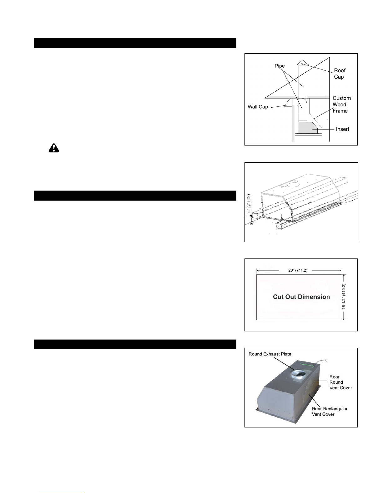
•
Decide the location of the venting pipe from the hood to the
outside. Refer to Figure 1.
•
A straight, short vent run will allow the hood to perform more
efficiently.
•
Try to avoid as many transitions, elbows, and long run as
possible. This may reduce the performance of the hood.
•
Temporarily wire the hood to test for proper operation before
installing.
•
Important: Peel protective film off the hood, if any.
•
Use duct tape to seal joints between pipe sections.
CAUTION
install the hood, turn off the power in an electric range at
the main electrical box. SHUT OFF THE GAS BEFORE
MOVING A GAS RANGE. And use a protective covering
to protect cooktop and/or countertop from damage.
: If moving the cooking range is necessary to
Custom Hood Preparation
1. The custom hood frame must be designed according to the
shape and the weight of the insert. Refer to Measurements
and Diagrams on Page 18-19.
2. A sturdy base (3/4 inch thick plywood recommended) is
needed to sustain the weight of insert.
3. If an optional liner will be installed, the side of the wood frame
must be sturdy (3/4 inch thick plywood recommended).
4. It is recommended to install front & rear stud support (not
included). Refer to Figure 2. For safety purposes, extra
installati
Prepare the side stud support if needed.
5. Determine and mark the centerlines on the base of the wood
frame where the insert will be installed.
6. Determine the proper location for the Power Supply Cab
Make a wiring access hole using a drill bit. Install the wire
cable and seal the gap around hole.
7. Cut out the opening where the insert will be installed. (Figure
3)
Liner Installation
8. The custom wood frame must have a sturdy base to
accommodate the cut-out for the insert. The base must be
recessed to accommodate the height of the liner (See liner
dimension on Page 19)
9. Secure the liner to the bottom of the base using screws (not
included) appropriate for the size and material of your wood
frame.
10. Liner is made up of two sections: a large, rear section with precut for insert and a front section for a total adjustable depth
between 23” and 25-3/4”.
11. Position the rear section of the liner so that it aligns with the
back edge of the custom wood frame. Use a pen to trace the
outline of the pre-cut area.
12. Install the rear section of the liner with 6 screws (not included).
13. Install the front section of the liner with 3 screws (not included)
(Additional Purchase required)
Figure 1
Figure 2
Figure 3
Figure 4
5
Hood Preparation Before Installation
CAUTION
install the hood, turn off the power in an electric range at
the main electrical box. SHUT OFF THE GAS BEFORE
MOVING A GAS RANGE.
14. Choose the required vent option. The Round Exhaust Plate is
pre-installed for top vent.
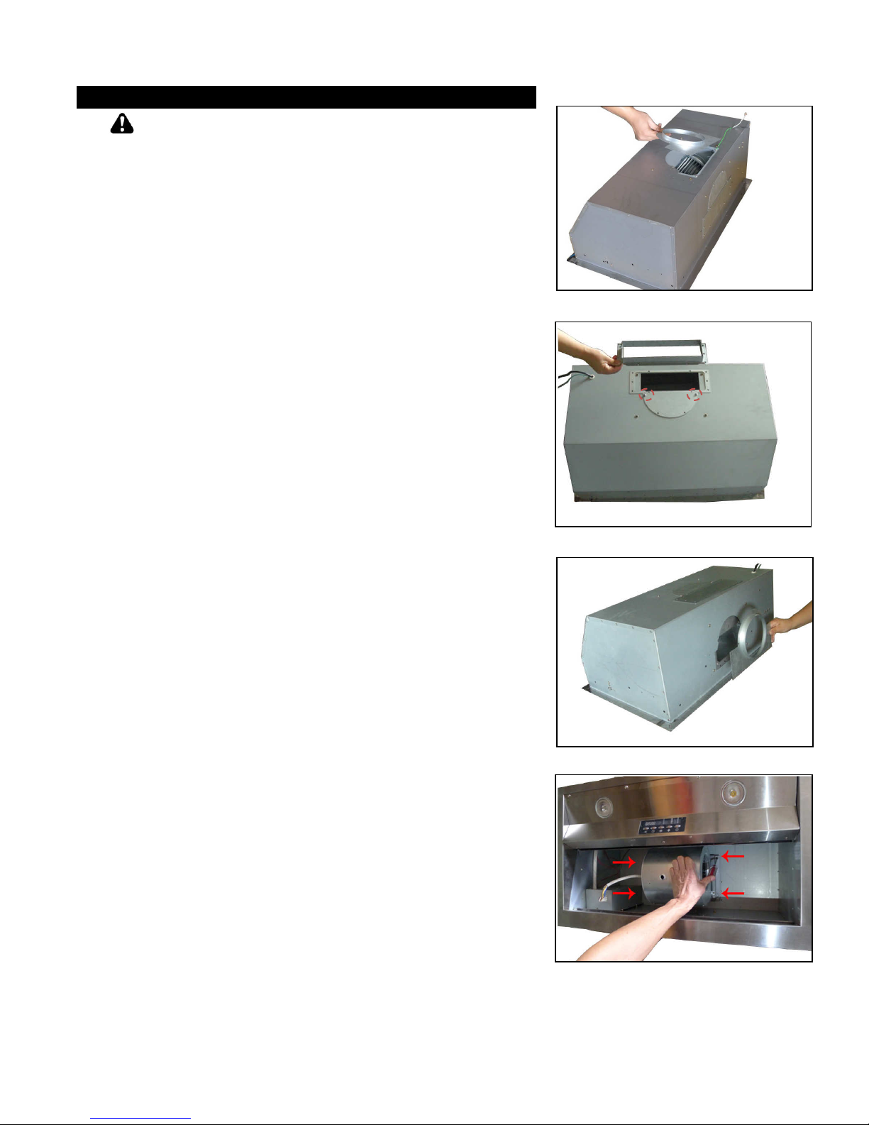
15. For Top 3-1/4” x 10” rectangular installation only:
-
Remove the pre-installed Round Exhaust Plate (Refer to
Figure 5). Keep screws to attach Rectangular Exhaust
Plate and Rectangular Exhaust Adapter.
-
Place Rectangular Exhaust Plate over vent and secure
with 2 screws (Refer to Figure 6). Place Rectangular
Exhaust Adapter over the Rectangular Exhaust plate and
secure with 10 screws (Refer to Figure 6).
-
Use remaining screws to secure exhaust plate.
For Rear Vent Options only:
NOTE: The blower is pre-installed for top vent. If
installing as rear vent, follow the steps below.
16. For Rear 6” round installation only:
-
Remove the Rear Round Vent Cover and Rear
Rectangular Vent Cover (Refer to Figure 4). Keep
screws to attach Round Exhaust Plate to rear vent.
-
Remove the pre-installed Round Exhaust Plate from top
vent (Refer to Figure 5). Attach it to the rear vent (Refer
to Figure 7) using the screws removed from vent covers.
-
Use the Round and Rectangular vent covers removed
from rear vent to seal top vent.
-
Remove the 4 screws that secure the blower system
(Refer to Figure 8). Hold the blower to keep it from
dropping as you remove screws. Keep screws to reattach blower. Slowly rotate blower system to align with
mounting holes at the back of the insert. Secure blower
using 4 screws (Refer to Figure 9).
17. For Rear 3-1/4” x 10” rectangular installation only:
-
Remove the Rear Round Vent Cover and Rear
Rectangular Vent Cover (Refer to Figure 4). Keep
screws to attach Rectangular Exhaust Plate and
Rectangular Exhaust Adapter.
-
Place the Rectangular Exhaust Plate over vent and
secure with 2 screws (Refer to Figure 10). Place
Rectangular Exhaust Adapter over the Rectangular
Exhaust Plate and secure with 10 screws (Refer to Figure
10).
-
Use remaining screws to secure exhaust plate.
-
Remove the pre-installed Round Exhaust Plate from top
vent and keep screws (Refer to Figure 4). Use the Round
and Rectangular vent covers removed from rear to seal
top vent.
-
Remove the 4 screws that secure the blower system
(Refer to Figure 8). Hold the blower to keep it from
dropping as you remove screws. Keep screws to reattach blower. Slowly rotate blower system to align with
mounting holes at the back of the insert. Secure the
blower using 4 screws (Refer to Figure 9).
: If moving the cooking range is necessary to
6
Figure 5
Figure 6
Figure 7
Figure 8
 Loading...