

Page 1

KOBE Brand Range Hood
Model No. / Nos de modèles / Modelo No. IN2730SF-1
IN-027 SERIES
INSTALLATION INSTRUCTIONS
INSTRUCCIONES DE INSTALACIÓN
AND OPERATION MANUAL
MANUEL D'INSTALLATION
ET MODE D'EMPLOI
Y MANUAL DE OPERACIÓN
Page 2

[ENGLISH] ...................................................................................................................... 2
[FRENCH] ..................................................................................................................... 25
[SPANISH] .................................................................................................................... 46
Page 3

NO RETURN, NO REFUND, NO EXCHANGE IF:
1. PRODUCT HAS BEEN INSTALLED
2. KNOCK-OUT HOLES HAVE BEEN PUNCTURED
3. MISSING ORIGINAL PACKAGING MATERIAL AND/OR
PARTS
IMPORTANT
READ THIS
FIRST
READ BEFORE INSTALLATION
1. Carefully check all contents of packages;
2. Thoroughly inspect the unit for any cosmetic damages or
defects;
3. Test the unit before installation;
4. Have a certified contractor/electrician do the installation.
IF THERE IS ANY PROBLEM:
1. DO NOT INSTALL THE UNIT AND KEEP ALL ORIGINAL
PACKAGING MATERIAL.
2. Have your original proof of purchase and product serial
number ready.
3. Call 1-877-BUY-KOBE (289-5623); or e-mail to
info@koberangehoods.com to report the problem.
1
Page 4

[ENGLISH]
- READ AND SAVE THESE INSTRUCTIONS -
CONTENTS
IMPORTANT SAFETY INSTRUCTIONS ................................ ................................ ................... 3
COMPONENTS OF PACKAGE ................................................................................................. 5
INSTALLATION ......................................................................................................................... 6
OPERATING INSTRUCTIONS ................................................................................................ 10
MAINTENANCE ...................................................................................................................... 11
SPECIFICATIONS ................................................................................................................... 13
MEASUREMENTS & DIAGRAMS ........................................................................................... 14
PARTS LIST ............................................................................................................................ 16
CIRCUIT DIAGRAM ................................................................................................................ 18
TROUBLE SHOOTING............................................................................................................ 19
WARRANTY ............................................................................................................................ 20
PRODUCT REGISTRATION ................................................................................................... 22
- READ ALL INSTRUCTIONS CAREFULLY BEFORE STARTING -
AL L W IR IN G MU S T BE D O N E B Y A P R O FE SS IO N A L A ND I N
AC CO RD AN C E W I T H NA TI O NA L A N D L OC AL E L EC T R I CA L CO DE S
2
Page 5
IMPORTANT SAFETY INSTRUCTIONS
NOTE
-
This warranty is invalid without an authorized agent’s receipt or if unit is
damaged due to misuse, poor installation, improper use, mistreatment,
negligence or any other circumstances beyond the control of KOBE
RANGE HOODS authorized agents. Any repair carried out without the
supervision of KOBE RANGE HOODS authorized agents will
automatically void the warranty.
- KOBE RANGE HOODS will not be held responsible for any damages to
personal property or real estate or any bodily injuries whether caused
directly or indirectly by the range hood.
- PLEASE READ THIS SECTION CAREFULLY BEFORE INSTALLATION -
WARNING: TO REDUCE THE RISK OF FIRE, ELECTRIC SHOCK OR PERSONAL
INJURY, OBSERVE THE FOLLOWING:
1) Installation and electrical wiring must be done by qualified professionals and in accordance with all
applicable codes and standards, including fire-rated construction.
2) When cutting or drilling into wall or ceiling, be careful not to damage electrical wiring or other hidden
utilities.
3) Ducted fans must be vented to the outside.
a) Before servicing or cleaning unit, open the light panel and SWITCH POWER OFF AT SERVICE
PANEL.
b) Clean all grease laden surfaces frequently. To reduce the risk of fire and to disperse air
properly, make sure to vent air outside. DO NOT vent exhaust air into wall spaces, attics, crawl
spaces or garages.
WARNING: TO REDUCE THE RISK OF PERSONAL INJURY IN THE EVENT OF A RANGE
TOP GREASE FIRE:
- Keep all fan, baffle/spacer/filter/oil tunnel/oil container and grease-laden surfaces clean. Grease
should not be allowed to accumulate on fan, baffle/spacer/filter/oil tunnel/oil container.
- Always turn hood ON when cooking.
- Use high settings on cooking range ONLY when necessary.
- Do not leave cooking range unattended when cooking.
- Always use cookware and utensils appropriate for the type and amount of food prepared.
- Use this unit only in the manner intended by the manufacturer.
- Before servicing, switch power off at service panel and lock service panel (if possible) to prevent
power from switching on accidentally.
- Clean ventilating fan frequently.
3
Page 6
What to Do In The Event Of a Range Top Grease Fire
ELECTRICAL SHOCK HAZARD – Can result in serious injury or
death. Disconnect appliance from electric power before servicing.
If equipped, the fluorescent light bulb contains small amounts of
mercury, which must be recycled or disposed of according to
Local, State, and Federal Codes.
• SMOTHER FLAMES with a tight fitting lid, cookie sheet, or metal tray, and then turn off the burner.
KEEP FLAMMABLE OR COMBUSTIBLE MATERIAL AWAY FROM FLAMES. If the flames do not
go out immediately, EVACUATE THE AREA AND CALL THE FIRE DEPARTMENT or 911.
• NEVER PICK UP A BURNING PAN – You May Get Burned.
• DO NOT USE WATER, including wet dishcloths or towels – a violent steam blast will result.
• Use an extinguisher ONLY if:
a) You have a Class A, B, C extinguisher and know how to operate it.
b) The fire is small and contained in the area where it started.
c) The fire department has been called.
d) You can fight the fire with your back to an exit.
What to Do If You Smell Gas
- Extinguish any open flame.
- Do not try to turn on the lights or any type of appliance.
- Open all doors and windows to disperse the gas. If you still smell gas, call the Gas Company and
Fire Department right away.
CAUTION
1. For general ventilation use only. Do not use to exhaust hazardous or explosive materials and
vapors.
2. To reduce the risk of fire, use only metal ductwork. Sufficient air is needed for proper combustion
and exhausting of gases through the flue (chimney) to prevent back drafting.
3. Follow the heating equipment manufacturer’s guideline and safety standards such as those
published by the National Fire Protection Association (NFPA), and the American Society for
Heating, Refrigeration and Air Conditioning Engineers (ASHRAE), and code authorities.
4. Activating any switch on may cause ignition or an explosion.
5. Due to the size and weight of this hood, two people installation is recommended.
4
Page 7

COMPONENTS OF PACKAGE
Range Hood Box
Liner (Sold Separately)
{A} KOBE Range Hood
{B} Warranty Registration Card
{C} Instruction Manual
{D} Aluminum Filter – 2
{E} Exhaust Plate – 1
{A}
{B} {C}
{D} {E}
{F} Liner
(Must keep all material for returns or refunds)
- FOR MORE INFORMATION, PLEASE VISIT OUR WEBSITE www.KOBERangeHoods.com OR
CONTACT KOBE RANGE HOODS AT (626) 775-8880.
5
Page 8
INSTALLATION
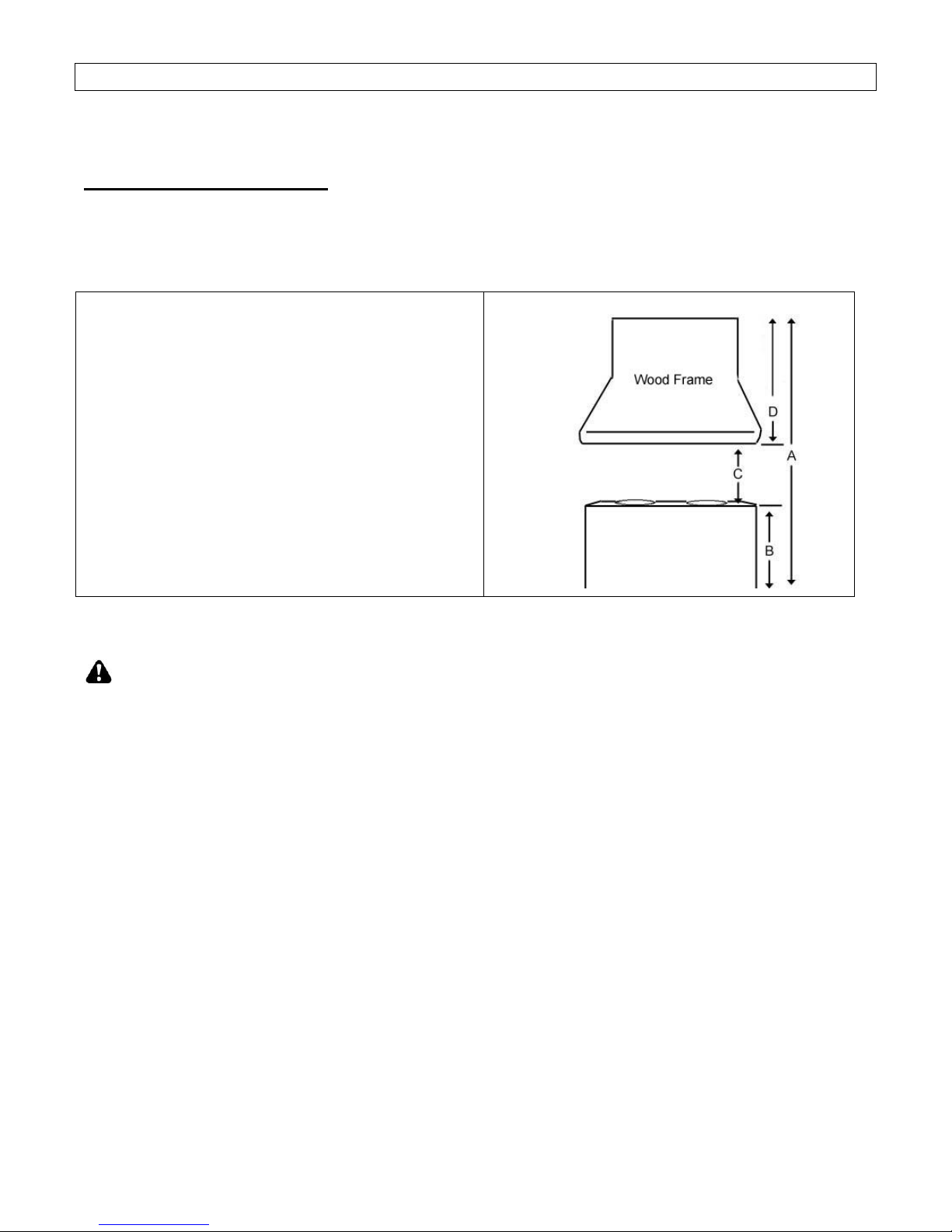
TABLE 1
A = Height of Floor to Ceiling
B = Height of Floor to Counter Top
(Standard: 36")
C = Height of Counter Top to Wood Frame
Bottom (Recommended 27" to 30")
D = Height of Wood Frame
PLEASE READ ENTIRE INSTRUCTIONS BEFORE PROCEEDING
Calculation before Installation
To calculate installation, please refer to TABLE 1. (All calculation in inches.)
- FOR UNDER THE CABINET -
SAFETY WARNING
HOOD MAY HAVE VERY SHARP EDGES; PLEASE WEAR PROTECTIVE GLOVES IF
REMOVING ANY PARTS FOR INSTALLING, CLEANING OR SERVICING.
NOTE: BE CAREFUL WHEN USING ELECTRICAL SCREWDRIVER, DAMAGE TO THE HOOD
MAY OCCUR.
6
Page 9

- For Insert installation -
Preparation Before Installation
NOTE: TO AVOID DAMAGE TO YOUR HOOD, PREVENT
DEBRIS FROM ENTERING THE VENT OPENING.
Decide the location of the venting pipe from the hood to
the outside. Refer to Figure 1.
A straight, short vent run will allow the hood to perform
more efficiently.
Try to avoid as many transitions, elbows, and long run
as possible. This may reduce the performance of the
hood.
Temporarily wire the hood to test for proper operation
before installing.
Important: Peel protective film off the hood, if any.
Use duct tape to seal joints between pipe sections.
CAUTION: If moving the cooking range is
necessary to install the hood, turn off the power in an
electric range at the main electrical box. SHUT OFF
THE GAS BEFORE MOVING A GAS RANGE. And use a
protective covering to protect cooktop and/or
countertop from damage.
Custom Hood Preparation
1. The custom hood frame must be sized to shape and the
weight of the insert. Refer to Measurements and
Diagrams on Page 13.
2. Install the Exhaust Plate using 4 screws. Refer to
Figure 2.
3. It must have a sturdy base (1/2 inch thick plywood
recommended) to sustain the weight of insert.
4. If an optional liner will be installed, the side of the wood
cabinet must be sturdy (1/2 inch thick plywood
recommended).
5. It is recommended to install a rear and front stud
support. Refer to Figure 3. The stud supports are
located 1-1/2” up from the base of the wood frame.
Liner Installation
6. The custom/wood hood must have a sturdy base to
accommodate the cut-out for the inset. The base must be
recessed to accommodate the height of the liner (See
liner dimension on Page 14)
7. Secure the liner to the bottom of the base using screws
(not included) appropriate for the size and material of your
wood frame.
8. Position the liner so that it aligns with the back edge of
the custom wood frame. Use a pen to trace the outline of
the pre-cut area. Remove the liner and proceed to Hood
Preparation Before Installation on Page 6.
9. Install the liner with 5 screws (not provided).
Figure 1
Figure 2
Figure 3
7
Page 10
Wiring to Power Supply
SAFETY WARNING
RISK OF ELECTRICAL SHOCK. THIS RANGE HOOD MUST
BE PROPERLY GROUNDED. MAKE SURE THIS IS DONE
BY QUALIFIED ELECTRICIAN IN ACCORDANCE WITH ALL
APPLICABLE NATIONAL AND LOCAL ELECTRICAL
CODES. BEFORE CONNECTING WIRES, SWITCH POWER
OFF AT SERVICE PANEL AND LOCK SERVICE PANEL TO
PREVENT POWER FROM BEING SWITCHED ON
ACCIDENTALLY.
10. Temporarily wire the hood to test for proper operation
before installing. If the insert does not operate, check
the circuit breaker or house fuse. If the insert is still not
working, disconnect the power supply and check the
continuity of all wiring connections.
11. Connect electrical wires.
12. Connect three wires (black, white and green) to house
wires and cap with wire connectors. Connect wires
according to their colors (i.e. black to black, white to
white, and green to green). See Figure 4.
13. Store wires in the wiring box.
Note: Connect all electrical wires before installing insert.
DO NOT turn on the power until installation is complete.
Duct Work Installation
14. Use 8” steel pipe (follow building codes in your area) to
connect the ducting on the hood to the ductwork above.
Use duct tape to seal and secure joints as shown in
Figure 5.
15. Please refer to local codes for the usage of the damper
(included). If necessary, remove the damper
mechanism and install as exhaust connector.
Hood Preparation Before Installation
CAUTION: If moving the cooking range is necessary
to install the hood, turn off the power in an electric range at
the main electrical box. SHUT OFF THE GAS BEFORE
MOVING A GAS RANGE.
16. Determine and mark the centerlines on the base of the
wood frame where the insert will be installed.
17. Determine and make all necessary cuts in the wall or
ceiling for the ductwork. Note: Install the duct work
before installing the insert.
18. Cut out the opening where the insert will be installed.
(Figure 6)
Figure 4
Figure 5
Figure 6
8
Page 11

Hood Installation
19. Release the screws located on each side of the insert.
Adjust the level of the hood casing support according to
the thickness of the base (1/2 thickness plywood
recommended). Tighten the screws to secure as shown
on Figure 7.
20. Install the insert inside the custom wood frame.
21. Make sure the hood casing support is secure before
releasing.
22. For a more secure installation, use the mounting holes
for the rear support which are located at 1-1/2” (38mm)
up from the insert base (screws not provided).
CAUTION: MAKE SURE HOOD IS SECURE BEFORE
RELEASING.
Final Assembly
23. Install Aluminum Filters. Insert the filters towards the
back of the unit and push up.
24. Make sure the Aluminum Filters are secure before
releasing.
Figure 7
9
Page 12
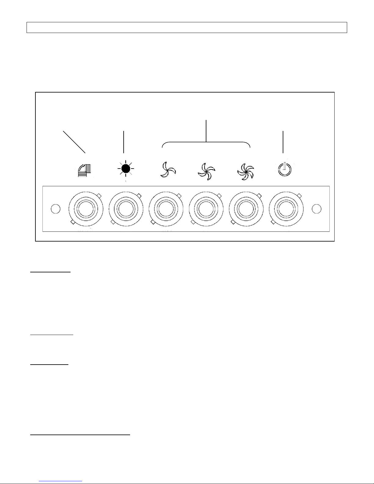
OPERATING INSTRUCTIONS
Change Filter
Indicator
Halogen Light
Control
Speed
Control
Power Control
This KOBE hood is equipped with five electronic push buttons with LED indicator, double powerful centrifugal
squirrel cage with aluminum filter, two bright 12-volt 20-watt halogen lights.
The five control buttons are Power Control (On/Off), Speed Control (High, Medium, & Low), and Light
Control. Refer to Figure 7.
Figure 7
Note: For best results, turn hood to Low prior to any preparation or cooking. Adjust speed as needed.
Power Control
Press Power Control to turn On/Off the hood.
This unit equipped with 3-minute delay shutoff. To activate this feature, press Power Control
button once, panel LED lights will flash and power will be completely shut off after 3 minutes.
Press Power Control button twice, the fans will be shut off immediately.
Speed Control
Press Speed Control to activate Low, Medium, & High Speed.
Light Control
(Light control is separate from ON/OFF control. Turning power off will not turn lights off.)
Press Light control to turn lights ON.
(Each press of Light Control will cycle the light intensity through high, low, and off.)
Aluminum Filter Change Indicator
10
Page 13

The indication under symbol will indicate when aluminum filter needs cleaning.
Remove to clean the aluminum filter.
(To purchase replacement filters, please contact your local KOBE dealer or call 626-775-8880)
MAINTENANCE
SAFETY WARNING
NEVER PUT YOUR HAND INTO AREA HOUSING THE FAN WHILE THE FAN IS
OPERATING.
Cleaning Hood Surface
CAUTION: NEVER USE ABRASIVE CLEANERS, PADS, OR CLOTHS. DO NOT USE
PAPER TOWEL ON STAINLESS STEEL.
For optimal operation, clean range hood and all baffle/spacer/filter/oil tunnel/oil container regularly.
*** Regular care will help preserve the appearance of the hood.
1. Use only mild soap or detergent solutions. Dry surfaces using soft cloth.
2. If hood looks splotchy (stainless steel hood), use a stainless steel cleaner to clean the surface of
the hood. Avoid getting cleaning solution onto or into the control panel. Follow directions of the
stainless steel cleaner. Caution: Do not leave on too long as this may cause damage to
hood finish. Use soft towel to wipe off the cleaning solution, gently rub off any stubborn spots.
Use dry soft towel to dry the hood.
3. DO NOT allow deposits to accumulate or remain on the hood.
4. DO NOT use ordinary steel wool or steel brushes. Small bits of steel may adhere to the surface
and cause rusting.
5. DO NOT allow salt solutions, disinfectants, bleaches, or cleaning compounds to remain in contact
with stainless steel for extended periods. Many of these compounds contain chemicals, which
may be harmful. Rinse with water after exposure and wipe dry with a clean lint free cloth.
To Clean Aluminum Filter
1. Remove all the aluminum filters.
2. Wash with warm soapy water. Dry thoroughly before returning into place.
11
Page 14
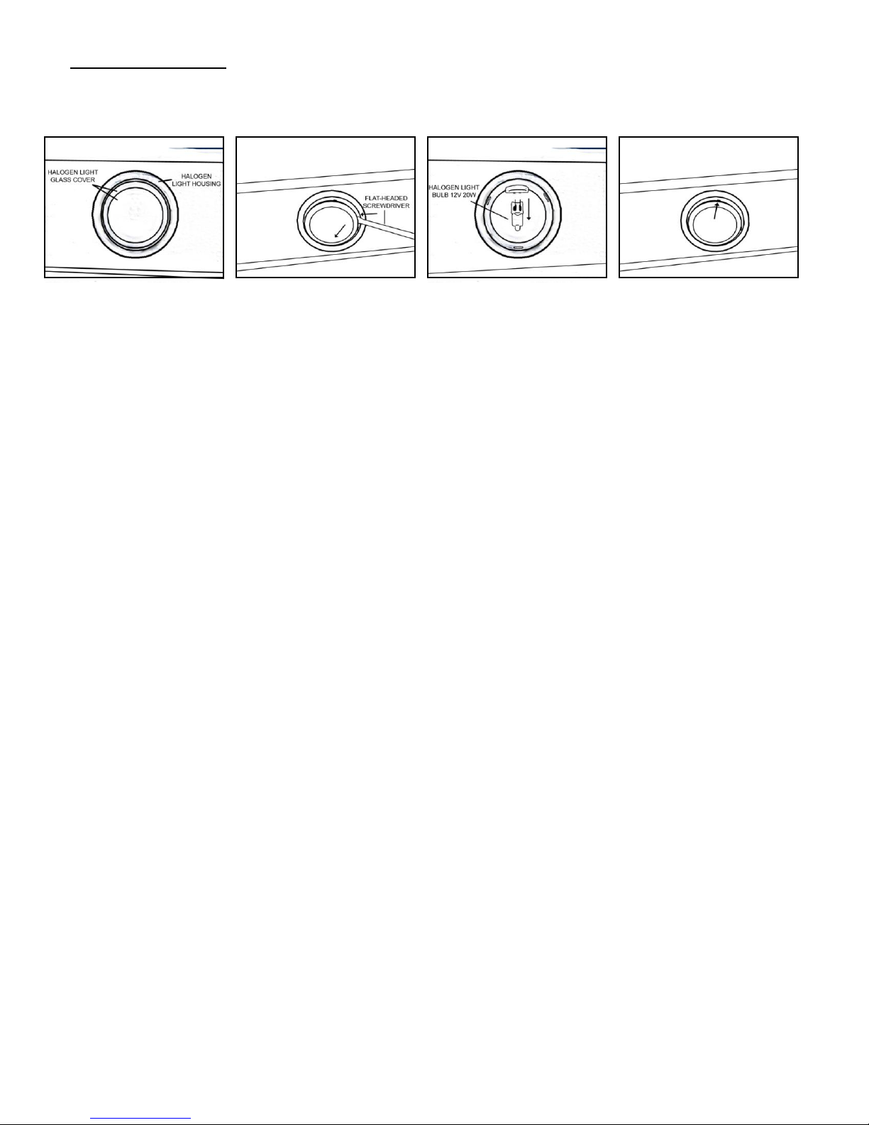
Replacing Light Bulb
CAUTION: HALOGEN LIGHT UNIT MAY BE HOT! WAIT UNTIL UNIT IS COOL.
1. Make sure all controls are off, and range hood is unplugged.
2. Place the flat-headed screwdriver into the groove of the halogen light glass covering and the
housing.
3. Pop out the halogen light glass covering.
4. Gently pull out the defective light bulb and discard. Light bulbs should be 12V 20W maximum.
5. Using a cloth, hold the new light bulb and push securely into light socket.
6. Return halogen light glass cover to the housing.
7. Turn range hood ON to test for operation.
12
Page 15

SPECIFICATIONS
MODEL / SIZE
IN2730SF-1
COLOR
18-Gauge Commercial Stainless Steel
CONSUMPTION / AMPERE
120W / 3.3A
VOLTAGE
120V 60Hz
NUMBER OF MOTORS
1
FAN TYPE: CENTRIFUGAL
Double Horizontal Squirrel Cage
EXHAUST
Top 8" Round w/ Damper
CONTROLS
5 Push-Button
- 3-Minute Delay Shutoff
HALOGEN LIGHTS
12V 20W Max. x 2
HOOD DIMENSION
(W X D X H)
27-1/2” x 11-3/8” x 9-3/4”
OPTIONAL ACCESSORIES
(W X D X H)
Liner: INL36211A (36” X 21” X 2”)
HOOD WEIGHT (lbs)
Net
Gross
IN2730SQB-1
24
32
Blower Air Capacity (cfm)
Low
Medium
High
350
400
700
Sone
3.0
4.0
5.5
dB
56
60
65
* One Sone is equivalent to 40 decibels.
**Specifications subject to change without notice.
13
Page 16
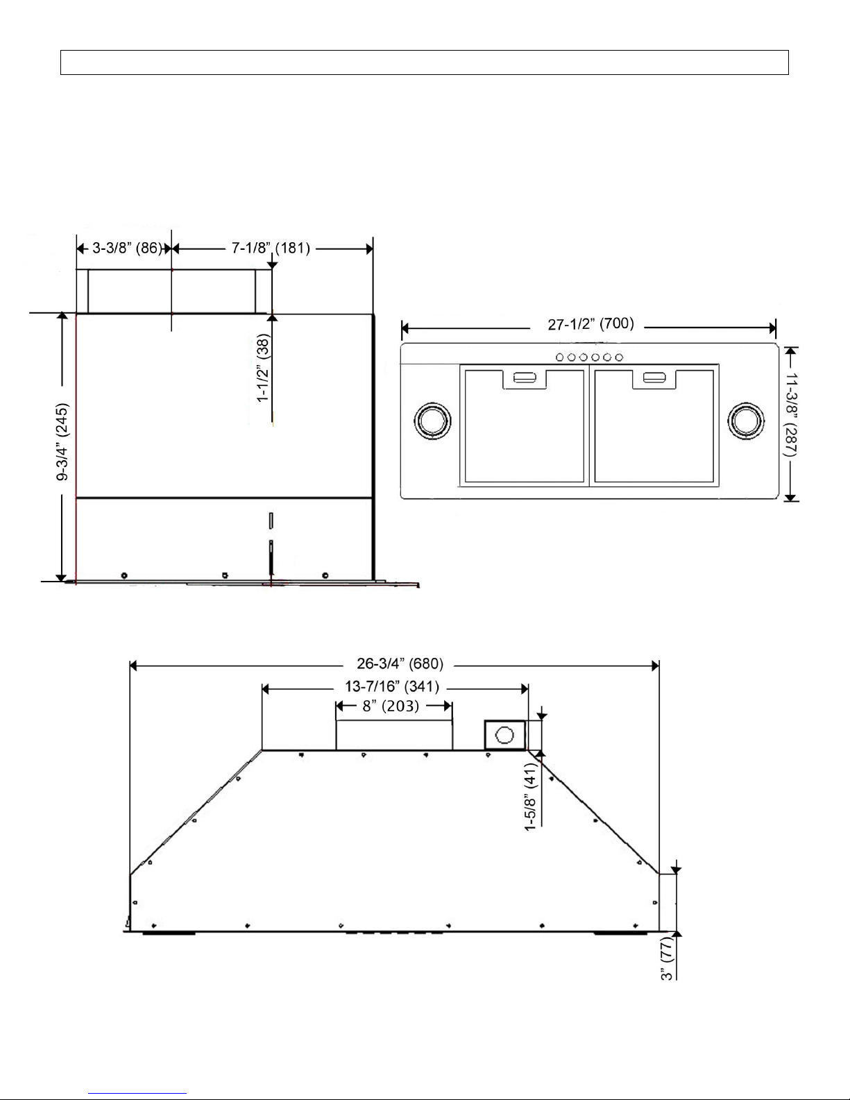
MEASUREMENTS & DIAGRAMS
All ( ) are in millimeter.
All inch measurements are converted from millimeters. Inch measurements are estimated.
MODEL NO: IN2730SF-1
Side View Bottom View
Front View
Stainless Steel Liner (Sold Separately)
14
Page 17
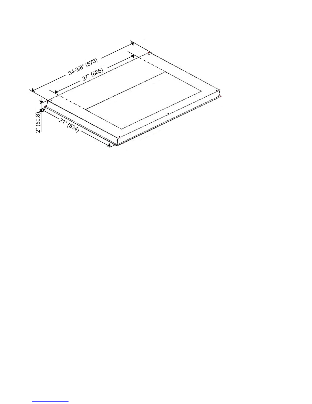
Model No. INL36211A
15
Page 18
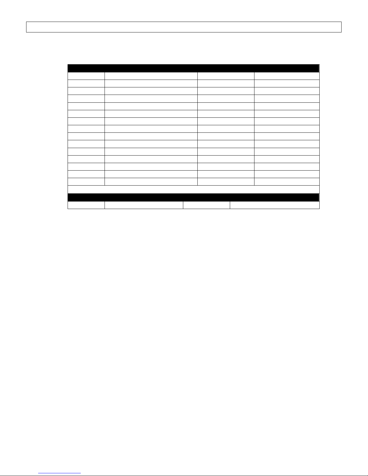
PARTS LIST
NO.
DESCRIPTION
MODEL/SIZE
PART NO.
1
Exhaust Plate
Q0229
2
Wiring Box
Q0119
3
Hood Casing
GP061507
4
Hood Casing Support
XP00173-6
5
Blower System
MT023
6
Electronic Support Panel
GP062307
7
Processor Board
XP31415
8
Light Transformer
XP31416
9
Capacitor (27 µf 250V)
XP22424
10
Halogen Light Housing
XP31422
11
Indicator Sensor
XP23003
12
Bottom Casing
GP061626
13
Control Unit Support Panel
GP061707
14
Control Unit
XP31414
15
Aluminum Filters
XP26717
Optional Liner
Model No.
16
Liner
INL36211A
IN2730-11-01
MODEL NO: IN2730SF-1
16
Page 19
Optional Liner (Sold Separately)
17
Page 20
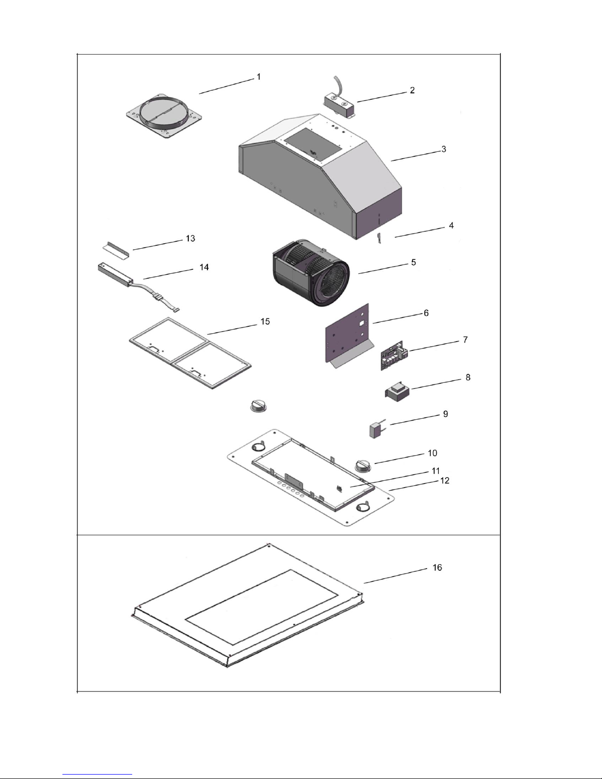
CIRCUIT DIAGRAM
MODEL NO.: IN2730SF-1
18
Page 21
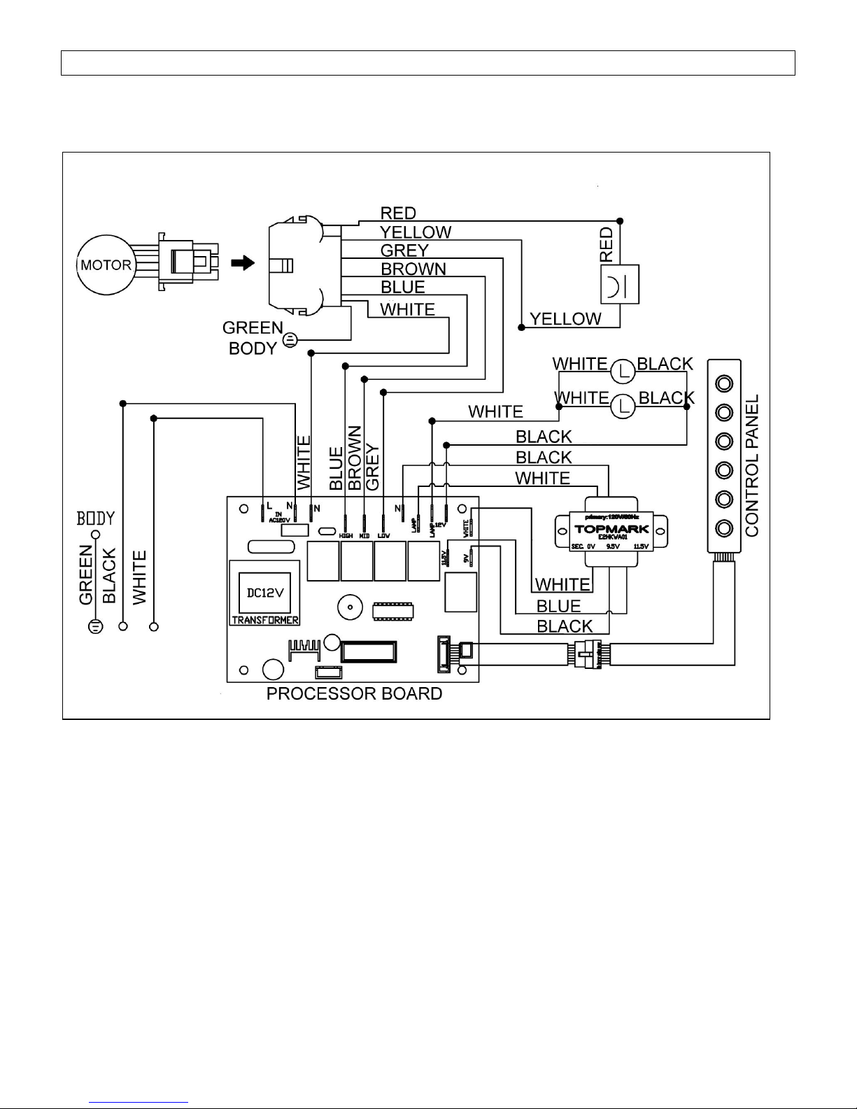
TROUBLE SHOOTING
Issue
Possible Cause
Solution
After Installation,
both motors and
lights are not
working.
The power is not on.
Make sure the circuit breaker and the unit’s power is
ON. Use a voltage meter to check the power supply.
The wire connection is not secure.
Check and tighten wire connection.
The control panel and processor board
wiring are disconnected.
Check wire continuity from control panel to processor
board.
The motor transformer is defective.
Check the power input and power output on the
motor transformer.
If it’s needed, replace the motor transformer.
The control panel and processor board is
defective.
Replace the control panel or processor board.
Lights are
working, but
motor(s) is not.
The motor(s) is defective.
Replace the motor.
The capacitor(s) is defective.
Replace capacitor(s).
The control panel or processor board is
defective.
Replace the control panel or processing board.
The range
hood is
vibrating.
The blower system is not secure.
Tighten the turbine impeller/squirrel cage and air
chamber.
The turbine impeller/squirrel cage is
not balanced.
Replace the turbine impeller/squirrel cage.
Hood is not secured in place.
Check the installation of hood, tighten the
mounting bracket.
The motor is
working, but
the lights are
not working.
Halogen Light bulb(s) is defective.
Try placing the trouble light bulb(s) to a working
socket, if the bulb(s) still doesn’t work; replace
the halogen light bulb(s).
The light wiring(s) is loose.
Check wire continuity from processor board to
light transformer to halogen light housing(s).
Light transformer is defective.
Check power input and power output on the light
transformer. If it’s needed, replace the light
transformer.
The control panel or processor board is
defective.
Replace the control panel or processing board.
The range
hood is not
venting out
correctly.
The range hood is installed outside of
the manufacture recommended
clearance.
Adjust the clearance between the range hoods
and cook top to 27” to 30”. For Island range
hood, the clearance between the range hoods
and cook top is 30” to 36”.
There is no make-up air inside the
house.
Open the window to enhance the performance
of the range hood by creating a sufficient makeup air.
Obstacle blocking the pipe work.
Remove all obstacles from the duct work.
The pipe size is smaller than the
suggested pipe size.
Change the ducting according to the
manufacture suggestion.
Cold air is
coming into the
home.
The pipe connection is not properly
sealed.
Check the pipe installation.
The damper is not properly installed or
is missing from the installation.
Check the damper installation.
The damper is not installed.
By installing the damper, it will help to eliminate
air backflow.
19
Page 22

WARRANTY
WARRANTY CERTIFICATE
KOBE Range Hoods (referred to herein as “we”or “us”) warrants to the original purchaser
(referred to herein as “you” or “your”) all products manufactured or supplied by us to be free from
defect in workmanship and materials as follows:
TWO-YEAR LIMITED WARRANTY FOR PARTS AND LABOR ON KOBE PREMIUM SERIES:
For two years from the date of your original invoice from a KOBE authorized dealer, we will, at
our sole discretion, choose to repair or replace the product free of charge that failed due to
manufacturing defects.
It is your sole responsibility to ensure the product is readily accessible for the service technician
to perform repairs. The service technician will not, under any circumstance, remove, alter
or modify any fixture built around and/or connected to the product to gain access to
perform repairs.
During the two-year Limited Warranty period, additional charges may apply which include but
are not limited to:
Service technician travel charges if the requested service location is 30-miles out of
KOBE’s authorized service area
Parts shipping expenses
Un-installation of defective product and Installation of replacement product
ONE-YEAR LIMITED WARRANTY FOR PARTS ON KOBE BRILLIA SERIES:
For one year from the date of your original invoice from a KOBE authorized dealer, we will
provide, free of charge, parts to replace those that failed due to manufacturing defects. It is our
sole discretion to choose to repair or replace defective parts. It is your sole responsibility for all
labor costs associated with this warranty.
Warranty Exclusions:
This warranty does not cover, including but not limited to the following:
a. Improper installation.
b. Any repair, alteration, modification not authorized by KOBE.
c. Duct alteration, modification and connection.
d. Incorrect electric current, voltage or wiring.
e. Normal maintenance and service required for the product.
f. Consumable parts such as light bulbs and carbon filters.
g. Improper usage of the product that it is not intended for, such as commercial use, outdoor
use and multi-family use.
h. Normal wear and tear.
i. Chips, scratches or dents by abuse or misuse of the product.
j. Damages caused by accident, fire, flood and other Acts of God.
k. Expenses incurred for service located outside of the designated service area.
l. Purchases from unauthorized dealers.
m. Removal fees of defective product and Installation fees associated with replacement
product.
20
Page 23

If we determine that the warranty exclusions listed above apply or if you fail to provide all
necessary documentation for warranty service, you will be responsible for all expenses
associated with the requested service, including parts, labor, shipping, travelling and any other
expense related to the service request.
To qualify for warranty service, you must:
1. Have the ORIGINAL proof of purchase
2. Be the ORIGINAL purchaser of the product
3. Have the model number
4. Have the serial number
5. Have a description of the nature of any defect in the product or part
TO REQUEST WARRANTY SERVICE, PLEASE CONTACT THE KOBE RANGE HOODS
SERVICE CENTER:
KOBE SERVICE CENTER
Tel: 1-855-800-KOBE (5623)
E-mail: kobe@adcoservice.com
21
Page 24

WARRANTY INFORMATION FORM
Fill in the blanks and keep this paper with the original invoice in a
safe place for future service purpose.
1. Date of purchase :
2. Model No. :
3. Serial No. :
For warranty service or spare parts purchase contact:
KOBE Service Center
Toll Free: 1-855-800-KOBE (5623)
Email: kobe@adcoservice.com
To report a problem, please contact:
Toll Free: 1-877-BUY-KOBE (289-5623)
Email: customer.service@koberangehoods.com
For product information contact:
Toll free: 1-877-BUY-KOBE (289-5623)
Email: info@koberangehoods.com
Your notes:
22
Page 25

[Français]
23
Page 26

PAS DE RETOUR, DE REMBOURSEMENT, NI
D’EXCHANGE SI:
1. Le produit a été installé
2. Les trous prédécoupés ont été perforés
3. Contenus et/ou pièces de l'emballage d'origine
manquent
IMPORTANT !
LISEZ CECI EN PREMIER
LIEU.
LISEZ CECI AVANT L'INSTALLATION
1. Vérifiez soigneusement tous les contenus des emballages;
2. Inspectez soigneusement l'appareil pour tous dommages ou
défauts cosmétiques;
3. Tester l'appareil avant l'installation;
4. Engagez un entrepreneur/électricien certifié pour procéder à
l'installation.
EN CAS DE PROBLEME:
1. N’INSTALLEZ PAS L'APPAREIL ET CONSERVER LE
CONTENU DE L 'EMBALLAGE D'ORIGINE.
2. Ayez votre preuve d'achat originale et le numéro de série du
produit.
3. Appelez au 1-877-BUY-KOBE (289-5623) ou contactez-nous par
courriel à info@koberangehoods.com pour signaler le problème.
24
Page 27

[FRENCH]
LIRE ET CONSERVER CES INSTRUCTIONS
TABLE DES MATIÈRES
CONSIGNES DE SÉCURITÉ IMPORTANTES ........................................................................... 26
CONTENU DE L’EMBALLAGE ................................ ................................................................ ... 28
INSTALLATION .......................................................................................................................... 29
MODE D’EMPLOI ....................................................................................................................... 33
ENTRETIEN PRÉVENTIF .......................................................................................................... 34
SPÉCIFICATIONS ...................................................................................................................... 36
MESURES ET SCHÉMAS .......................................................................................................... 37
LISTE DES PIÈCES ................................................................................................................... 39
SCHÉMA DE CÂBLAGE ............................................................................................................. 41
TROUBLE SHOOTING ............................................................................................................... 42
GARANTIE.................................................................................................................................. 43
ENREGISTREMENT DU PRODUIT ........................................................................................... 45
LIRE ATTENTIVEMENT TOUTES LES CONSIGNES AVANT DE COMMENCER
TOUT LE CÂBLAGE ÉLECTRIQUE DOIT ÊTRE EFFECTUÉ PAR UN PROFESSIONNEL EN
CONFORMITÉ AVEC LES CODES D’ÉLECTRICITÉ LOCAUX ET NATIONAUX.
25
Page 28

CONSIGNES DE SÉCURITÉ IMPORTANTES
- VEUILLEZ LIRE ATTENTIVEMENT CETTE SECTION AVANT L’INSTALLATION -
AVERTISSEMENT- AFIN DE RÉDUIRE LES RISQUES D'INCENDIE, DE CHOC
ÉLECTRIQUE ET DE BLESSURES, RESPECTEZ LES
CONSIGNES SUIVANTES :
1) L'installation et le câblage électrique doivent être effectués, par des techniciens qualifiés, en
conformité avec tous les codes et toutes les normes qui s'appliquent, même ceux relatifs aux
constructions ignifugées.
2) Lorsque vous découpez ou percez un mur ou un plafond, prendre soin de ne pas endommager le
filage électrique et autres conduits cachés.
3) Les hottes à évacuation doivent être évacuées à l’extérieur.
a. Avant une réparation, un entretien préventif ou un nettoyage, ouvrir le panneau d'éclairage et
COUPER LE COURANT ÉLECTRIQUE SUR LE PANNEAU DE SERVICE.
b. Nettoyer fréquemment toutes les surfaces chargées de graisse. Afin de réduire les risques
d’incendie et afin de disperser l’air adéquatement, évacuer l’air à l’extérieur. NE PAS ventiler l’air
d’évacuation dans les murs, les greniers, les vides sanitaires et les garages.
NOTE - La garantie de cet appareil sera nulle sans le reçu d'un distributeur autorisé de KOBE
RANGE HOODS ou si l'appareil est endommagé par une utilisation inadéquate, une
installation déficiente, un usage inapproprié, un mauvais traitement, de la négligence ou
par toute autre circonstance échappant au contrôle des distributeurs autorisés de KOBE
RANGE HOODS. Toute réparation non effectuée sous la supervision d'un agent autorisé
de KOBE RANGE HOODS annulera automatiquement la garantie.
- KOBE RANGE HOODS se dégage de toute responsabilité face à des dommages à la
propriété personnelle ou aux biens immeubles ou encore à des blessures corporelles
causées directement ou indirectement par la hotte de cuisinière.
AVERTISSEMENT- AFIN DE RÉDUIRE LES RISQUES DE BLESSURES
CORPORELLES DANS L'ÉVENTUALITÉ D'UN INCENDIE
DE GRAISSE SE DÉCLARANT SOUS LA HOTTE DE
CUISINIÈRE :
- Tenir le ventilateur, déflecteur/entretoise/filtre/récupérateur de graisse/récipient à graisse et les
surfaces chargées de graisse toujours propres. Les accumulations de graisse ne devraient pas
être tolérées sur un ventilateur, déflecteur/entretoise/filtre/récupérateur de graisse/récipient à
graisse.
- Toujours faire fonctionner la hotte lors de la cuisson.
- Utiliser les températures élevées de la cuisinière UNIQUEMENT lorsque nécessaire.
- Ne pas laisser la cuisinière sans surveillance lors d’une cuisson.
- Toujours utiliser les articles de cuisson et les ustensiles appropriés au type et à la quantité
d'aliments préparés.
- Utiliser l'appareil uniquement pour l'usage auquel le fabricant l'a destiné.
- Avant l'entretien courant, couper l'alimentation électrique au panneau de service et verrouiller ce
dernier (si possible) pour éviter une mise en marche accidentelle.
- Nettoyer fréquemment le ventilateur.
26
Page 29

RISQUE DE CHOC ÉLECTRIQUE - Pouvant entraîner la
mort ou des blessures graves. Couper l'alimentation
électrique à l'appareil avant tout entretien ou toute
réparation. Si la hotte est munie d'une ampoule
fluorescente, cette dernière contient une petite quantité
de mercure et, en conséquence, elle doit être recyclée ou
éliminée conformément aux codes locaux, provinciaux et
fédéraux qui s'appliquent
Que faire en cas d'un incendie de graisse sur la cuisinière?
ÉTOUFFER LES FLAMMES à l'aide d'un couvercle hermétique, une plaque à biscuits ou un
plateau en métal, puis fermer le rond ou le brûleur. GARDER LES MATÉRIAUX INFLAMMABLES
OU COMBUSTIBLES LOIN DES FLAMMES. Si les flammes ne s'éteignent pas immédiatement,
ÉVACUER LA ZONE ET APPELER LE SERVICE D'INCENDIE ou le 911.
NE JAMAIS SOULEVER UNE CASSEROLE EN FEU - Il y a risque de brûlure.
NE PAS UTILISER D'EAU y compris serviettes ou linges à vaisselle mouillés - cela provoquerait un
violent jet de vapeur.
Utiliser un extincteur SEULEMENT si :
a) vous possédez un extincteur de classe A, B ou C et savez vous en servir;
b) le feu est petit et est contenu dans la zone de départ;
c) vous avez appelé le service d'incendie;
d) vous pouvez combattre le feu le dos près d'une sortie.
Que faire si une odeur de gaz se dégage?
- Éteindre toute flamme nue.
- Ne pas essayer d'allumer des lumières ou tout type d'appareil électroménager.
- Ouvrir toutes les portes et fenêtres afin de chasser le gaz. Si une odeur de gaz est toujours
perceptible, appeler immédiatement votre fournisseur de gaz ainsi que le service d'incendie.
ATTENTION
1) Cette hotte doit être utilisée uniquement pour une ventilation normale. Ne pas s'en servir pour
évacuer des substances et vapeurs dangereuses ou explosives.
2) Afin de réduire les risques d'incendie, employer seulement des conduits de métal. Il doit y avoir
suffisamment d’air pour une combustion et une évacuation des gaz appropriées par le conduit de
fumée (cheminée) afin d’éviter le refoulement d’air.
3) Suivre les directives et les consignes de sécurité des fabricants d'équipement de chauffage comme
celles publiées par le National Fire Protection Association (NFPA) et l'American Society for
Heating, Refrigeration and Air Conditioning Engineers (ASHRAE) de même que les codes en vigueur.
4) L’activation de tout interrupteur peut provoquer l’allumage ou une explosion.
5) En raison de la taille et du poids de la hotte, il est recommandé que deux personnes participent à
l’installation.
27
Page 30

CONTENU DE L’EMBALLAGE
Boîte de la hotte de cuisinière
Revêtement (vendu séparément)
{A} Hotte de cuisinière KOBE
{B} Certificat de garantie
{C} Notice d’installation et mode d’emploi
{D} Filtres en aluminium – 2
{E} Plaque en plastique – 1
{A}
{B} {C}
{D} {E}
{F} Revêtement
(Pour tout retour ou remboursement, conserver tout le matériel ainsi que l’emballage d'origine)
POUR DE PLUS AMPLES RENSEIGNEMENTS, VEUILLEZ VISITER NOTRE SITE WEB
www.KOBERangeHoods.com OU COMMUNIQUER AVEC KOBE RANGE HOODS AU (626) 775-8880.
28
Page 31

INSTALLATION
TABLEAU 1
A. = Hauteur entre le plancher et le plafond
B. = Hauteur entre le plancher et le plan de travail
(hauteur standard : 36 po)
C. = Hauteur désirée entre le plan de travail et
le dessous de la hotte(dégagement
recommandé : de 27 po à 30 po)
D. = Hauteur du cadre en bois
VEUILLEZ LIRE LES INSTRUCTIONS AU COMPLET AVANT L’INSTALLATION
Prise de mesures avant l’installation
Pour calculer les mesures, veuillez vous référer au TABLEAU 1. (Toutes les mesures sont données en
pouces).
- HOTTE INSTALLÉE SOUS UNE ARMOIRE -
CONSIGNES DE SÉCURITÉ
LES HOTTES PEUVENT AVOIR DES BORDS TRÈS TRANCHANTS; VEUILLEZ PORTER
DES GANTS DE PROTECTION, SI NÉCESSAIRE, POUR RETIRER DES PIÈCES LORS DE
L'INSTALLATION, DU NETTOYAGE, DE L'ENTRETIEN ET DES RÉPARATIONS.
NOTE : FAIRE PREUVE DE PRÉCAUTION EN UTILISANT UN TOURNEVIS ÉLECTRIQUE
PUISQUE CE DERNIER RISQUE D'ENDOMMAGER LA HOTTE.
29
Page 32

– Installation de l’insert –
Préparation avant l’installation
Préparation de la hotte sur mesure
Installation du revêtement
Photo 1
Photo 3
Photo 2
NOTE : AFIN DE PRÉVENIR TOUT DOMMAGE À LA
HOTTE, IL FAUT EMPÊCHER LES DÉBRIS DE
PÉNÉTRER DANS L'OUVERTURE DE VENTILATION.
Choisir l’emplacement du conduit de ventilation de la
hotte à l’extérieur. Voir la Photo 1.
Un conduit court et droit permet de maximiser le
rendement de la hotte.
Essayer d'éviter autant que possible les raccords, les
coudes et les longues sections de conduit, puisque
ceux-ci peuvent réduire le rendement de la hotte.
Avant de l'installer, brancher temporairement la hotte
pour vérifier si son fonctionnement est adéquat.
Important : Enlever la pellicule protectrice de la
hotte, s’il y a lieu.
Utiliser du ruban adhésif entoilé pour sceller les
raccords entre les sections de tuyau.
AVERTISSEMENT : S'il faut déplacer la
cuisinière électrique pour installer la hotte, couper
d'abord l'alimentation électrique à cette cuisinière par le
panneau de service. COUPER LE GAZ AVANT DE
DÉPLACER UNE CUISINIÈRE À GAZ. Utiliser également
un revêtement protecteur pour protéger la surface de
cuisson et/ou le revêtement de comptoir.
1. Le cadre sur mesure pour la hotte doit être dimensionné
selon la taille et le poids de l’insert. Voir les mesures et
schémas à la page 35.
2. Installer la plaque en plastique à l’aide de 4 vis. Voir la
Photo 2.
3. La base doit être robuste (contreplaqué d’une épaisseur
de ½ pouce) pour soutenir le poids de l’insert.
4. Si un revêtement supplémentaire est installé, les côtés du
cadre en bois doivent être robustes (contreplaqué d’une
épaisseur de ½ pouce recommandé).
5. Il est recommandé d’installer des poteaux de support
arrière et avant. Voir la Figure 3. Les poteaux de support
arrière et avant sont installés à 1-½ po au-dessus de la
base du cadre en bois.
6. La base du cadre en bois sur mesure doit être robuste
afin de tenir compte du découpage pour l’insert. La base
doit être encastrée tout en considérant la hauteur du
revêtement (Voir les dimensions du revêtement à la page
36).
7. Fixer solidement le revêtement au bas de la base à l’aide
des vis (non comprises) appropriées à la taille et
matériaux de votre cadre en bois.
30
Page 33

8. Positionner la section arrière du revêtement afin qu’elle
Branchement à l’alimentation électrique
Installation du système de conduits
Photo 5
Photo 4
soit alignée au dos du cadre en bois sur mesure. Utiliser
un stylo pour tracer les lignes de la section prédécoupée.
Retirer le revêtement et poursuivre à la « Préparation de
la hotte avant l’installation » à la page 28.
9. Installer le revêtement à l’aide de 5 vis (non comprises).
CONSIGNES DE SÉCURITÉ
RISQUE DE CHOC ÉLECTRIQUE. CETTE HOTTE DE
CUISINIÈRE DOIT ÊTRE MISE À LA TERRE
ADÉQUATEMENT. CE TRAVAIL DOIT ÊTRE EXÉCUTÉ
PAR UN ÉLECTRICIEN PROFESSIONNEL EN
CONFORMITÉ AVEC TOUS LES CODES D’ÉLECTRICITÉ
LOCAUX ET NATIONAUX QUI S’APPLIQUENT. AVANT DE
BRANCHER LES FILS, COUPER LE COURANT
ÉLECTRIQUE AU PANNEAU DE SERVICE ET
VERROUILLER CE DERNIER POUR ÉVITER QUE LE
COURANT SOIT REMIS ACCIDENTELLEMENT
10. Avant l’installation, raccorder temporairement la hotte
pour vérifier son bon fonctionnement. Si l’insert ne
fonctionne pas, vérifier les disjoncteurs ou les fusibles de
la maison. Si l’insert ne fonctionne toujours pas,
débrancher la source électrique et vérifier la continuité de
toutes les connexions de câblage.
11. Raccorder les fils électriques.
12. Raccorder les trois fils (noir, blanc et vert) aux fils de la
maison et couvrez-les avec des capuchons de connexion.
Raccorder les fils selon la couleur (c.-à-d. noir avec noir,
blanc avec blanc et vert avec vert). Voir la Photo 4.
13. Ranger les fils dans le boîtier de câblage.
Note : Raccorder tous les fils électriques avant d’installer
l’insert. NE PAS alimenter avant que l’installation soit
terminée.
14. Utiliser un tuyau d’acier de 8 po (tout en respectant les
codes du bâtiment de votre secteur) pour raccorder les
conduits de la hotte au réseau de gaines au-dessus.
Utiliser le ruban adhésif entoilé pour sceller et fixer les
raccords, tel qu'illustré à la Photo 5.
15. Veuillez vous référer aux codes locaux pour l’usage du
clapet (compris). Si nécessaire, retirer le mécanisme du
clapet et l’installer à titre de raccord d’échappement.
31
Page 34

Préparation de la hotte avant l’installation
Installation de la hotte
Assemblage final
Photo 7
Photo 6
AVERTISSEMENT: S’il faut déplacer la cuisinière
électrique pour installer la hotte, couper d’abord
l’alimentation électrique à la cuisinière par le panneau
de service. COUPER LE GAZ AVANT DE DÉPLACER
UNE CUISINIÈRE À GAZ.
16. Déterminer et marquer les lignes médianes sur la base du
cadre en bois où l'insert sera installé.
17. Déterminer et percer les trous nécessaires dans le mur ou
le plafond pour le système de gaines. Note : Installer le
système de gaines avant d’installer l’insert.
18. Couper l’ouverture où l’insert sera installé (Photo 6).
19. Dévisser les vis de chaque côté de l’insert. Ajuster le
niveau du support du caisson de la hotte selon l’épaisseur
de la base (contreplaqué de ½ po d’épais recommandé).
Serrer les vis afin de fixer solidement comme illustré à la
Photo 7.
20. Installer l’insert à l’intérieur du cadre en bois sur mesure.
21. S’assurer que le support du caisson de la hotte est bien
fixé avant de relâcher.
22. Pour une installation plus sécuritaire, utiliser les trous de
fixation situés sur les côtés de l’insert qui se trouvent
à 1-1/2 po (38 mm) au-dessus de la base de l’insert (les
vis ne sont pas comprises).
AVERTISSEMENT : S’ASSURER QUE LA HOTTE
EST FIXÉE SOLIDEMENT AVANT DE RELÂCHER.
23. Installer les filtres d’aluminium. Insérer les filtres vers
l’arrière de l’unité et pousser vers le haut.
24. Avant de relâcher, s’assurer que les filtres d’aluminium
sont fixés solidement.
32
Page 35

MODE D’EMPLOI
Figure 7
Cette hotte de cuisinière KOBE est munie d’un tableau à cinq boutons-poussoirs électroniques à DEL, un
puissant ventilateur centrifuge double à aubes inclinées avec filtre en aluminium, deux lampes à
halogène de 120 volts/40 watts.
Les cinq boutons de commande correspondent à la commande Marche/Arrêt (« On/Off »), la commande
de vitesse (basse, moyenne, élevée) et la commande de l’éclairage. Voir la Figure 7.
Note : Pour de meilleurs résultats, veuillez régler la hotte au cycle QuietModeMC avant toute préparation
ou cuisson. Ensuite, ajuster la vitesse selon vos besoins.
Commande Marche/Arrêt
Appuyer sur le bouton de la commande Marche/Arrêt « ON/OFF » pour allumer ou éteindre la
Commande de vitesse
Commande de l’éclairage
Appuyer sur le bouton de la commande de l’éclairage pour les allumer.
hotte.
Cette unité est munie d'un délai d’arrêt de 3 minutes. Pour activer cette fonction, appuyer une fois
sur la commande Marche/Arrêt, les voyants à DEL du panneau clignotent et l'unité sera mise hors
tension après 3 minutes.
Appuyer deux fois sur le bouton de la commande Marche/Arrêt pour que les ventilateurs s’arrêtent
immédiatement.
Appuyer sur le bouton de la commande de vitesse pour activer la vitesse basse, moyenne et
élevée.
(La commande de l’éclairage fonctionne indépendamment de la commande Marche/Arrêt «
ON/OFF ». La mise hors tension n’éteint pas automatiquement les lampes.)
(Chaque fois que le bouton de la commande de l’éclairage est enfoncé, le cycle passé de
l'intensité élevée, à basse et à éteinte « OFF »).
33
Page 36

Indicateur de changement des filtres d’aluminium
Ce dessin indiquera le moment où le filtre d’aluminium devra être nettoyé. Enlever pour nettoyer
le filtre d'aluminium.
(Pour acheter des filtres de remplacement, veuillez communiquer avec votre distributeur local
KOBE ou téléphoner au 626 775-8880)
ENTRETIEN PRÉVENTIF
CONSIGNE DE SÉCURITÉ
NE JAMAIS METTRE LES MANS DANS L’AIRE ABRITANT LE VENTILATEUR ALORS QUE
CELUI-CI EST EN FONCTION.
Nettoyage des surfaces de la hotte
AVERTISSEMENT : NE JAMAIS EMPLOYER DE NETTOYANTS ABRASIFS, DE
LAINES D’ACIER OU DE TISSUS ABRASIFS.
Pour favoriser un rendement optimal, nettoyer régulièrement les surfaces de la hotte de ventilation et tout
réflecteur/entretoise/filtre/récupérateur de graisse/récipient à graisse.
*** Un entretien fréquent aidera à conserver la belle apparence de la hotte.
1. Utiliser seulement du savon doux ou du détergent. Sécher les surfaces avec un chiffon doux. NE
PAS UTILISER D’ESSUIE-TOUT.
2. Si la hotte est tachée (hotte en acier inoxydable), utiliser un nettoyant pour acier inoxydable pour
nettoyer la surface de la hotte. Éviter de mettre du nettoyant sur le panneau de commande. Suivre
les directives du nettoyant pour acier inoxydable. Avertissement : Ne jamais laisser de nettoyant
durant une trop longue période de temps, puisque ceci pourrait endommager la finition de la
hotte. Utiliser un chiffon doux pour enlever tout résidu de solution nettoyante, frotter légèrement toute
tache tenace. Sécher la hotte avec un chiffon doux.
3. NE PAS laisser les dépôts s’accumuler ou rester sur la hotte.
4. NE PAS utiliser de laines ou de brosses à récurer ordinaires. Des particules d’acier peuvent adhérer
à la surface et la faire rouiller.
5. NE PAS laisser des solutions salines, des désinfectants, des javellisants ou des agents nettoyants en
contact avec l’acier inoxydable durant de longues périodes. Plusieurs de ces nettoyants contiennent
des produits chimiques pouvant endommager l’acier inoxydable. Après tout contact de ce type, rincer
à l’eau et essuyer avec un chiffon doux.
Pour nettoyer les filtres d’aluminium
1. Retirer tous les filtres d’aluminium.
2. Nettoyer avec de l’eau chaude savonneuse. Sécher entièrement avant de les remettre en place.
34
Page 37

REMPLACEMENT D'UNE AMPOULE
AVERTISSEMENT : LA LAMPE HALOGÈNE PEUT ÊTRE BRÛLANTE ! ATTENDRE
QU'ELLE SE REFROIDISSE AVANT DE PROCÉDER.
1. S'assurer que toutes les commandes sont en mode ARRÊT et que la hotte de cuisinière
est débranchée.
2. Glisser le tournevis à tête plate dans l'espace entre la plaque de verre et le boîtier de la
lampe.
3. Retirer la plaque de verre.
4. En douceur, tirer sur l'ampoule défaillante pour l'enlever et la jeter. Les ampoules à
utiliser doivent être de 12 V et de 20 W au maximum.
5. À l'aide d'un linge, tenir la nouvelle ampoule et la pousser fermement dans la douille.
6. Remettre la plaque de verre par-dessus le boîtier.
7. Brancher la hotte de cuisinière pour en vérifier le fonctionnement.
35
Page 38

SPÉCIFICATIONS
POIDS DE LA HOTTE (lb)
NET
BRUT
IN2730SF-1
24
32
VITESSE
Basse
Moyenne
Élevée
Capacité d'air du ventilateur (CFM)
350
400
600
Sone
3.0
4.0
5.5
dB
56
60
65
MODÈLE / FORMAT IN2730SF-1
COULEUR feuille en acier inoxydable commercial d’épaisseur 18
CONSOMMATION / AMPÈRE 240 W / 3.3 A
VOLTAGE 120 V – 60 Hz
NOMBRE DE MOTEURS 1
TYPE DE VENTILATEUR : CENTRIFUGE ventilateur double à aubes inclinées horizontal
ÉVACUATION évent rond de 7 po avec clapet
CONTRÔLE 5 boutons-poussoirs
- délai d’arrêt après 3 minutes
LAMPES À HALOGÈNE 2 ampoules de 12 V, 20 W au maximum
DIMENSIONS DE LA HOTTE 27-1/2 po x 11-3/8 po x 9-3/4 po
(LARGEUR X PROFONDEUR X HAUTEUR)
ACCESSOIRES EN OPTION revêtement : INL36211A (36 po X 21 po X 2 po)
(LARGEUR X PROFONDEUR X HAUTEUR)
*Un sone équivaut au son d'un réfrigérateur à 40 décibels
** Les spécifications sont sujettes à changement sans préavis.
36
Page 39

MESURES ET SCHÉMAS
Toutes les mesures entre parenthèses sont en millimètres
Toutes les mesures en pouces sont converties à partir de millimètres. Les mesures sont
estimées.
No DE MODÈLE : IN2730SF-1
Vue de côté Vue arrière
Vue avant
NOTE DE LA TRADUCTRICE : SVP REMPLACER LES GUILLEMETS PAR po ex. : 1-1/8" = 1 1/8 po
37
Page 40

Revêtement en acier inoxydable (vendu séparément)
No de modèle : INL36211A
NOTE DE LA TRADUCTRICE : SVP REMPLACER LES GUILLEMETS PAR po ex. : 1-1/8" = 1 1/8 po
38
Page 41

LISTE DES PIÈCES
No
DESCRIPTION
MODÈLE/FORMAT
No DE PIÈCE
1
Plaque en plastique
Q0229
2
Boîtier de câblage
Q0119
3
Caisson de la hotte
GP061507
4
Support du caisson de la hotte
XP00173-6
5
Moteur
MT023
6
Panneau du soutien électronique
GP062307
7
Processeur
XP31415
8
Transformateur
XP31416
9
Condensateur
XP22424
10
Boîtier de la lampe à halogène
XP31422
11
Capteur pour indicateur
XP23003
12
Panneau Pare éclaboussures
GP061626
13
Panneau du Controle
GP061707
14
Controle
XP31414
15
Filtres en aluminium
XP26717
No de modèle
16
Revêtement
INL36211A
No DE MODÈLE : IN2730SF-1
39
Page 42

40
Page 43

SCHÉMA DE CÂBLAGE
No DE MODÈLE : IN2730SF-1
41
Page 44

TROUBLE SHOOTING
Problème
Cause probable
Solution
Après
l’installation,
les deux
moteurs et
les lumières ne
fonctionnent
pas.
Pas d’alimentation électrique. Assurezvous que le disjoncteur et que
l’alimentation électrique
soient en marche.
Utilisez un voltmètre pour vérifier l’alimentation en
électricité.
Le câblage n’est pas bien installé.
Vérifiez et serrez les connexions de fils.
Le câblage du panneau de commande et
de la carte processeur est débranché.
Vérifiez le câblage au complet à partir du panneau
de commande jusqu’à la carte processeur.
Le transformateur du moteur est
défectueux
Vérifiez l’entrée de courant et la sortie de courant du
transformateur du moteur. Si nécessaire, remplacez
le transformateur du moteur.
Le panneau de commande ou la carte
processeur est défectueux.
Remplacez le panneau de commande ou la carte
processeur.
Les lumières
fonctionnent,
mais pas le(s)
moteur(s).
Le(s) moteur(s) est (sont) défectueux.
Remplacez le(s) moteur(s).
Le(s) condensateur(s) est (sont)
défectueux.
Remplacez le(s) condensateur(s).
Le panneau de commande ou la carte
processeur est défectueux.
Remplacez le panneau de commande ou la carte
processeur.
La hotte de
cuisine vibre.
Le système de ventilation n’est pas bien
installé.
Serrez la pale turbine/cage d’écureuil et le réservoir
d’air.
La pale turbine/cage écureuil n’est pas
bien balancée.
Remplacez la pale turbine/cage d’écureuil.
La hotte n’est pas assez bien serrée.
Vérifiez l’installation de la hotte, serrez
le support de fixation.
Le moteur
fonctionne,
mais pas les
lumières.
L’ampoule de la lampe halogène est
défectueuse.
Essayez l’ampoule de lampe défectueuse sur
une douille qui fonctionne. Si l’ampoule ne fonctionne
toujours pas, remplacez-la.
Le câblage de la lampe n’est pas assez
serré.
Vérifiez le câblage au complet à partir de la carte
processeur jusqu’au transformateur puis jusqu’au
boîtier.
Le transformateur de la lumière est
défectueux.
Vérifiez l’entrée de courant et la sortie de courant du
transformateur de lampe. Si nécessaire, remplacez
le transformateur de
lampe.
Le panneau de commande ou la carte
processeur est défectueux.
Remplacez le panneau de commande ou la carte
processeur.
La hotte de
cuisine
ne ventile pas
correctement.
La hotte de cuisine est installée hors des
limites recommandées par le fabricant.
Ajustez le dégagement entre la hotte de cuisine
et la table de cuisson pour qu’il soit de 27” à 30”.
Pour une hotte de cuisinière sur îlot, le dégagement
entre la hotte de cuisine et la table de cuisson est de
30” à 36”.
Il n’y a pas d’air d’appoint à l’intérieur de la
maison.
Ouvrez la fenêtre pour améliorer la performance
de la hotte en créant suffisamment d’air d’appoint.
Un obstacle bloque la canalisation.
Enlevez tous les obstacles de la canalisation.
La canalisation est plus petite que la
canalisation suggérée.
Changez la canalisation en accord avec les
suggestions du fabricant.
De l’air froid
entre dans la
maison.
La connexion du conduit n’est pas scellée
correctement.
Vérifiez l’installation du conduit.
Le clapet n’est pas bien installé ou
manque à l’installation.
Vérifiez l’installation du clapet.
Le clapet n’est pas installé.
En installant le clapet, vous aiderez à éliminer le
retour d’air.
42
Page 45

GARANTIE
CERTIFICAT DE GARANTIE
KOBE (désigné ici par "nous" ou "notre") garantit à l'acheteur original (désigné ici par «vous» ou
«votre») tous les produits sont fabriqués ou fournis par nous sont exempts de défaut de
fabrication et de main-d'œuvre comme suit:
DEUX ANS DE GARANTIE LIMITÉE POUR LES PIÈCES ET MAIN D'OEUVRE LES SERIES
KOBE PREMIUM:
Pendant deux ans à compter de la date de votre facture originale chez un concessionnaire
agréé KOBE, nous allons, à notre seule discrétion, choisir de réparer ou de remplacer le produit
gratuitement qui a échoué en raison de défauts de fabrication.
Il est de votre responsabilité exclusive de vous assurer que le produit est facilement accessible
pour le technicien d'effectuer les réparations. Le technicien de service ne va, en aucune
circonstance, retirer, altérer ou modifier tout dispositif construit autour et/ou connecté à
l'appareil, pour y accéder en vue d' effectuer des réparations.
Au cours de la période de deux ans de garantie, des frais supplémentaires peuvent s'appliquer
et comprennent, mais ne sont pas limités à:
• Les frais de service de voyage technicien si le centre de service demandé est de 30 miles
de la zone de service autorisé par KOBE
• Dépenses d'expédition des pièces
• Non-installation d'un produit défectueux et installation d'appareil de remplacement
UN AN DE GARANTIE LIMITÉE POUR PIECES SUR LES SERIES KOBE Brillia:
Pendant un an à compter de la date de votre facture originale chez un concessionnaire agréé
KOBE, nous vous fournirons gratuitement, les pièces pour remplacer celles qui ont échoué en
raison de défauts de fabrication. C'est notre seule discrétion, choisir de réparer ou de remplacer
les pièces défectueuses. Il est de votre seule responsabilité pour tous les coûts de maind'œuvre associées à cette garantie.
Exclusions de la garantie:
Cette garantie ne couvre pas, y compris, mais sans s'y limiter, ce qui suit:
a. Une mauvaise installation.
b. Toute réparation, altération, modification non autorisée par KOBE.
c. Altération de conduit, ou de modification et connexion.
d. Mauvaise alimentation électrique, tension ou câblage.
e. L'entretien normal et les services requis pour le produit.
f. Les pièces consommables comme les ampoules et les filtres de carbone.
g. Utilisation non conforme du produit qui n'etait pas prévue, comme l'utilisation commerciale,
utilisation à l'extérieur et multi-usage familial.
h. L'usure normale.
i. Chips, rayures ou les bosses, ou de le mauvais usage du produit.
j. Les dommages causés par un accident, un incendie, une inondation et d'autres forces
majeures.
k. Les frais engagés pour des services situés à l'extérieur de la zone de service.
l. Les achats auprès des revendeurs non agréés.
43
Page 46

m. Frais d'enlèvement de produits défectueux et frais installation associés à un produit de
remplacement.
Si nous déterminons que les exclusions de garantie indiquées ci-dessus s'appliquent ou si vous
ne fournissez pas tous les documents nécessaires pour le service de garantie, vous serez
responsable de tous les frais associés à la prestation demandée, y compris les pièces, la main
d'oeuvre, l'expédition, le déplacement et tous autres frais liés à la requête du service.
Pour le service sous garantie, vous devez:
1. Avoir la preuve d'achat originale
2. Être l'acheteur original du produit
3. Le numéro de modèle
4. Le numéro de série
5. Avoir une description de la nature de tout défaut dans le produit ou la pièce
POUR UN SERVICE DE GARANTIE, CONTACTEZ LE CENTRE DE SERVICE KOBE
HOTTES:
CENTRE DE SERVICE KOBE
Tel: 1-855-800-KOBE (5623)
E-mail: kobe@adcoservice.com
44
Page 47

FORMULAIRE D 'INFORMATION SUR LA GARANT
Remplissez les espaces vides et garder ce papier avec la facture
originale dans un endroit sûr pour un service futur.
4. Date d'achat :
5. Numéro de modèle :
6. Numéro de série :
Pour le service de garantie ou achat de pièces, contactez:
CENTRE DE SERVICE KOBE
Numéro vert: 1-855-800-KOBE (5623)
Email: kobe@adcoservice.com
Pour signaler un problème, contactez:
Numéro vert: 1-877-BUY-KOBE (289-5623)
Email: customer.service@koberangehoods.com
Pour des informations sur les produits, contactez:
Numéro vert: 1-877-BUY-KOBE (289-5623)
Email: info@koberangehoods.com
Vos remarques:
45
Page 48

[ESPAÑOL]
46
Page 49

NO SE DEVUELVE, NO SE REEMBOLSA, NO SE
ADMITEN CAMBIOS SI:
1. EL PRODUCTO HA SIDO INSTALADO
2. LOS PASOS CIEGOS HANSIDO PERFORADOS
3. SE HA EXTRAVIADO MATERIAL Y / O PIEZAS
ORIGINAL DEL PAQUETE
ES IMPORTANTE QUE
LEA ESTO PRIMERO
LEA ANTES DE LA INSTALACION
1. Revise cuidadosamente todos los contenidos del paquete;
2. Inspeccione cuidadosamente la unidad para los daños o defectos
estéticos;
3. Pruebe la unidad antes de la instalación;
4. Deje que un contratista certificado / electricista realice la
instalación.
SI HAY ALGUN PROBLEMA:
1. NO INSTALE LA UNIDAD Y GUARDE EL EMPAQUE ORIGINAL.
2. Tenga su recibo original de compra y número de serie del
producto listo.
3. Llame al 1-877-BUY-KOBE (289-5623), o envíe correo electrónico
a info@koberangehoods.com para informar del problema.
47
Page 50

[SPANISH]
- LEA Y CONSERVE ESTAS INSTRUCCIONES -
ÍNDICE
INSTRUCCIONES IMPORTANTES DE SEGURIDAD ............................................................... 49
COMPONENTES DEL PAQUETE .............................................................................................. 51
INSTALACIÓN ................................................................ ................................ ............................ 52
INSTRUCCIONES DE OPERACIÓN .......................................................................................... 56
MANTENIMIENTO ...................................................................................................................... 57
ESPECIFICACIONES ................................................................................................................. 59
MEDIDAS Y DIAGRAMAS .......................................................................................................... 60
LISTADO DE PIEZAS ................................................................................................................. 62
DIAGRAMA DE CIRCUITO......................................................................................................... 64
INSTRUCCIONES IMPORTANTES DE SEGURIDAD ............................................................... 65
GARANTÍA.................................................................................................................................. 66
REGISTRO DEL PRODUCTO ................................ ................................................................ .... 68
- LEA CUIDADOSAMENTE TODAS LAS INSTRUCCIONES ANTES DE
COMENZAR -
TO DO EL C AB LE AD O D EB ER Á R EA LI ZA RS E P OR U N P RO FE SI O NA L Y
DE A CU E R D O CO N T OD OS L O S CÓ DI G OS E LÉ CT R I C OS N AC IO N A L ES Y
LO CA LE S
48
Page 51

NOTA:
-
Esta garantía no es válida sin un recibo de un agente autorizado o si la
unidad se ha dañado debido al maltrato, mala instalación, uso
inadecuado, abuso, negligencia o cualquier otra circunstancia que se
encuentre fuera del control de los agentes autorizados de KOBE
RANGE HOODS. Cualquier reparación que se realice sin la
supervisión de los agentes autorizados de KOBE RANGE HOODS
anulará la garantía automáticamente.
- KOBE RANGE HOODS no se hará responsable por cualquier daño a la
propiedad personal o inmobiliario ni por las lesiones físicas que se
hayan causado ya sea directa o indirectamente por la campana de
extracción.
INSTRUCCIONES IMPORTANTES DE SEGURIDAD
- POR FAVOR, LEA CUIDADOSAMENTE ESTA SECCIÓN ANTES DE INSTALAR -
ADVERTENCIA: PARA REDUCIR EL RIESGO DE INCENDIO, ELECTROCUCIÓN O
LESIÓN PERSONAL, TOME EN CUENTA LO SIGUIENTE:
1) La instalación y el cableado eléctrico deberán realizarse por profesionales calificados y de acuerdo
con todos los códigos y estándares correspondientes, incluyendo los códigos y normas sobre la
construcción para prevenir incendios.
2) Al cortar o perforar una pared o techo, tenga cuidado de no dañar el cableado eléctrico u otras
instalaciones de servicios ocultas.
3) Los ventiladores con conductos deberán tener una ventilación hacia el exterior.
a) Antes de darle servicio o limpiar la unidad, abra el panel de la luz y DESCONECTE EL
SUMINISTRO ELÉCTRICO EN EL PANEL DE SERVICIO.
b) Limpie frecuentemente las superficies saturadas con grasa. Para reducir el riesgo de incendio y
para dispersar el aire adecuadamente, asegúrese de ventilar el aire al exterior. NO ventile el
aire del escape en espacios cerrados entre paredes, áticos, espacios de acceso debajo de
pisos o garajes.
ADVERTENCIA: PARA REDUCIR EL RIESGO QUE OCURRAN LESIONES
PERSONALES EN CASO DE UN INCENDIO CAUSADO POR LA
GRASA ACUMULADA EN LAS HORNILLAS DE LA ESTUFA:
- Mantenga limpios todos los ventiladores, deflectores/separadores/filtros/conductos de
aceite/recipientes para aceite y las superficies saturadas con grasa. No deberá permitirse que la
grasa se acumule en el ventilador, deflector/separador/filtro/conducto de aceite/recipiente para
aceite.
- Siempre ENCIENDA el extractor cuando cocine.
- Utilice las configuraciones altas en la estufa SOLAMENTE cuando sea necesario.
- No deje la estufa sin supervisión mientras esté cocinando.
- Siempre utilice utensilios de cocina adecuados para el tipo y cantidad de alimentos que prepara.
- Utilice esta unidad únicamente de la manera en que fue diseñada por el fabricante.
- Antes de darle servicio, desconecte el suministro eléctrico en el panel de servicio y cierre bajo llave
el panel de servicio (de ser posible) para prevenir que la unidad se encienda accidentalmente.
- Limpie el ventilador con frecuencia.
49
Page 52

Qué Hacer en Caso de Un Incendio Causado por la Grasa Acumulada en las Hornillas de la Estufa
• SOFOQUE LAS LLAMAS con una tapadera, una bandeja para hornear galletas o una bandeja de
metal que quede bien ajustada y luego apague la hornilla. MANTENGA TODO EL MATERIAL
INFLAMABLE O COMBUSTIBLE LEJOS DE LAS LLAMAS. Si las llamas no se apagan
inmediatamente, EVACUE EL ÁREA Y LLAME AL DEPARTAMENTO DE BOMBEROS o al 911.
• NUNCA LEVANTE UN SARTÉN QUE SE ESTÉ QUEMANDO – Usted Podría Quemarse.
• NO UTILICE AGUA, incluyendo paños o toallas mojadas - esto resultará en una explosión violenta
de vapor.
• Utilice un extinguidor SOLO si:
a) Cuenta con un extinguidor Clase A, B, C y sabe cómo utilizarlo.
b) El incendio es pequeño y se ha contenido en el área en donde comenzó.
c) Ha llamado al departamento de bomberos.
d) Puede combatir el incendio con su espalda dirigida hacia una salida.
Qué Hacer si Siente Olor a Gas
- Apague cualquier llama abierta.
- No intente encender las luces o cualquier otro tipo de aparato.
- Abra todas las puertas y ventanas para dispersar el gas. Si aún así siente olor a gas, llame a la
Compañía de Gas y al Departamento de Bomberos inmediatamente.
PRECAUCIÓN
1) Solamente para ventilación general. No utilizar para eliminar materiales y vapores peligrosos o
explosivos.
2) Para reducir el peligro de incendio, utilice solamente una red de conductos metálicos. Necesita aire
suficiente para la combustión y eliminación de gases por medio del conducto de ventilación
(chimenea) para prevenir la explosión de flujo de aire en retroceso.
3) Siga las directrices y estándares de seguridad del fabricante del equipo de calefacción, tales como
aquellos publicados por la Asociación de Protección contra Incendios (National Fire Protection
Association – NFPA) y la Sociedad Americana de Ingenieros en Calefacción, Refrigeración y Aire
Acondicionado (American Society for Heating, Refrigeration and Air Conditioning Engineers –
ASHRAE) y las autoridades normativas.
4) Activar cualquier interruptor podría causar una explosión o ignición.
5) Debido al tamaño y peso de esta campana de extracción, se recomienda que la instalación sea
realizada por dos personas.
RIESGO DE ELECTROCUCIÓN – Puede resultar en lesiones
serias o la muerte. Desconecte el aparato del suministro
eléctrico antes de darle servicio. Si estuviera equipado con
éste, el foco fluorescente debido a que contiene pequeñas
cantidades de mercurio, deberá reciclarse o desecharse según
los Códigos Locales, Estatales y Federales.
50
Page 53

Caja de Campana de Extracción
Cubierta (Vendida por Separado)
{A} Campana de Extracción KOBE
{B} Tarjeta de Registro para Garantía
{C} Manual de Instrucciones
{D} Filtro de Aluminio – 2
{E} Placa Plástica – 1
{A}
{B} {C}
{D} {E}
{F} Cubierta
COMPONENTES DEL PAQUETE
(Debe conservar todo el material en caso de devolverlo o
solicitar un reembolso)
- PARA OBTENER MÁS INFORMACIÓN, POR FAVOR VISITE NUESTRO SITIO DE INTERNET
www.KOBERangeHoods.com O CONTACTE A KOBE RANGE HOODS AL (626) 775-8880.
51
Page 54

TABLA 1
A = Altura del Piso al Techo
B = Altura del Piso a la Superficie del Mostrador
(Estándar: 36")
C = Altura de la Superficie del Mostrador a la
Parte Inferior del Marco de Madera (Se
recomienda de 27" a 30")
D = Altura del Marco de Madera
Marco de Madera
INSTALACIÓN
POR FAVOR, LEA LAS INSTRUCCIONES COMPLETAMENTE ANTES DE CONTINUAR
Cálculo antes de la Instalación
Para realizar el cálculo para la instalación, por favor consulte la TABLA 1. (Todos los cálculos están
hechos en pulgadas).
-PARA INSTALACIÓN DEBAJO DE UN GABINETE-
ADVERTENCIA DE SEGURIDAD
LA CAMPANA PODRÍA TENER EXTREMOS SUMAMENTE FILOSOS; FAVOR DE
UTILIZAR GUANTES PROTECTORES SI VA A RETIRAR CUALQUIER PIEZA PARA
INSTALAR, LIMPIAR O DARLE SERVICIO.
NOTA: TENGA MUCHO CUIDADO AL UTILIZAR UN DESTORNILLADOR ELÉCTRICO; PODRÍA
CAUSAR DAÑOS A LA CAMPANA.
52
Page 55

Preparación Antes de la Instalación
NOTA: PARA EVITAR CAUSAR DAÑOS A SU CAMPANA,
EVITE QUE DESECHOS PENETREN EN LA RENDIJA DE
VENTILACIÓN
Decida la ubicación para colocar el conducto de
ventilación de la campana hacia el exterior. Consulte la
Figura 1.
Un ducto de escape recto y corto permitirá que la
campana trabaje con más eficiencia.
Intente evitar tantas conexiones, codos y ductos largos
como sea posible. Esto podría reducir el rendimiento de
la campana.
Antes de instalar, conecte temporalmente la campana
para verificar que funcione adecuadamente.
Importante: Retire la película protectora de la
campana, si hubiera alguna.
Utilice cinta de aislar (duct tape) para sellar las uniones
entre las secciones de los conductos.
PRECAUCIÓN: Si es necesario mover la estufa
para poder instalar la campana, desconecte el
suministro eléctrico de la estufa eléctrica desde la caja
eléctrica principal. CIERRE EL GAS ANTES DE MOVER
UNA ESTUFA DE GAS. Y utilice una cubierta protectora
para prevenir que las hornillas y/o la superficie del
mostrador se dañen.
Preparación de la Campana Personalizada
1. El marco de la campana personalizada deberá medirse
según la forma y peso del inserto. Consulte las Medidas y
Diagramas en la Página 57.
2. Instale la Placa Plástica utilizando 4 tornillos. Consulte la
figura 2.
1. Deberá tener una base sólida (se recomienda madera
contrachapada de 1/2 pulgada de grueso) para sostener el
peso del inserto.
2. Si se instalará una cubierta opcional, los lados del gabinete
de madera deberán ser sólidos (se recomienda madera
contrachapada de 1/2 de grueso)
3. Se recomienda la instalación de un montante soporte
posterior y delantero. Consulte la figura 3. Los montantes
están colocados a 1-1/2” de abajo para arriba de la base
del marco de madera.
Instalación de la Cubierta
6. La campana de madera/personalizada deberá tener una
base sólida para poder colocar el recorte del inserto. La
base deberá estar sumida para acomodar la altura de la
cubierta (Ver las dimensiones de la cubierta en la Página
Figura 1
Figura 2
Figura 3
- Para la Instalación del Inserto -
53
Page 56

58).
7. Fije la cubierta en la parte inferior de la base utilizando
tornillos (no incluidos) adecuados para el tamaño y material
del marco de madera.
8. Coloque la sección posterior de la cubierta de manera que
quede alineada con el extremo posterior del marco de
madera personalizado. Utilice un bolígrafo para trazar el
contorno del área precortada. Remueva la cubierta y
continúe con la Preparación de la Campana Antes de la
Instalación en la Página 50.
9. Instale la cubierta utilizando 5 tornillos (no proporcionados).
Cableado Hacia la Fuente de Alimentación
ADVERTENCIA DE SEGURIDAD
RIESGO DE ELECTROCUCIÓN. ESTA CAMPANA DE
EXTRACCIÓN DEBERÁ TENER UNA CONEXIÓN A TIERRA
ADECUADA. ASEGÚRESE QUE ESTO SE REALICE POR UN
ELECTRICISTA CALIFICADO Y DE ACUERDO CON TODOS
LOS CÓDIGOS ELÉCTRICOS NACIONALES Y LOCALES
CORRESPONDIENTES. ANTES DE CONECTAR LOS
CABLES, DESCONECTE EL SUMINISTRO ELÉCTRICO EN
EL PANEL DE SERVICIO Y CIERRE BAJO LLAVE EL PANEL
PARA PREVENIR QUE LA UNIDAD SE ENCIENDA
ACCIDENTALMENTE.
10. Antes de instalar, conecte temporalmente la campana para
verificar que funcione adecuadamente. Si el inserto no
funcionara, revise el interruptor de circuito o los fusibles de
la casa. Si aún así el inserto no funcionara, desconecte el
suministro eléctrico y verifique la continuidad de todo el
cableado.
11. Conecte los cables eléctricos.
12. Conecte tres cables (negro, blanco y verde) con los cables
de la casa y tape con conectores de cables. Conecte los
cables según su color (por ejemplo, negro con negro,
blanco con blanco y verde con verde). Ver Figura 4.
13. Guarde los cables en la caja del cableado.
Nota: Conecte todos los cables eléctricos antes de instalar el
inserto. NO encienda la electricidad hasta que haya terminado
con la instalación.
Instalación de la Red de Conductos
14. Utilice un tubo de acero de 8" (según las leyes de
construcción en su área) para conectar los ductos de la
campana con la red de conductos arriba. Utilice cinta de
aislar (duct tape) para sellar las uniones según se muestra
en la Figura 5.
15. Por favor, consulte las leyes locales respecto a la
utilización del regulador (incluido). De ser necesario,
remueva el mecanismo regulador e instale como un
conector del escape.
Figura 4
Figura 5
Figura 6
54
Page 57

Preparación de la Campana antes de la Instalación
PRECAUCIÓN: Si es necesario mover la estufa para
poder instalar la campana, desconecte el suministro
eléctrico de la estufa eléctrica desde la caja eléctrica
principal. CIERRE EL GAS ANTES DE MOVER UNA
ESTUFA DE GAS.
16. Determine y marque las líneas de centro en la base del
marco de madera en donde se instalará el inserto.
17. Determine y haga todos los cortes necesarios en la pared o
techo para los conductos. Nota: Instale la red de conductos
antes de instalar el inserto.
18. Corte la abertura en donde se instalará el inserto. (Figura
6)
Instalación de la Campana
19. Remueva los tornillos ubicados en cada uno de los lados del
inserto. Ajuste el nivel del soporte de la carcasa de la
campana de acuerdo con el grosor de la base (se
recomienda madera contrachapada de 1/2 de grueso).
Apriete los tornillos para fijar como se muestra en la Figura
7.
20. Instale el inserto dentro del marco de madera personalizado.
21. Asegúrese que el soporte de la carcasa de la campana esté
bien sujeto antes de soltarlo.
22. Para lograr una instalación más segura, utilice los agujeros
de montaje para soporte posterior ubicados a 1-1/2” (38mm)
desde la base del inserto (tornillos no incluidos).
PRECAUCIÓN: ASEGÚRESE QUE LA CAMPANA ESTE
BIEN SUJETA ANTES DE SOLTARLA.
Ensamblaje Final
23. Instale los Filtros de Aluminio Inserte los filtros hacia la
parte posterior de la unidad y empújelos hacia arriba.
24. Asegúrese que los Filtros de Aluminio estén bien sujetos
antes de soltarlos.
Figura 7
55
Page 58

INSTRUCCIONES DE OPERACIÓN
Esta campana de extracción KOBE está equipada con cinco botones electrónicos con indicadores LED,
jaulas de ardilla dobles centrífugas poderosas con filtro de aluminio y dos focos brillantes de halógeno de
12-voltios/20vatios.
Los cinco botones de control son: Control Encendido/Apagado, Control de Velocidad (Alta, Media y Baja) y
Control de Luz. Consulte la Figura 7.
Figura 7
Nota: Para obtener mejores resultados, coloque el extractor en velocidad Baja antes de preparar
alimentos o cocinar. Ajuste la velocidad según sea necesario.
Control Encendido/Apagado
Oprima el Control Encendido/Apagado para encender o apagar el extractor.
Esta unidad está equipada con una función de desactivación luego de 3 minutos de retraso.
Para activar esta función, oprima el Control de Encendido/Apagado una vez, las luces LED
del panel titilarán y la unidad se apagará completamente después de 3 minutos.
Oprima el Control Encendido/Apagado dos veces, y los ventiladores se apagarán
inmediatamente.
Control de Velocidad
Oprima el Control de Velocidad para activar la Velocidad Baja, Media o Alta.
Control de Luz
(El control de la luz es separado del control de Encendido/Apagado. Apagar la unidad no
apagará las luces.)
Oprima el Control de Luz para encender las luces.
(Cada vez que oprima el Control de Luz se cambiará la intensidad de las luces entre alto,
medio y apagado.)
56
Page 59

Indicador de Cambio del Filtro de Aluminio
Cuando se muestre indicará que el filtro de aluminio necesita limpieza.
Remueva el filtro de aluminio para limpiarlo.
(Para comprar filtros de repuesto, por favor contacte a su agente KOBE local o llame al 1-626775-8880)
MANTENIMIENTO
ADVERTENCIA DE SEGURIDAD
NUNCA COLOQUE SUS MANOS DENTRO DE LA CAJA DEL VENTILADOR MIENTRAS
ÉSTE SE ENCUENTRE FUNCIONADO.
Limpieza de la Superficie de la Campana
PRECAUCIÓN: NUNCA UTILICE LIMPIADORES, ALMOHADILLAS O PAÑOS
ABRASIVOS. NO UTILICE TOALLAS DE PAPEL SOBRE EL ACERO
INOXIDABLE.
Para un funcionamiento óptimo, limpie la campana de extracción y todos los
deflectores/separadores/filtros/conductos de aceite/recipientes para aceite con regularidad.
***El cuidado regular ayudará a preservar la apariencia de la campana.
1. Utilice solamente jabón o soluciones detergentes suaves. Seque las superficies utilizando un
paño suave.
2. Si la campana se ve manchada (campana de acero inoxidable), utilice un limpiador para acero
inoxidable para limpiar la superficie de la campana. Evite que la solución de limpieza caiga
sobre o en el panel de control. Siga las instrucciones del limpiador de acero inoxidable.
Precaución: No lo deje por mucho tiempo pues podría dañar el acabado de la campana. Utilice
una toalla suave para limpiar la solución de limpieza y frote cuidadosamente cualquier área
difícil de limpiar. Utilice una toalla suave y seca para secar la campana.
3. NO permita que depósitos se acumulen o permanezcan sobre la campana.
4. NO utilice lana de acero o cepillos de acero ordinarios. Pequeños pedazos de acero podrían
adherirse a la superficie y causar óxido.
5. NO permita que soluciones de sal, desinfectantes, blanqueadores o compuestos de limpieza
permanezcan en contacto con el acero inoxidable por periodos de tiempo prolongados. Muchos
de estos compuestos contienen químicos, que podrían ser perjudiciales. Enjuague con agua
después del contacto y seque con un paño limpio libre de pelusas.
Para Limpiar el Filtro de Aluminio
1. Remueva todos los filtros de aluminio.
2. Lave con agua tibia jabonosa. Séquelos cuidadosamente antes de volverlos a colocar en su
lugar.
57
Page 60

Para Reemplazar el Foco
PRECAUCIÓN: ¡LA UNIDAD DE LA LÁMPARA DE HALÓGENO PODRÍA ESTAR CALIENTE!
ESPERE HASTA QUE SE ENFRÍE
NOTA: NO TOQUE LA LÁMPARA DE HALÓGENO CON LAS MANOS DESPROTEGIDAS, PUES
PODRÍA CAUSAR SOBRECALENTAMIENTO Y REDUCIR EL TIEMPO DE VIDA DE LOS FOCOS.
1. Asegúrese que todos los controles se encuentren APAGADOS y que la campana de extracción
se encuentre desconectada.
2. Coloque el destornillador de cabeza plana en la ranura localizada entre la cubierta de vidrio de
los focos de halógeno y la carcasa .
3. Retire cuidadosamente la cubierta de vidrio de la carcasa .
4. Hale suavemente el foco inservible y deséchelo. Los focos deberán ser de 12V 20W como
máximo.
5. Utilice un guante o un paño para sujetar el nuevo foco y empújelo para colocarlo en el
receptáculo para focos. NOTA: NO LO EMPUJE DEMASIADO FUERTE PUES PODRÍA
QUEBRAR EL CONECTOR PARA FOCO.
6. Coloque nuevamente la cubierta de vidrio de los focos de halógeno .
7. Enchufe nuevamente el cable de corriente y encienda la campana de extracción para verificar
su funcionamiento.
58
Page 61

MODELO / TAMAÑO
IN2730SF-1
COLOR
Acero Inoxidable de Clasificación Comercial Calibre 18
CONSUMO / AMPERIOS
120W / 3.3A
VOLTAJE
120V 60Hz
NUMERO DE MOTORES
1
TIPO DE VENTILADOR:
CENTRIFUGO
Jaula de Ardilla Horizontal Doble
EXTRACTOR
Circular Superior de 6” con Regulador
CONTROLES
5 Botones
- Apagado con Retraso de 3 Minutos
FOCOS DE HALÓGENO
12V 20W Max. x 2
DIMENSIONES DE LA CAMPANA
(ANCHO X PROFUNDIDAD X ALTO)
27-1/2” x 11-3/8” x 9-3/4”
ACCESORIOS OPCIONALES
(ANCHO X PROFUNDIDAD X ALTO)
Cubierta: INL36211A (36” X 21” X 2”)
PESO DE LA CAMPANA (lbs)
Neto
Bruto
IN2730SF-1
24
32
Capacidad de Aire del Ventilador (cfm)
Baja
Media
Alta
350
400
600
Sonio
3.0
4.0
5.5
dB
56
60
65
ESPECIFICACIONES
*Un Sonio equivale a 40 decibeles.
**Las especificaciones están sujetas a cambio sin previo aviso.
59
Page 62

MEDIDAS Y DIAGRAMAS
Todas las medidas ( ) están en milímetros.
Todas las medidas en pulgadas han sido convertidas de milímetros. Las medidas en
pulgadas son medidas aproximadas.
MODELO NO.: IN2730SF-1
Vista Lateral Vista Inferior
Vista de Frente
60
Page 63

Cubierta de Acero Inoxidable (Vendida por Separado)
Modelo No. INL36211A
61
Page 64

NO.
DESCRIPCIÓN
MODELO /
TAMAÑO
PIEZA NO.
1
Placa Plástica
Q0229
2
Caja de Cableado Eléctrico
Q0119
3
Carcasa de la Campana
GP061507
4
Soporte de la Carcasa de la Campana
XP00173-6
5
Motor
MT023
6
Soporte de la Placa de Procesador
GP062307
7
Placa de Procesador
XP31415
8
Transformador
XP31416
9
Condensador
XP22424
10
Carcasa de la Lámpara de Halógeno
XP31422
11
Sensor Indicador
XP23003
12
Carcasa Inferior
GP061626
13
Soporte de la Unidad de Control
GP061707
14
Unidad de Control
XP31414
15
Filtros de Aluminio
XP26717
Cubierta Opcional
Modelo No.
16
Cubierta
INL36211A
LISTADO DE PIEZAS
MODELO NO: IN2730SF-1
62
Page 65

Cubierta Opcional (Vendida por Separado)
63
Page 66

Transformador
CONDENSADOR
8uF/250V
DIAGRAMA DE CIRCUITO
MODELO NO.: IN2730SF-1
64
Page 67

Problema
Posible Causa
Solución
Después de la
Instalación,
ninguno de los
motores ni las
luces están
funcionando.
No está encendido.
Asegúrese que el interruptor de circuitos y la
unidad se encuentren encendidos. Utilice un
medidor de voltaje para verificar la energía de
entrada.
La conexión de cables no está bien
sujeta.
Verifique y ajuste la conexión de cables.
El cableado del panel de control y la placa
de procesador está desconectado.
Verifique la continuidad del cable desde el panel de
control hasta la placa de procesador.
El transformador del motor está
defectuoso.
Verifique la entrada y salida de la corriente el
transformador del motor.
De ser necesario, reemplace el transformador del
motor.
El panel de control y la placa de
procesador están defectuosos.
Reemplace el panel de control o la placa de
procesador.
Las luces están
funcionando
pero el(los)
motor(es) no.
El/los motor(es) está(n) defectuoso(s).
Reemplace el motor.
El/los condensador(es) está(n)
defectuoso(s).
Reemplace el(los) condensador(es).
El panel de control o la placa de
procesador están defectuosos.
Reemplace el panel de control o la placa de
procesador.
La campana de
extracción está
vibrando.
El sistema de ventilador no está bien
sujeto.
Tighten the turbine impeller/squirrel cage and air
chamber.
El impulsor de turbina/jaula de ardilla no
está balanceado.
Ajuste el impulsor de turbina/jaula de ardilla y la
cámara de aire.
La campana no está bien sujeta en su
lugar
Verifique la instalación de la campana, ajuste el
soporte de montaje.
El motor está
funcionando
pero las luces
no.
El(los) foco(s) de la Lámpara de
Halógeno está(n) defectuoso(s).
Intente colocar el foco que le está dando problemas
en otro receptáculo que funcione, si aún así éste no
funciona, reemplace el foco de halógeno.
El cableado de la luz está flojo.
Verifique la continuidad del cable desde la placa de
procesador al transformador de la luz hasta la caja
de la lámpara de halógeno.
El transformador de la luz está
defectuoso.
Verifique la entrada y salida de la corriente en el
transformador de la luz. De ser necesario,
reemplace el transformador de la luz.
El panel de control o la placa de
procesador están defectuosos.
Reemplace el panel de control o la placa de
procesador.
La campana de
extracción no
está ventilando
correctamente.
La campana de extracción no se
encuentra instalada en el espacio
recomendando por el fabricante.
Ajuste el espacio entre la campana y la parte
superior de la estufa a 27" a 30". Para la campana
de cocina de isla, el espacio entre la campana y la
parte superior de la estufa deberá ser de 30" a 36"
No hay aire de reposición en la casa.
Abra la ventana para optimizar el rendimiento de la
campana de extracción creando suficiente aire de
reposición.
Una obstrucción bloquea la red de
conductos.
Remueva todas las obstrucciones de la red de
conductos.
El tamaño del tubo es más pequeño que
el tubo recomendado.
Cambie los tubos de acuerdo con la recomendación
del fabricante.
Aire frío entra
en la casa
La conexión de los conductos no está
sellada correctamente.
Verifique la instalación de los tubos
El regulador no está instalado
adecuadamente o no ha sido instalado.
Verifique la instalación del regulador.
El regulador no está instalado.
Instalar el regulador le ayudará a eliminar el reflujo
de aire.
INSTRUCCIONES IMPORTANTES DE SEGURIDAD
65
Page 68

GARANTIA
CERTIFICADO DE GARANTIA
KOBE Range Hoods (denominados aquí como "nosotros" o "nosotros") le garantiza al
comprador original (referido aquí como "usted" o "su") todos los productos fabricados o
suministrados por nosotros para estar libres de defectos de fabricación y materiales, como
sigue:
DOS AÑOS DE GARANTÍA LIMITADA DE LAS PIEZAS Y MANO DE OBRA DE SERIE
KOBE PREMIUM:
Durante dos años a partir de la fecha de la factura original de un distribuidor autorizado de
KOBE, nosotros, a nuestra sola discreción, optamos por reparar o reemplazar el producto sin
cargo que ha fallado debido a defectos de fabricación.
Solo es su responsabilidad asegurar que el producto es de fácil acceso para el técnico de
servicio que realice las reparaciones. El técnico de servicio no será, en ningún caso,
eliminar, alterar o modificar cualquier artefacto construido alrededor y / o conectado al
producto para obtener acceso para realizar reparaciones.
Durante el período de garantía limitada de dos años, pueden aplicar cargos adicionales que
incluyen pero no se limitan a:
o Cargos de viaje si el técnico de servicio si la ubicación del servicio requerido es de 30
kilómetros fuera de la zona de servicio autorizada KOBE
o Piezas gastos de envío
o Desinstalación del producto defectuoso e instalación de productos de sustitución
UN AÑO DE GARANTÍA LIMITADA PARA PIEZAS DE KOBE SERIES BRILLIA:
Durante un año a partir de la fecha de la factura original de un distribuidor autorizado de
KOBE, nos proporcionará, sin costo alguno, las piezas para reemplazar los que ha fallado
debido a defectos de fabricación. Es nuestra entera discreción, de optar por reparar o sustituir
las piezas defectuosas. Es solo su responsabilidad por todos los gastos laborales asociados
con esta garantía.
Exclusiones de la garantía:
Esta garantía no cubre, incluyendo pero no limitado a lo siguiente:
a. Una instalación incorrecta.
b. Cualquier reparación, alteración, modificación no autorizada por KOBE.
c. Alteración del conducto, modificación y conexión.
d. Incorrecta corriente eléctrica, voltaje o cableado.
e. El mantenimiento normal y servicios que son requeridos por el producto.
f. Piezas de consumo como bombillas y filtros de carbono.
g. Uso inadecuado del producto que no está destinado a, como el uso comercial, uso al
aire libre y el uso multifamiliar.
h. El desgaste normal.
i. Chips, arañazos o abolladuras por abuso o mal uso del producto.
j. Los daños causados por accidentes, incendios, inundaciones y otros fenómenos
naturales.
k. Los gastos incurridos por servicios situado fuera del área de servicio designado.
l. Las compras a distribuidores no autorizados.
66
Page 69

m. Costos de eliminación de productos defectuosos e instalación asociados con el
producto de reemplazo.
Si determinamos que las exclusiones de garantía que aparecen arriba son aplicables o si
usted no puede proporcionar toda la documentación necesaria para el servicio de garantía,
usted será responsable por todos los gastos asociados con el servicio solicitado, incluyendo
piezas, mano de obra, transporte, viaje y cualquier otro gasto relacionado con la solicitud de
servicio.
Para tener derecho al servicio de garantía, usted debe:
1. Tener el comprobante de compra original
2. Ser el comprador original del producto
3. Tenga el número de modelo
4. Tenga el número de serie
5. Tener una descripción de la naturaleza de cualquier defecto en el producto o pieza
PARA SOLICITAR EL SERVICIO DE GARANTÍA, POR FAVOR CONTACTE EL CENTRO
DE SERVICIO DE KOBE RANGE HOOD :
CENTRO DE SERVICIO DE KOBE
Tel: 1-855-800-KOBE (5623)
E-mail: kobe@adcoservice.com
67
Page 70

Llene los espacios en blanco y guarde este papel con la factura
original en un lugar seguro para el propósito de servicio en el futuro.
7. Fecha de compra :
8. No. de Modelo :
9. No. de Serie :
Para obtener el servicio de garantía o compra de repuesto de
piezas póngase en contacto con:
KOBE Service Center
Toll Free: 1-855-800-KOBE (5623)
Email: kobe@adcoservice.com
Para reportarse del problema, póngase en contacto con:
Toll Free: 1-877-BUY-KOBE (289-5623)
Email: customer.service@koberangehoods.com
Para informaciones del producto:
Toll free: 1-877-BUY-KOBE (289-5623)
Email: info@koberangehoods.com
Sus notas:
FORMULARIO DE INFORMACION DE GARANTIA
68
Page 71

This KOBE hood is made for use in the USA and CANADA only. We do not
recommend using this hood overseas as the power supply may not be
compatible and may violate the electrical code of that country. Using a KOBE
hood overseas is at your own risk and will void your warranty.
Cette hotte KOBE est fabriquée pour usage aux États-Unis et au Canada
seulement. Il n’est pas recommandé d’utiliser cette hotte à l’étranger puisque
l’alimentation électrique pourrait ne pas être compatible et enfreindre le code de
l’électricité de ce pays. L’usage de la hotte KOBE à l’étranger est à votre
propre risque et la garantie sera annulée.
Esta campana de extracción KOBE ha sido fabricada para ser utilizada
únicamente en EE.UU. y CANADÁ. No recomendamos la utilización de esta
campana en el extranjero debido a que la fuente de energía podría no ser
compatible y podría violar el código eléctrico de dicho país. Utilizar una
campana KOBE en el extranjero será a su propio riesgo y anulará la
garantía.
KOBE Range Hoods
11775 Clark Street
Arcadia, CA 91006 USA
http://www.KOBERangeHoods.com
Information subject to change without notice.
VER.100823
 Loading...