

Page 1

OPER ATOR’S MANUAL
BENCH MOUNTED PILLAR DRILL
DECLARATION OF CONFORMITY
We hereby certify that the Kobe Model DPB350 Bench Mounted Pillar Drill
complies with all the relevant provisions of the following directives:
LOW VOLTAGE DIRECTIVE 2006/95/EC
MACHINERY DIRECTIVE EN 792, 2006/42/EC
RoHS DIRECTIVE 2002/95/EC
ELECTROMAGNETIC COMPATIBILITY DIRECTIVE 2004/108/EC
STANDARDS APPLIED - EN 80825 - LASERS
Official Agent
KENNEDY TOOLS
Wigston Works, Leicester, England.
ISO 9001 REGISTERED COMPANY
Signed:
Date: 1st Jan. 2009 Name: Martin Cooke Position: Director, The Kennedy Group Ltd.
Kobe and the Rising Sun logo are trade marks of Kobe Power Tools.
© The Kennedy Group Ltd. 01/09
QUALITY GUARANTEE & WARRANTY
KOBE POWER TOOLS carry one years manufacturers warranty.
KOBE POWER TOOLS are designed & produced
to the highest standards & specifications
KOBE POWER TOOLS are fully guaranteed against
faulty materials & workmanship
Should they be found to be defective, they will either be repaired or replaced
free of charge (fair wear and tear and/or misuse excepted).
This does not affect your legal rights.
Please retain supplier invoice as proof of purchase.
AVAILABLE FROM YOUR DISTRIBUTOR
Please retain this information for future reference.
WARNING:
THE SAFETY INFORMATION
GIVEN INSIDE MUST BE READ AND
UNDERSTOOD BY ANY PERSON
USING, INSTALLING, REPAIRING
OR MAINTAINING THIS MACHINE.
Suitable for workshop and light industrial use.
Smooth running 350W motor provides enough
power to drill holes up to 13mm.
5 speeds for versatility and performance
when drilling different materials.
Laser beam target guide for quick positioning
of repeat work.
Tilting rise and fall work table.
Operates from a standard 13amp plug.
Kobe Tools continually strives to improve its products, specifications may change without prior notice.
MODEL DPB350
ORDER CODE
KBE-271-2030K
ALWAYS WEAR
APPROPRIATE
PERSONAL
PROTECTIVE
EQUIPMENT.
KOBE TOOLS Official Agents:
JAPAN: MIKI TOOL TRADING CO. MIKI CITY, JAPAN.
EUROPE, MIDDLE EAST, AMERICA & AFRICA: KENNEDY TOOLS, WIGSTON, ENGLAND.
KBE-271-2030K_Instructions.qxd 09/06/2009 09:20 Page 1
Page 2

2 15
KOBE
INDUSTRIAL
POWER TOOLS
THE KOBE RANGE
KOBE INDUSTRIAL POWER TOOLS
have been specifically designed to help you work
SAFELY and EFFICIENTLY. Your care and good judgement are the best protection against injury, but
always ensure that the appropriate safety equipment is worn. All possible hazards cannot be covered here,
but the most important ones have been highlighted.
KOBE
INDUSTRIAL
POWER TOOLS
SAFETY INSTRUCTIONS
You have purchased a quality professional product that is
designed for high performance and long service life.
If correct use, safety and maintenance procedures
are observed this machine will last for many years.
Always adhere to the processes and safety
warnings, which are stated in the instruction
manual.
MOVING & MANUAL HANDLING
This Pillar drill weighs 24Kg and must be lifted
mechanically or by a minimum of 2 persons.
GENERAL OPERATING HAZARDS
Always ensure the mains power supply
corresponds to the power rating on the
specification label on the machine.
Always plug the pillar drill into an appropriate
outlet that is properly installed and grounded in
accordance with all local codes and ordinances.
Check with a qualified electrician if you are in
doubt as to whether the outlet is properly
grounded.
Always disconnect from the electrical power
supply and ensure that the chuck has stopped
rotating before cleaning or carrying out user
maintenance.
Always ensure the maintenance of electrical
components is carried out by a suitably qualified
person.
Never allow routine to lead to mistakes.
Never operate if any parts are missing or
damaged.
Never allow untrained persons to operate the
pillar drill.
Never touch the metal plug pins when connecting
or removing the electrical plug.
WORKPLACE HAZARDS
Always keep the electric cable away from heat
and sharp edges.
Always keep children or pets away from the pillar
drill, electric cable or the work area.
Always use a RCD (Residual Current Device) to
provide protection against electric shock.
Always ensure all users are physically able and
competent to handle the size and weight of
items/components being drilled and have
received appropriate training to perform the task.
Never run the pillar drill in areas exposed to
water or in damp conditions.
Never direct jets of water or flammable liquids
over the pillar drill. cont’d on Page 3
SYMBOLS USED ON THE PILLAR DRILL
Warning
Read the operator’s
manual
Always wear the appropriate
personal protection
Laser beam
warning
KBE-271-2030K_Instructions.qxd 09/06/2009 09:20 Page 2
Page 3

14 3
KOBE
INDUSTRIAL
POWER TOOLS
TROUBLESHOOTING
POSSIBLE CAUSE
1. Faulty fuse.
2. The switch is faulty.
3. Faulty wiring.
4. Faulty motor.
1. ’V’ belt defective.
2. ’V’ belt too loose.
1. Loose drive belts.
2. The spindle may be
running dry.
3. Loose pulleys.
1. The drill may be blunt.
2. Incorrect speed.
3. Feeding too slow.
1. Bit deformed.
2. Bearings worn down in
the drill head.
3. Bit badly fitted.
4. Drill chuck defective.
1. Poorly fitting bit –
Check for straightness
or dirt on the bit or in
the chuck stopping it
from centring correctly
in the chuck.
2. Worn drive spindle
bearings.
1. Overloaded motor.
2. Insufficient mains
voltage.
1. Quill spring not
working.
SOLUTION
1. Replace the fuse with a new one of the
correct amp rating.
2. Have it tested by a qualified person and if
necessary replace with a new one.
3. This must be checked by a qualified person.
4. This must be checked by a qualified person.
1. Replace ’V’ belt.
2. Re-tension as on page 10.
1. Check the tension (see page 10). If the
tension is OK, check the belt for wear and
replace if neccessary.
2. Lubricate with grease.
3. Tighten set screw in pulleys.
1. This may have been caused by overheating
due to too much pressure being applied or
not enough coolant being used. Sharpen or
replace the bit with a new one.
2. Change speed - see Chart on page 11.
3. Feed fast enough to allow the bit to cut.
1. Replace bit.
2. Have the bearings in the drill head replaced.
3. Refit the drill bit the chuck.
4. Replace the chuck.
1. Remove and clean chuck and bit or replace
bit if damaged.
2. With the machine switched off, check for
play in the drive spindle. If there is
movement, the bearings must be removed,
inspected and replaced if neccessary by a
qualified person.
1. Disconnect immediately and have it
checked by an authorized repairer.
1. Adjust as detailed on page 9.
FAULT
The drill will not start.
Drive spindle does not
turn.
Screeching noise when
drilling.
The bit burns or smokes.
Bit runs off-centre.
Excessive vibration when
drilling.
Motor overheating and
lack of power.
Drill spindle and chuck
does not return to starting
point.
Repairs must be performed in a dirt-free environment by a qualified person who is familiar
with this type of equipment. Make sure the Pillar Drill is disconnected from the power supply
prior to carrying out any repair or maintenance work
KOBE
INDUSTRIAL
POWER TOOLS
SAFETY INSTRUCTION continued
PERSONAL PROTECTION
Always wear approved eye protection during
operation. Use safety glasses or goggles which
conform to BSEN136 or CE equivalent that
provide protection from the front and side. The
operator of the Pillar Drill is responsible for
following accepted eye, face, respiratory, hearing
and body protection.
Always ensure that all long hair and loose clothing,
ties, scarves, jewellery, etc., are secured or
removed.
Always consult a doctor if numbness, tingling,
pain or whitening of the skin occurs. Repetitive
work motions, awkward positions and exposure
to vibration can cause “Repetitive Strain
Injuries”.
SPECIFIC OPERATING HAZARDS
The pillar drill must be mounted and firmly
anchored on a flat and level surface. When
selecting a suitable location for mounting this
machine consideration must be given to the
maximum length of the material to be drilled or
machined and the position of the operator.
Always ensure the electric cable is not damaged
before connecting the Pillar Drill to the electricity
supply.
Always use recommended attachments or parts
and make sure that they are kept sharp and fitted
correctly, that all the securing bolts are tight and
all guards are fitted and operating correctly and
that the chuck key and any other adjustment
tools have been removed.
Select the correct spindle speed for the size of
drill being used. See Drilling speed chart Fig.29
on Page 11.
When drilling use the correct cutting
lubricant/coolant for the material being drilled.
Use only sufficient to prevent the drill from
overheating and make sure that it is kept well
away from electrical components. Never use
water as a coolant.
When drilling long lengths ensure that there is
adequate support at both ends of the material.
Never use the machine without the safety guards
in position and operating correctly.
Ensure that the work piece is free from any nails
or other foreign objects that could damage the
drills and other cutting tools.
Always secure the workpiece in a suitable drill
vice. Never try and secure the workpiece with your
hands.
Warning: Be aware that swarf can be very sharp,
hot and can fly off the rotating drill. When handling
swarf always wear suitable gloves. Swarf should not
be disposed of with domestic waste, it should be
disposed of at a recycling centre.
Never leave the pillar drill connected to the
electric supply when unattended.
Always switch off using the on/off switch when
the Pillar Drill is not in use.
Never use the Pillar Drill without the guard
attached.
Never deface the rating plate on the drill.
Never make any alterations to the pillar drill and
only use it for the task for which it has been
designed.
KBE-271-2030K_Instructions.qxd 09/06/2009 09:20 Page 3
Page 4

4 13
KOBE
INDUSTRIAL
POWER TOOLS
SPECIFICATIONS
MOTOR INPUT CAPACITY
....................
350W
MOTOR OUTPUT CAPACITY
.................
210W
MOTOR SUPPLY VOLTAGE
..........
230V/50Hz
LASER POWER
..........................
DC3V <1mW
LASER WAVELENGTH
.........................
650nm
SPINDLE TRAVEL
................................
50mm
SPINDLE TAPER
.....................................
MT2
DRILLING SPEEDS (5)
............
580– 2650rpm
TABLE SIZE
.......................
152mm x 170mm
c/w SIDE PLATES
192mm (max272) x 170mm
BASE SIZE
........................
320mm x 190mm
COLUMN DIAMETER
........................
∅50mm
SOUND POWER LEVEL..................
77.9 dBA
SOUND PRESSURE LEVEL.............
64.9 dBA
NET DIMENSIONS
720(H) x 220(W) x 455(D)mm
NET WEIGHT
.........................................
24kg
MAX. DISTANCE FROM SPINDLE
AXIS TO SURFACE OF COLUMN
........
102mm
MAX. DISTANCE FROM SPINDLE
END TO SURFACE OF TABLE
.............
250mm
KOBE
INDUSTRIAL
POWER TOOLS
ELECTRICAL INFORMATION
In the United Kingdom, the ELECTRICITY AT WORK ACT 1989 requires all portable electrical appliances, if
used on business premises, to be tested by a qualified electrician, using a Portable Appliance Tester (PAT), at
least once a year. The HEALTH & SAFETY AT WORK ACT 1974 makes owners of electrical appliances
responsible for the safe condition of the appliance and the safety of its operator. If in any doubt about
electrical safety, contact a qualified electrician.
ELECTRICAL SAFETY
An RCCB (Residual Current Circuit Breaker) should be fitted in the mains electricity distribution board. If the
power supply is not protected by an RCCB, it is highly recommended that an RCD (Residual Current Device) is
used with all portable electrical products.
PLUG FITTING
A moulded UK 3 pin plug with ASTA/BS approval is already fitted for your safety.
If it becomes damaged, and needs replacing, cut off the plug and prepare the
wires. Use the following instructions:
a) Connect the GREEN/YELLOW earth wire to the earth terminal marked either
‘E’ or with the earth symbol‘ ’.
b) Connect the BROWN live wire to the live terminal marked ‘L’.
c) Connect the BLUE neutral wire to the neutral terminal marked ‘N’.
d) After wiring, check there are no bare wires, that all wires have been correctly
connected, that the cable external insulation extends beyond the cable
restraint and that the restraint is tight.
EXTENSION REELS
When a cable extension reel is used it should be fully unwound before being
connected. Use at least 1.5mm2 section cable or to be absolutely sure use 2.5mm
2
section cable.
Yellow & Green = Earth wire
Cable restraint
UK
ONLY
Brown = Live wire
Blue = Neutral wire
5 amp
fuse
KOBE
INDUSTRIAL
POWER TOOLS
SPARES
KOBE
INDUSTRIAL
POWER TOOLS
THE ENVIRONMENT
For spare parts or servicing please contact your local kobe agent. Remember to quote tool model number
and spare part number when ordering spares. The use of other than genuine Kobe replacement* parts
may result in safety hazards, decreased tool performance and increased maintenance. When disposing of
components, etc. ensure that relevant environmental procedures are carried out.
Chuck Guard KBE-298-8701S
‘V’-Belt KBE-298-8702S
Shaft KBE-298-8703S
Rating plate/Label KBE-298-8704S
*
(KOBE recommends the use of KOBE
or KENNEDY replacement chucks)
KOBE
INDUSTRIAL
POWER TOOLS
SERVICE & REPAIR
A comprehensive repair and service facility is
available through your local Kobe agent.
Always dispose of unwanted tools, accessories and packaging materials in an environmentally
friendly manner.
For EU and EEA countries only.
In observance of European Directive 2002/96/EC on Waste Electrical and Electronic Equipment
(WEEE) and its implementation in accordance with national law, electrical goods that have reached
the end of their life must be collected separately and returned to an environmentally compatible
recycling facility.
Do not dispose of electrical goods with domestic waste materials as inappropriate disposal may
cause potential hazards to the environment and human health.
For further information, please contact your local authority or the retailer from whom you purchased
the product.
This product does not contain any restricted substances in concentrations and applications which
are banned by the European RoHS Directive.
KBE-271-2030K_Instructions.qxd 09/06/2009 09:20 Page 4
Page 5

512
KOBE
INDUSTRIAL
POWER TOOLS
BOX CONTENTS
Save the packaging material for future transportation of the Pillar Drill
in the event of service or repair.
Base
Table/Support
arm assembly
Chuck
guard
Head stock and
motor assembly
Column
Chuck
key
Hexagon
key
Fig.1
KOBE
INDUSTRIAL
POWER TOOLS
DRILL OPERATION
Column
Fixing
bolts
STARTING/STOPPING THE DRILL
The ON/OFF switches are located on the left side of the Pillar Drill (Fig.30)
and are indicated by
’‘I’
on the green button for ON and
’O’
on the red
button for OFF.
GENERAL DRILLING GUIDELINES
Always centre punch the position for driIIing. A centre punch is a
pointed tool that marks the material to be drilled with a small indent
which stops the drill bit moving from the desired position. To drill a
hole, rotate the handles towards you, this lowers the drive spindle to
put pressure on the material to be drilled with the drill tip. Do not use excessive force as this
will create heat and blunt the bit (let the drill bit cut the material). Always start by drilling a
small pilot hole and gradually progress in drill diameter. The larger the diameter of the bit, the
more often you have to remove it from the hole in order to clear swarf from the hole. When
drilling metals except copper or brass, lubricate the drill tip with oil.
NEVER cool with water or water based lubricant otherwise an electric shock could occur.
DO NOT use oil when drilling copper or brass.
Care should be taken when drilling copper and brass as the drill bit will be prone to jamming.
Small diameter drills require a higher speed and as the drill diameter increases, the slower the
speed required. The drilling speed chart on page 11 is a guide only and only covers the more
common materials, drill diameters and speeds.
The Pillar Drill requires very little maintenance apart from keeping all unpainted surfaces
coated in light oil.
Keep the Pillar Drill clear of swarf which should be disposed of in a proper manner and not put
into domestic refuse bins.
Always inspect and check the set up and adjustments before using the Pillar Drill.
KOBE
INDUSTRIAL
POWER TOOLS
MAINTENANCE
Fig.30
Female
Morse
Taper
Chuck
KBE-271-2030K_Instructions.qxd 09/06/2009 09:20 Page 5
Page 6

Fig.27
PULLEY ARRANGEMENT/SPINDLE SPEEDS
Fig.28
1 = 2650 rpm
2 = 1650 rpm
3 = 1220 rpm
4 = 850 rpm
5 = 580 rpm
Caution!
This packaging contains sharp objects. Take care when unpacking.
Remove the machine, together with the accessories supplied, from
the packaging. Check carefully to ensure that the machine is in good
condition and account for all the items listed on page 5 of this
manual. Also make sure that all the parts are complete. If any parts
are found to be missing or damaged, the Pillar Drill and its
accessories should be returned together in their original packaging to
your local Kobe agent.
Do not throw the packaging away, keep it safe throughout the
guarantee period, then recycle if possible, otherwise dispose of it by
the proper means. Do not let children play with empty plastic bags
due to the risk of suffocation.
LOCATING THE MACHINE
When determining where to locate or permanently fix the Pillar Drill,
consideration must be given to the following points:
Is there a suitable mains outlet socket near by.
If the machine is to be permanently mounted onto a bench is the
bench at a suitable height, strong and stable enough to carry the
weight of the machine plus items to be machined on it.
IDENTIFICATION/PREPARATION
Lift out the base plate, remove the protective paper and place the
base plate on a workbench or the floor.
Locate the chuck, chuck key, hexagonal key, telescopic guard and
place to one side for time being.
Lift out the worktable, head stock/motor assembly and the column,
remove the protective paper and place them onto the workbench.
FITTING THE COLUMN
(Fig. 2 & 3)
Slide the column assembly into the base from the bottom. (Fig.2)
Insert the three hexagon head bolts supplied through the holes in the
triangular flange and into the corresponding holes in the base plate.
Tighten the three bolts into the base plate (Fig.3).
Do not over tighten as this could damage the cast base plate.
SECURING THE BASE PLATE
Select a suitable location for the Pillar Drill on the bench for mounting
the base plate.
A suitable mains supply socket must also be accessible for the plug.
Locate the base plate in the selected position. Select four suitable
length fixing bolts, nuts and washers (not supplied).
Using the base plate as a template, drill four holes in the bench with
a suitable drill bit. Insert the bolts, adding the nuts and washers
underneath or above depending on accessibility. Tighten the nuts
onto the bolts to secure the base plate onto the bench (Fig.4).
Do not over tighten as this could crack the cast base plate.
6
KOBE
INDUSTRIAL
POWER TOOLS
ASSEMBLY
Fig.2
Fig.3
Fig.4
11
KOBE
INDUSTRIAL
POWER TOOLS
SETTING UP & ADJUSTMENT
Fig.5
Fig.26
DRILLING SPEED CHART (GUIDE ONLY)
Material to be drilled
Size Steel Cast Iron Gun Metal Aluminum Plastics Wood
(mm) Drill Speed (rpm)
3 2500 2500 2500 2500 2500 2500
4 2500 2500 2500 2500 2500 2500
5 1750 2500 2500 2500 2500 2500
6 1750 2500 2500 2500 2500 2500
7 1250 1750 2500 2500 2500 2500
8 1250 1750 2500 2500 2500 2500
9 900 1250 1750 2500 2500 2500
10 900 1250 1750 1750 2500 2500
11 600 900 1250 1750 1750 2500
12 600 900 1250 1750 1750 1750
13 600 600 900 1250 1750 1750
Fig.29
Drill
KBE-271-2030K_Instructions.qxd 09/06/2009 09:20 Page 6
Page 7

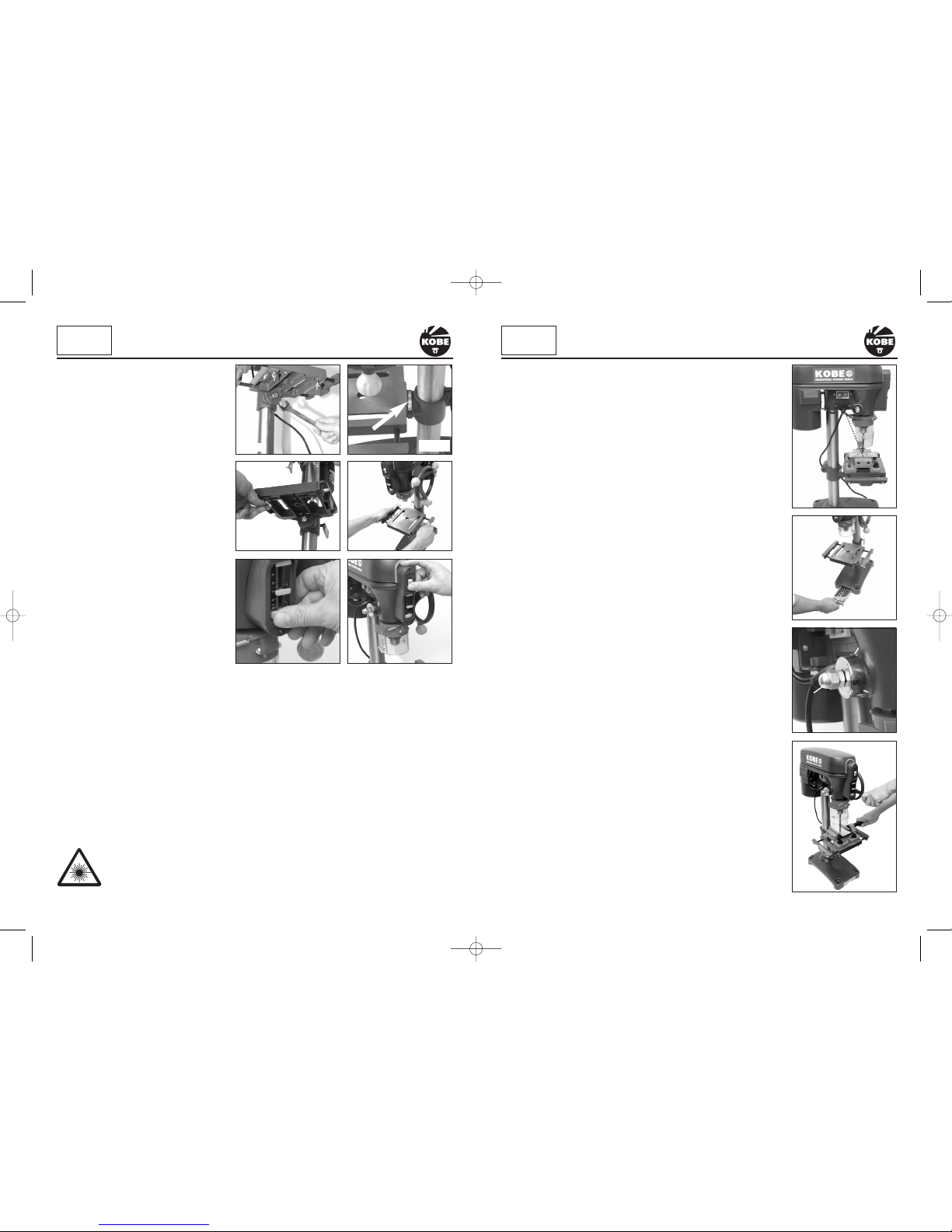
Fig.9
FITTING THE TABLE/SUPPORT ARM ASSEMBLY
Locate the table/support arm assembly (Fig.1) . Lower the table/
support arm assembly over the top of the column and line up with
the base plate. Tighten the support arm column clamp (Fig.5)
FITTING THE HEAD STOCK AND MOTOR ASSEMBLY
Locate the two grub screws in the side of the drill head stock and
motor assembly (Fig.7). Using a hexagonal key slacken the two grub
screws. Lift the drill head stock and motor assembly onto the
column. Make sure that it slides down and locates fully on the
column. Position the head stock and motor assembly, with the drill
head aligned over the table and base plate (Fig.6). Tighten the two
grub screws (Fig.7) to secure the head stock and motor assembly
into place. Retain the hexagon key for future adjustments.
FITTING THE CHUCK
The chuck has a taper fitting, simply place it onto the spindle adaptor
and tap with a soft rubber mallet (Fig.8). This is enough to secure in
it place and it should be tight enough. To make doubly sure, place a
piece of wood on the table and wind the manual feed handle to bring
the chuck down onto the wood pressing the chuck tighter onto the
spindle adaptor.
To remove, tap the chuck in a downward
motion with a soft mallet.
FITTING THE
TELESCOPIC GUARD
Position the clear plastic shield into the
red collar and secure in place with the two
small cross head screws. Place over the
chuck and locate onto the drill head collar
(Fig.9). Tighten the cross-head clamping
screw but don’t over tighten as this may
break the plastic body (Fig.10). Check that
the guard lifts easily and stays lifted to
change drills/cutting tools (Fig.11).
10
KOBE
INDUSTRIAL
POWER TOOLS
ASSEMBLY continued
7
Fig.6
USING THE 3 JAW CHUCK
Select the drill bit required, open the jaws and insert the drill shank centrally
into the chuck (Fig. 22). Rotate the chuck by hand until the jaws grip the drill
bit. The chuck has three holes around the chuck body. Using the chuck key,
exert an even torque to tighten, moving from one hole to the next until all
three holes have been covered. Do not over tighten otherwise you will have
difficulty removing the drill bit.
CHANGING THE SPINDLE SPEED
Unscrew the cross head screw securing the pulley guard casing
(Fig.23). Lift open the casing to reveal the pulley system (Fig.24).
Determine the spindle speed required using (Fig.29) which shows
drill sizes against material types. Identify the pulley
arrangement that gives the nearest spindle speed to
that required by referring to the drill pulley
configurations (Fig. 28).
Slacken the wing nut located on the right side of the
drill head casting (Fig.25).
This will release the tension on the drive belt. The
motor, situated at the rear of the machine can now slide
on the slide bar. Push it towards the front to enable belts
to be removed and re-positioned to achieve your required
speed setting.
To move the drive belts to the desired pulley
arrangement. Push the belt on the largest drive spindle
pulley towards the next smallest pulley and at the
same time rotate the drive spindle by hand until the
drive belt locates onto the next smallest pulley (be
careful not to trap your fingers between the belt and
pulley). Repeat this procedure until the desired pulley
arrangement has been achieved.
BELT TENSION
When the desired pulley arrangement has been
achieved, tension the drive belt by inserting a large
screwdriver or small pry bar between the the drill head
casting and the motor mounting (Fig.26). Lever the
motor mount away from the casting and tighten the wing nut. To check that the correct tension
has been achieved, press your finger onto the centre of the drive belt (Fig.27). The drive belt
should move approximately 13mm. Once this has been achieved, re-tighten the wing nut to lock
the motor slide bar in position.
Fig.7
KOBE
INDUSTRIAL
POWER TOOLS
SETTING UP & ADJUSTMENT
Fig.8
Fig.11
Fig.10
Fig.23
Fig.24
Fig.22
Fig.25
KBE-271-2030K_Instructions.qxd 09/06/2009 09:20 Page 7
Page 8
INTEGRAL BIT STORAGE TRAY
Conveniently located in the base of the Pillar Drill is a handy storage tray
for keeping your bits organised and close at hand. (Fig.19).
QUILL SPRING ADJUSTMENT
WARNING:
The quill spring is under extreme tension.
The quill spring is located in a chrome housing on the opposite side of the
feed shaft boss and returns the spindle to its uppermost position.
Adjustment is normally only required after many hours of use when it fails to
return the spindle to its uppermost position. With the spindle in its
uppermost position it can be seen that the chrome cover has a total of
three notches (Fig.20b) cut into the edge that align with the cast body of the
head stock. One of these notches is located over a cast peg (Fig. 20a) that
is part of the main casting.
WARNING: Before slackening the lock nuts ensure that the chrome
housing is held securely with a suitable grip or wrench. If not held
securely the quill spring will fully uncoil.
Carefully slacken the lock nuts (Fig.20c) only enough to allow the chrome
housing to be pulled out far enough to just clear the cast peg (Fig. 20a)
while holding the chrome cover with suitable grips. The spring is still under
tension and will try to uncoil as soon as it is released so be sure to resist
the torque. As soon as the chrome housing is able to clear the cast peg,
turn the chrome housing in an anti-clockwise direction until the next notch
locates onto the peg. While holding the chrome housing in this position
tighten the lock nuts. Do not over tighten otherwise you will damage the
chrome cover.
USING A MACHINE VICE
WARNING: The drill should never be used without the work piece being
securely held in a machine vice or clamped directly to the drill table.
The drill table is designed to accept a variety of machine vices which can be
fastened directly to the drill table; (Fig.21) gives an indication as to the type
of machine vice required.
Always secure the vice to the table with bolts, washers and nuts. If the drill
jams into the work piece, an unsecured machine vice will spin out of control
causing the drill to snap and possibly injure the operator.
ADJUSTING THE TABLE HEIGHT
To adjust the table height, slacken the
clamping lever at the rear of the table
support assembly (Fig. 5).
Slide the table up or down to desired
height. When the desired height has been
achieved, do not forget to re-secure the
clamping lever.
TILTING THE TABLE ± 45
°
Locate the securing bolt underneath the
table (Fig.12). With a suitable spanner or
wrench loosen the bolt. On the table
support assembly casting there is a
graduated 0 - 45° scale (Fig.13). Set the
table to the required angle and re-tighten
the bolt.
NOTE: The graduated scale is for guidance
only. We recommend the use of an
engineers protractor when setting any
angles
ADJUSTING THE TABLE WIDTH
Locate and loosen the wing nuts under the
table (Fig.14) and pull the side plates away from the main table (Fig.15). This will allow support for
larger machine vices and pieces of work (Fig.21). Once the side plates are in place don’t forget to
re-tighten the wing nuts.
SETTING THE DEPTH STOP
This facility is useful if a number of uniform depth holes are required in a work piece. The depth
stop is located on the front of the drilling head. To adjust, turn the thumb wheel (Fig.16) to the right
to increase the depth of travel of the drilling head or to the left to decrease the depth of travel.
LASER GUIDE
Located under the drilling head is a laser guide which is switched on using the on/off switch
located on the front of the drilling head above the depth stops (Fig.17). It provides target crosshairs (Fig.18) which once set on your first workpiece of a batch will facilitate the accurate
placement of subsequent pieces.
This Class 2 laser can potentially cause severe damage to eyes.
Never look directly into the laser beam or point the laser beam at people either
directly or indirectly through reflective surfaces.
8 9
Fig.14
Fig.16
Fig.15
Fig.20
Fig.19
KOBE
INDUSTRIAL
POWER TOOLS
SETTING UP & ADJUSTMENT
KOBE
INDUSTRIAL
POWER TOOLS
SETTING UP & ADJUSTMENT
Fig.12
Fig.13
Fig.17
Fig.18
20c
20a
20b
Fig.21
KBE-271-2030K_Instructions.qxd 09/06/2009 09:20 Page 8
 Loading...