

Page 1
ITEM #0268707
PORTABLE
AIR
COMPRESSOR
MODEL #VT6389
KOBALT® and the K Design® are registered
trademarks of LF, LLC. All Rights Reserved.
ATTACH YOUR RECEIPT HERE
Serial Number Purchase Date
Questions, problems, missing parts? Before returning to your retailer, call our customer
service department at 1-888-3KOBALT (1-888-356-2258), 8 a.m. - 8 p.m., EST,
Monday - Friday.
AB13473
Français p. 29
Español p. 59
kobalttools.com
1
IN638401AV 5/13
Page 2
TABLE OF CONTENTS
Safety Guidelines .......................................................................................................................... 3
Safety Information ......................................................................................................................... 3
Package Contents ......................................................................................................................... 6
Hardware Contents........................................................................................................................ 6
Preparation .................................................................................................................................... 7
Assembly Instructions.................................................................................................................... 8
Operating Instructions ................................................................................................................... 13
Care and Maintenance .................................................................................................................. 15
Troubleshooting ............................................................................................................................. 16
Warranty ........................................................................................................................................ 20
Replacement Parts List ................................................................................................................. 22
PRODUCT SPECIFICATIONS
COMPONENT SPECIFICATIONS
Model VT6389
HP 2
Number of Cylinders 2
Air Delivery @ 90 psi 5.5 CFM
Voltage 120 Volts / 15 Amps
Max Pressure 155 psi
COMPONENT SPECIFICATIONS
Oil Capacity 8.5 oz.
Tank Outlet Size 1/4 NPT
Depth 23 in.
Width 24 in.
Height 46 in.
Weight 178 lbs.
2
kobalttools.com
Page 3
SAFETY GUIDELINES
Please read and understand this entire manual before attempting to assemble, operate or install
the product. If you have any questions regarding the product, please call customer service at
1-888-3KOBALT (1-888-356-2258), 8:00 am - 8:00 pm, EST, Monday - Friday.
This manual contains information that is very important to know and understand. This information
is provided for SAFETY and to PREVENT EQUIPMENT PROBLEMS. To help recognize this
information, observe the following symbols.
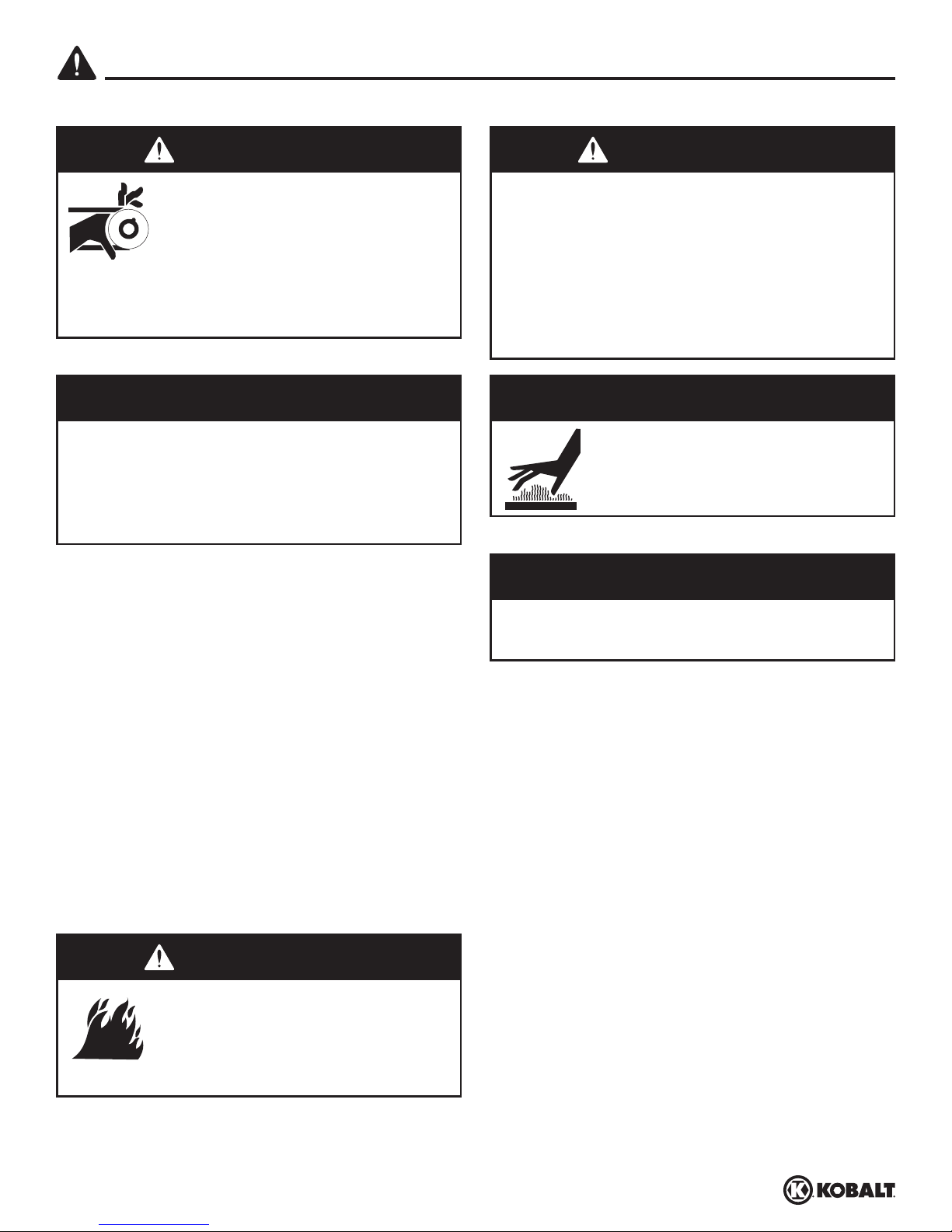
DANGER
Danger indicates an imminently hazardous
situation which, if not avoided, WILL result in
death or serious injury.
CAUTION
Caution indicates a potentially hazardous
situation which, if not avoided, MAY result in
minor or moderate injury.
SAFETY INFORMATION
CALIFORNIA PROPOSITION 65
WARNING
Handle with Care. This product or its power
cord may contain chemicals known to the
State of California to cause cancer and birth
defects or other reproductive harm. Wash
hands after handling.
GENERAL SAFETY
WARNING
Warning indicates a potentially hazardous
situation which, if not avoided, COULD result
in death or serious injury.
NOTICE
Notice indicates important information,
that if not followed, may cause damage to
equipment.
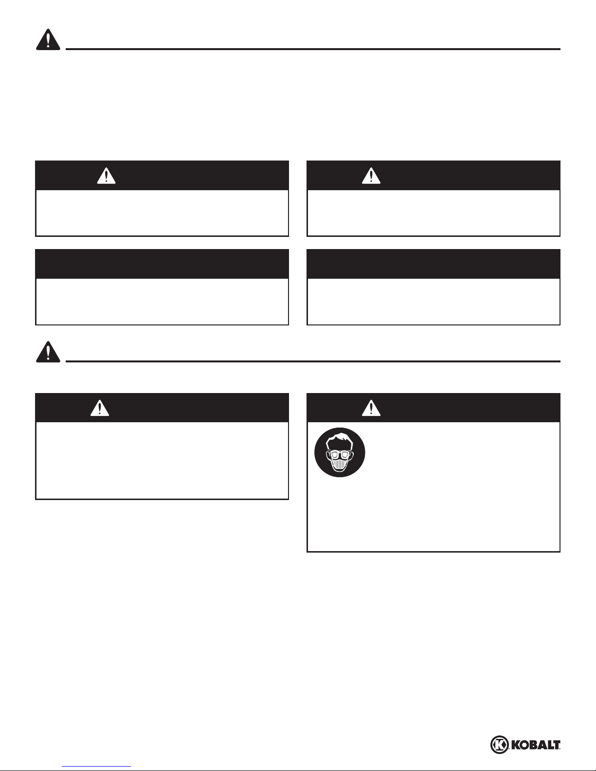
WARNING
Wear eye and mask protection.
You can create dust when you cut,
sand, drill or grind materials such
as wood, paint, metal, concrete,
cement, or other masonry. This
dust often contains chemicals
known to cause cancer, birth
defects, or other reproductive
harm. Wear protective gear.
Since the air compressor and other components (material pump, spray guns, filters, lubricators,
hoses, etc.) used, make up a high pressure pumping system, the following safety precautions must be
observed at all times:
1. Read all manuals included with this product carefully. Be thoroughly familiar with the controls
and the proper use of the equipment.
2. Follow all local electrical and safety codes as well as in the United States, the National Electrical
Codes (NEC) and Occupational Safety and Health Act (OSHA).
3. Only persons well acquainted with these rules of safe operation should be allowed to use the
compressor.
4. Keep visitors away and NEVER allow children in the work area.
5. Wear safety glasses and use hearing protection when operating the unit.
3
kobalttools.com
Page 4
SAFETY INFORMATION
GENERAL SAFETY (Continued)
6. Do not stand on or use the unit as a handhold.
7. Before each use, inspect compressed air system and electrical components for signs of damage,
deterioration, weakness or leakage. Repair or replace defective items before using.
8. Check all fasteners at frequent intervals for proper tightness.
9. Do not wear loose clothing or jewelry that will get caught in the moving parts of the unit.
10. Keep fingers away from a running compressor; fast moving and hot parts will cause injury and/or
burns.
11. If the equipment should start to vibrate abnormally, STOP the engine/motor and check
immediately for the cause. Vibration is generally a warning of trouble.
12. To reduce fire hazard, keep engine/motor exterior free of oil, solvent, or excessive grease.
13. Never attempt to adjust ASME safety valve. Keep safety valve free from paint and other
accumulations.
14. Tanks rust from moisture build-up, which weakens the tank. Make sure to drain tank regularly and
inspect periodically for unsafe conditions such as rust formation and corrosion.
15. Fast moving air will stir up dust and debris which may be harmful. Release air slowly when
draining moisture or depressurizing the compressor system.
DANGER
Risk of Personal Injury. This compressor/
pump is NOT equipped and should NOT be
used “as is” to supply breathing quality air. For
any application of air for human consumption,
you must fit the air compressor/pump with
suitable in-line safety and alarm equipment.
This additional equipment is necessary
to properly filter and purify the air to meet
minimal specifications for Grade D breathing
as described in Compressed Gas Association
Commodity Specification G 7.1, OSHA 29
CFR 1910. 134, and/or Canadian Standards
Associations (CSA).
DISCLAIMER OF WARRANTIES
In the event the compressor is used for the
purpose of breathing air application and
proper in-line safety and alarm equipment is
not simultaneously used, existing warranties
are void, and the Manufacturer disclaims any
liability whatsoever for any loss, personal injury
or damage.
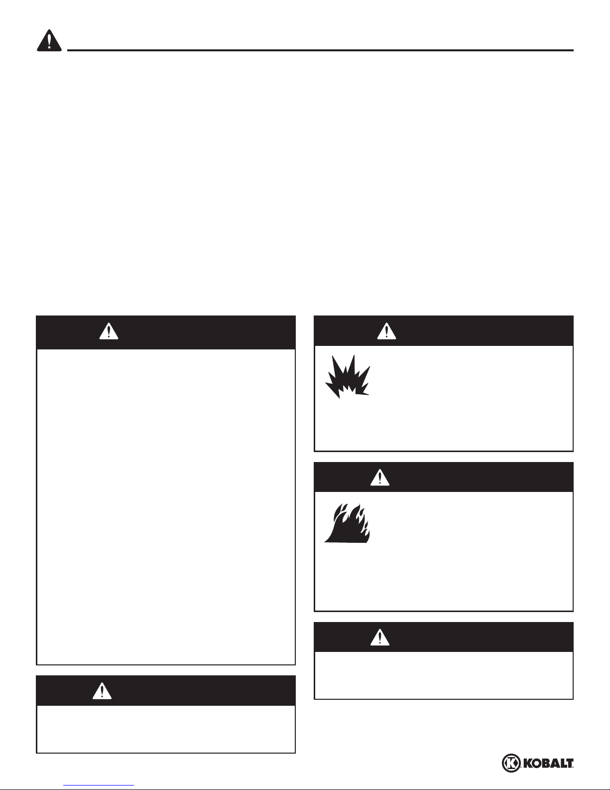
WARNING
DANGER
Risk of Explosion. Never attempt
to repair or modify a tank! Welding,
drilling or any other modifi cation
will weaken the tank resulting in
damage from rupture or explosion.
Always replace worn, cracked or
damaged tanks.
WARNING
Risk of Fire. Motors, electrical
equipment and controls can cause
electrical arcs that will ignite a
fl ammable gas or vapor. Never
operate or repair in or near a
fl ammable gas or vapor. Never
store fl ammable liquids or gases in
the vicinity of the compressor.
WARNING
Risk of Explosion. Never use plastic (PVC)
pipe for compressed air. Serious injury or
death could result.
Risk of Personal Injury and/or Equipment
Damage. Never install a shut-off valve
between the compressor pump and the tank.
4
kobalttools.com
Page 5
SAFETY INFORMATION
GENERAL SAFETY (Continued)
WARNING
Risk of Personal Injury. Never
operate compressor without a
beltguard. This unit can start
automatically without warning.
Personal injury or property
damage could occur from contact
with moving parts.
CAUTION
Do Not Overpressure. See compressor
specifi cation decal for maximum operating
pressure. Do not operate with pressure switch
or safety valves set higher than the maximum
operating pressure.
WARNING
Risk of Explosion. An ASME code safety
relief valve with a setting no higher than
the maximum allowable working pressure
(MAWP) MUST be installed in the tank for
this compressor. The ASME safety valve must
have suffi cient fl ow and pressure ratings to
protect the pressurized components from
bursting.
CAUTION
Risk of Personal Injury.
Compressor parts may be hot
even if the unit is stopped.
NOTICE
Unit Care and Maintenance. Drain liquid from
tank daily.
SPRAYING PRECAUTIONS
1. Do not smoke when spraying paint, insecticides, or other flammable substances.
2. Use a face mask/respirator when spraying and spray in a well-ventilated area to prevent health
and fire hazards.
3. Do not direct paint or other sprayed material at the compressor. Locate compressor as far away
from the spraying area as possible to minimize overspray accumulation on the compressor.
4. When spraying or cleaning with solvents or toxic chemicals, follow the instructions provided by
the chemical manufacturer.
WARNING
Risk of Fire. Do not spray
fl ammable materials in vicinity
of open fl ame or near ignition
sources including the compressor
unit.
5
kobalttools.com
Page 6

PACKAGE CONTENTS
D
C
E
K
J
H
I
A
G
B
F
PART DESCRIPTION QTY.
A Pressure Switch - AUTO/OFF Switch - In the AUTO position, the compressor
1
shuts off automatically when tank pressure reaches the maximum preset pressure.
After air is used from the tank and drops to a preset low level, the pressure switch
automatically turns the motor back on. In the OFF position, the compressor will not
operate. This switch should be in the OFF position when connecting or disconnecting
the power from the unit.
When the pressure switch turns the motor off you will hear air leaking out of the
pressure switch unloader valve for a short time. This releases the air pressure from
the discharge tube and allows the compressor to restart easier.
B ASME Safety Valve - This valve automatically releases air if the tank pressure
1
exceeds the preset maximum.
C Discharge tube - This tube carries compressed air from the pump to the check valve.
1
This tube becomes very hot during use. To avoid the risk of severe burns, never touch
the discharge tube.
6
kobalttools.com
Page 7
PACKAGE CONTENTS
PART DESCRIPTION QTY.
D Check valve - One-way valve that allows air to enter the tank, but prevents air in the
tank from flowing back into the compressor pump.
E Belt Guard - Covers the belt, motor pulley and flywheel. 1
F Tank Drain Valve - This valve is located on the bottom of the tank. Use this valve to
drain moisture from the tank daily to reduce the risk of corrosion.
G Tank Pressure Gauge - Indicates amount of air pressure stored in tank. 1
H Hose Pressure Gauge - Indicates amount of air pressure in hose used to operate
tools. This pressure is increased or decreased by the regulator.
I Regulator - The regulator controls the amount of air pressure released at the hose
outlet.
J Air Filter - Keeps debris and particulates out of the air flowing into the compressor. 1
K Breather - Vent for crankcase. 1
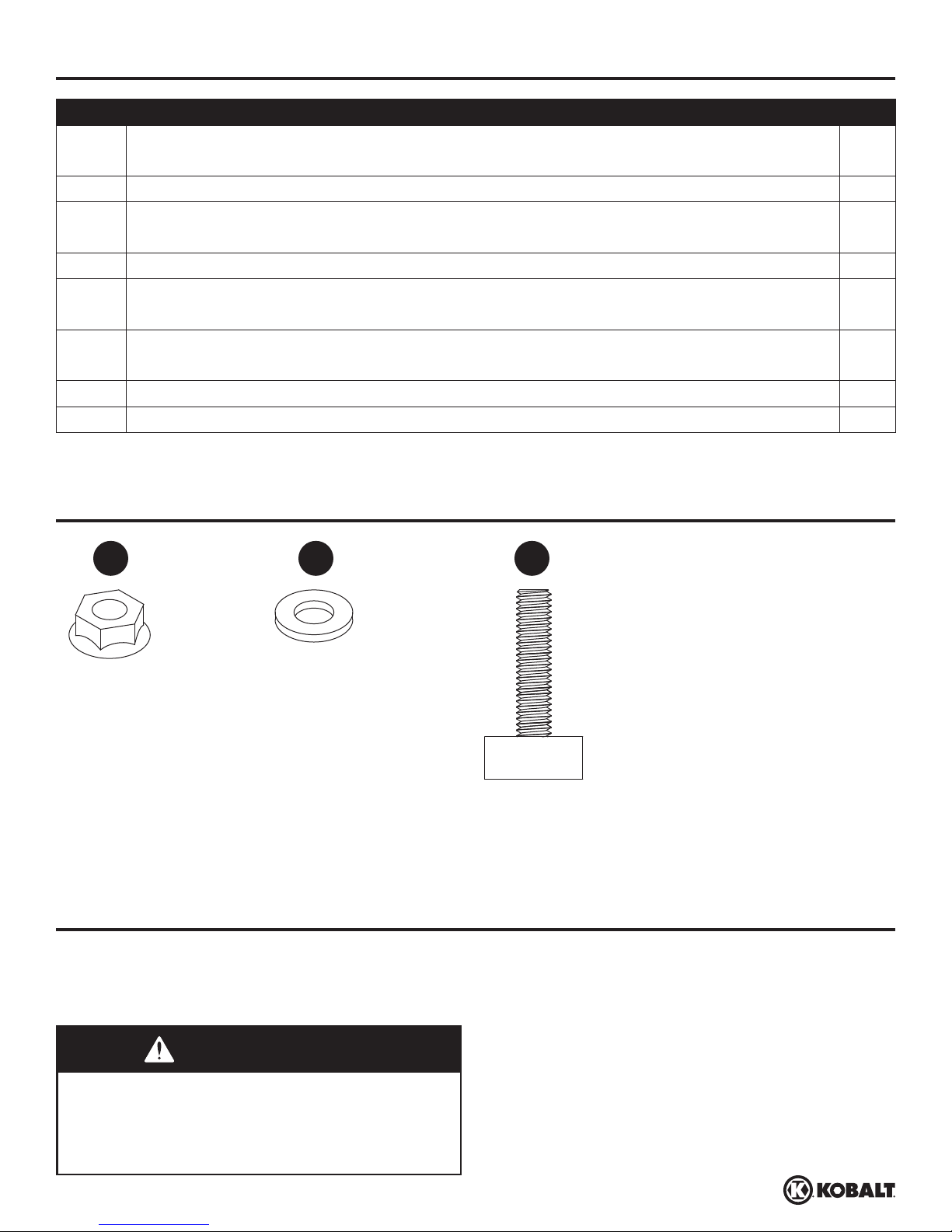
HARDWARE CONTENTS (shown actual size)
1
1
1
1
AA BB CC
5/16 inch x
18 Spinlock Nut
Qty. 2
PREPARATION
Before beginning installation and/or assembly of product, make sure all parts are present. Compare
parts with package contents list. If any part is missing or damaged, do not attempt to assemble or use
the product. Contact customer service for replacement parts and assistance.
5/16 inch Washer
Qty. 2
Rubber Foot
Qty. 2
WARNING
Risk of Personal Injury. Do not operate unit
if damaged during shipping, handling or use.
Damage may result in bursting and cause
injury or property damage.
7
kobalttools.com
Page 8
PREPARATION
Estimated Installation and Assembly Time: 20 minutes
Tools Required for Installation and Assembly (not included): Safety Glasses; Work Gloves; 9/16 inch
Socket and Ratchet; Adjustable Wrench
ADDITIONAL PARTS REQUIRED FOR USE [not included]
Parts - available at local hardware store.
1. Air Hose
2. Pipe Thread Sealant
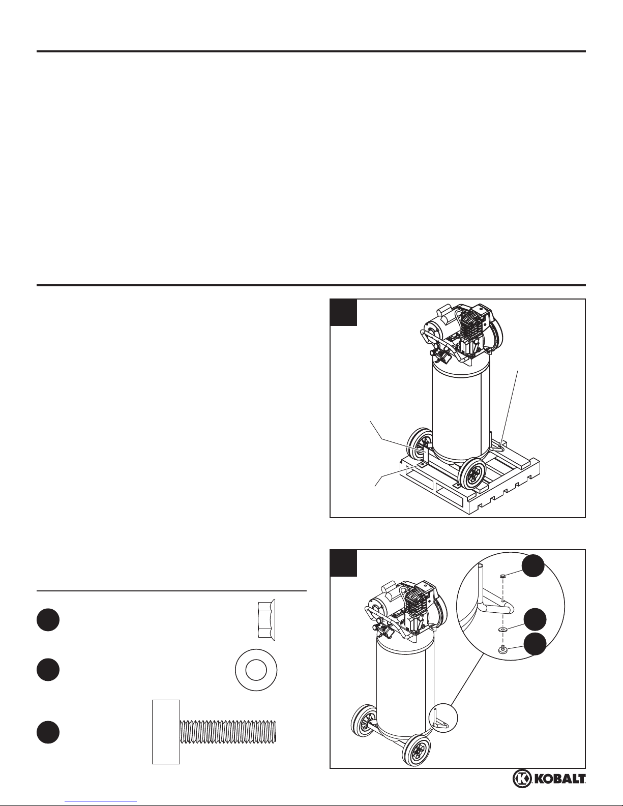
ASSEMBLY INSTRUCTIONS
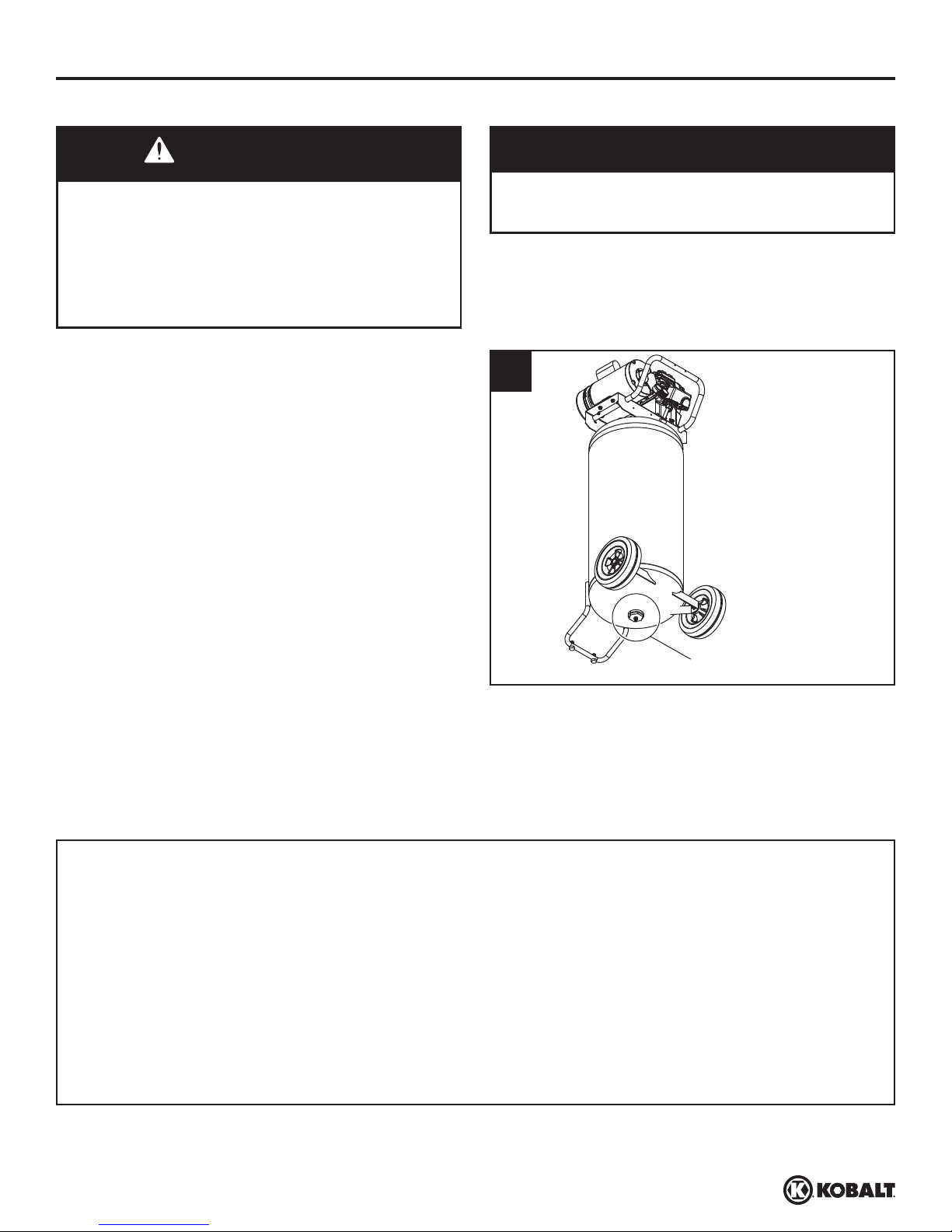
1. Unbolt the unit from the shipping skid. Use a
ratchet with a 9/16 inch socket. Remove the
unit from the skid. Discard shipping hardware
once removed.
1
Shipping
Bolt
2. Install rubber feet with nuts and washers.
Hardware Used
AA
Nut
BB
Washer x2
x2
Shipping
Bracket
Shipping
2
Bolt
AA
BB
CC
CC
Rubber Foot x2
8
kobalttools.com
Page 9
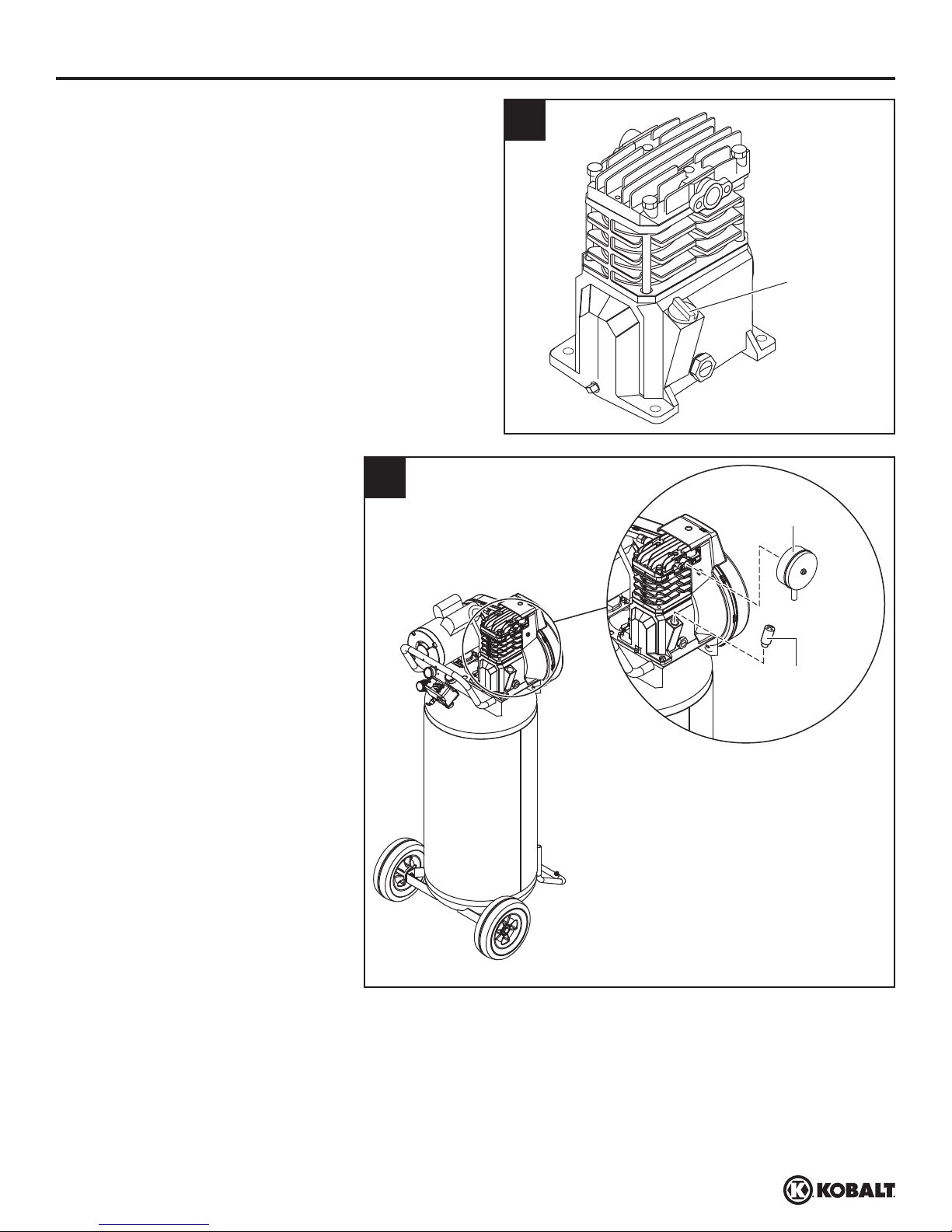
ASSEMBLY INSTRUCTIONS
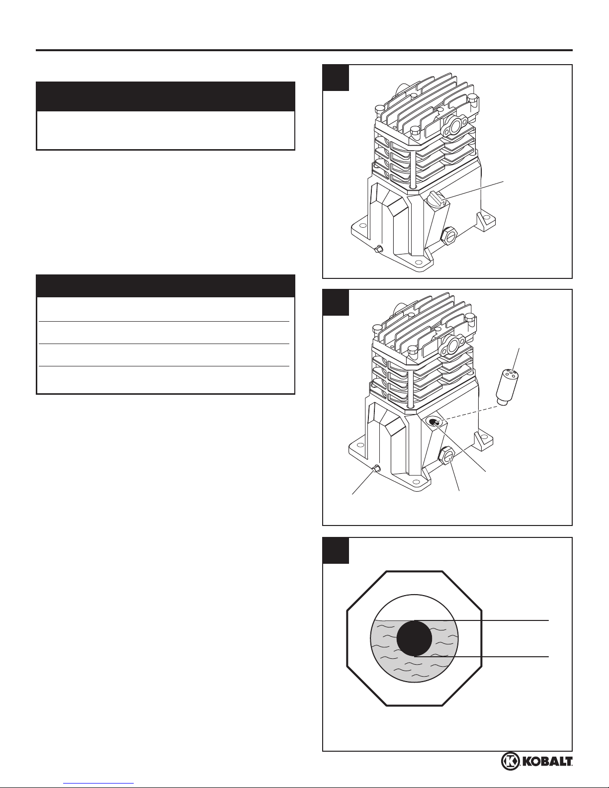
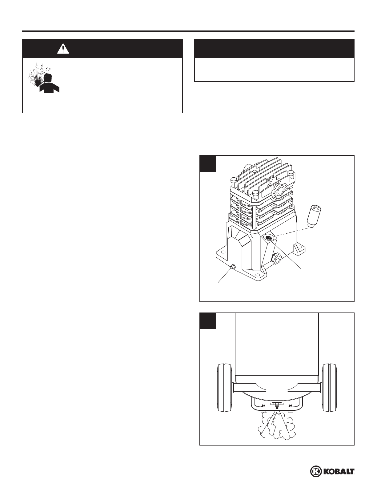
3. Remove cap from pump.
4. Install breather. Install air
fi lter.
3
Cap
4
Air Filter
Breather
9
kobalttools.com
Page 10
ASSEMBLY INSTRUCTIONS
LUBRICATION
CAUTION
Inspect Before Use. Check for proper oil level
before operating!
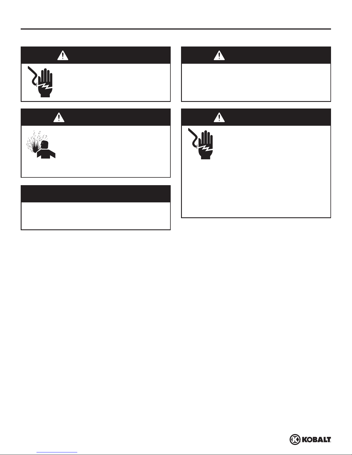
1
Remove cap from oil fill opening. See Figure
1. Install breather (found in parts bag with this
manual). See Figure 2. Check oil level; some
models are shipped with oil in the pump. See
specification label on compressor pump for the
proper oil capacity and oil type.
OIL INFORMATION
Kobalt Air Compressor Oil SKU 221008
Kobalt Synthetic Blend Oil SKU 221009
Mobil 1® synthetic 10W30
Oil Capacity 8.5 ounces
Do not use regular automotive oil. Additives in
regular motor oil can cause valve deposits and
reduce pump life. For maximum pump life, drain
and replace oil after the first hour of run time.
Cap
2
Breather
This pump has an oil sight glass as shown
in Figure 2. Oil level can be monitored and
maintained as shown in Figure 3.
10
Oil Drain
Plug
3
Oil Fill Area
Sight
Glass
Full
Low
Sight Glass
kobalttools.com
Page 11
ASSEMBLY INSTRUCTIONS
ELECTRICAL INFORMATION
DANGER WARNING
Risk of Shock. Improperly
grounded motors are shock
hazards. Make sure all the
equipment is properly grounded.
WARNING
Risk of Explosion. Disconnect,
tag and lock out power source,
then release all pressure from the
system before attempting to install,
service, relocate or perform any
maintenance.
NOTICE
Unit care and maintenance. Damage to the
motor from improper electrical voltage or
connection will void the warranty.
Risk of Personal Injury or Damage to
Personal Property. Overheating, short
circuiting and fi re damage will result from
inadequate wiring.
WARNING
Risk of Shock. Improper
installation of the grounding plug
is able to result in a risk of electric
shock. When repair or replacement
of the cord or plug is required, do
not connect the grounding wire
to either fl at blade terminal. The
wire with insulation having an
outer surface that is green with
or without yellow stripes is the
grounding wire.
Do not use an extension cord, use a longer air hose.
The 120 volt, 15 amp units can be operated on a 120 volt 15 amp circuit under the following conditions:
1. No other electrical appliances or lights are connected to the same branch circuit.
2. Voltage is 120 Volts.
3. Circuit is equipped with a 15 amp circuit breaker or a 15 amp slow blow fuse type T (For Canada
use Type D).
4. The length of copper wire between the outlet and circuit breaker is not longer than 40 feet of
14 AWG or 70 feet of 12 AWG.
11
kobalttools.com
Page 12
ASSEMBLY INSTRUCTIONS
GROUNDING
This product must be grounded. In the event of an electrical short circuit, grounding reduces the risk of
electric shock by providing an escape wire for the electric current. This product is equipped with a cord
having a grounding wire with an appropriate grounding plug. The plug must be plugged into an outlet
that is properly installed and grounded in accordance with all local codes and ordinances. Do not use
grounding adapter.
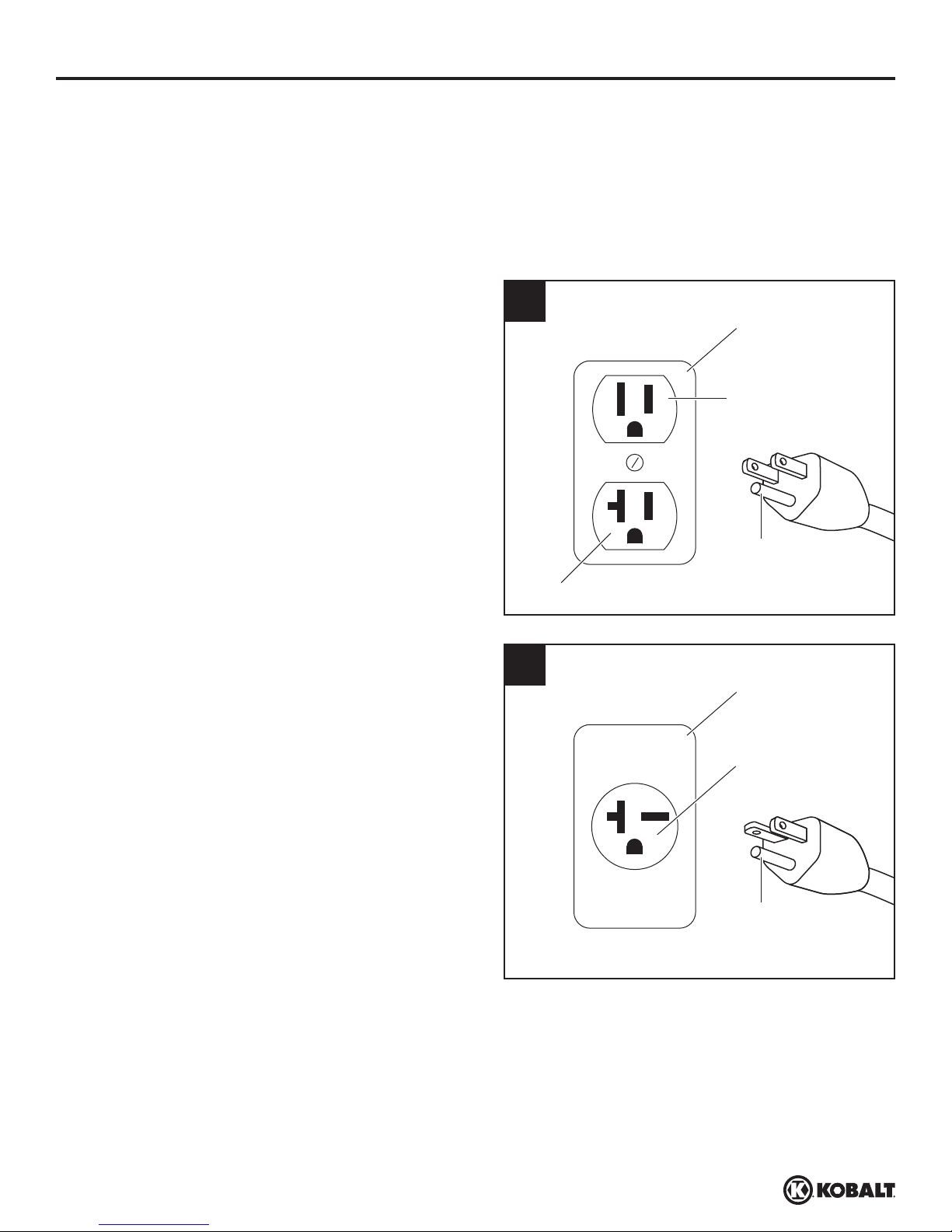
This product is for use on a nominal 120 volt
circuit and has a grounding plug similar to the
plug illustrated in Figure 1. If the listed conditions
cannot be met or if nuisance tripping of the
current protection device occurs, it may be
possible to operate the compressor from a 120
volt 20 amp circuit. See Figure 1.
Check motor data plate for 240 volt compatability.
A 240 volt unit must be operated on a 240 volt
circuit. The cord must only plug into a 240 volt
grounded outlet and may require a new cord and
plug. See Figure 2.
1
Outlet - 120V / 20A
2
Grounded
Outlet
Outlet - 120V / 15A
Ground
Pin
Grounded
Outlet
Outlet - 240V
Check with a qualified electrician or serviceman when the grounding instructions are not completely
understood, or when in doubt as to whether the product is properly grounded. Do not modify the plug
provided; if it does not fit the outlet, have the proper outlet installed by a qualified electrician. Only
connect the product to an outlet having the same configuration as the plug. Do not use an adapter with
this product.
12
Ground
Pin
kobalttools.com
Page 13
OPERATING INSTRUCTIONS
START-UP / BREAK-IN PROCEDURE
WARNING
Risk of Personal Injury. Do not attach air
tools to open end of the hose until start-up is
completed and the unit checks okay.
1. Check oil level per the Lubrication Section of this
manual.
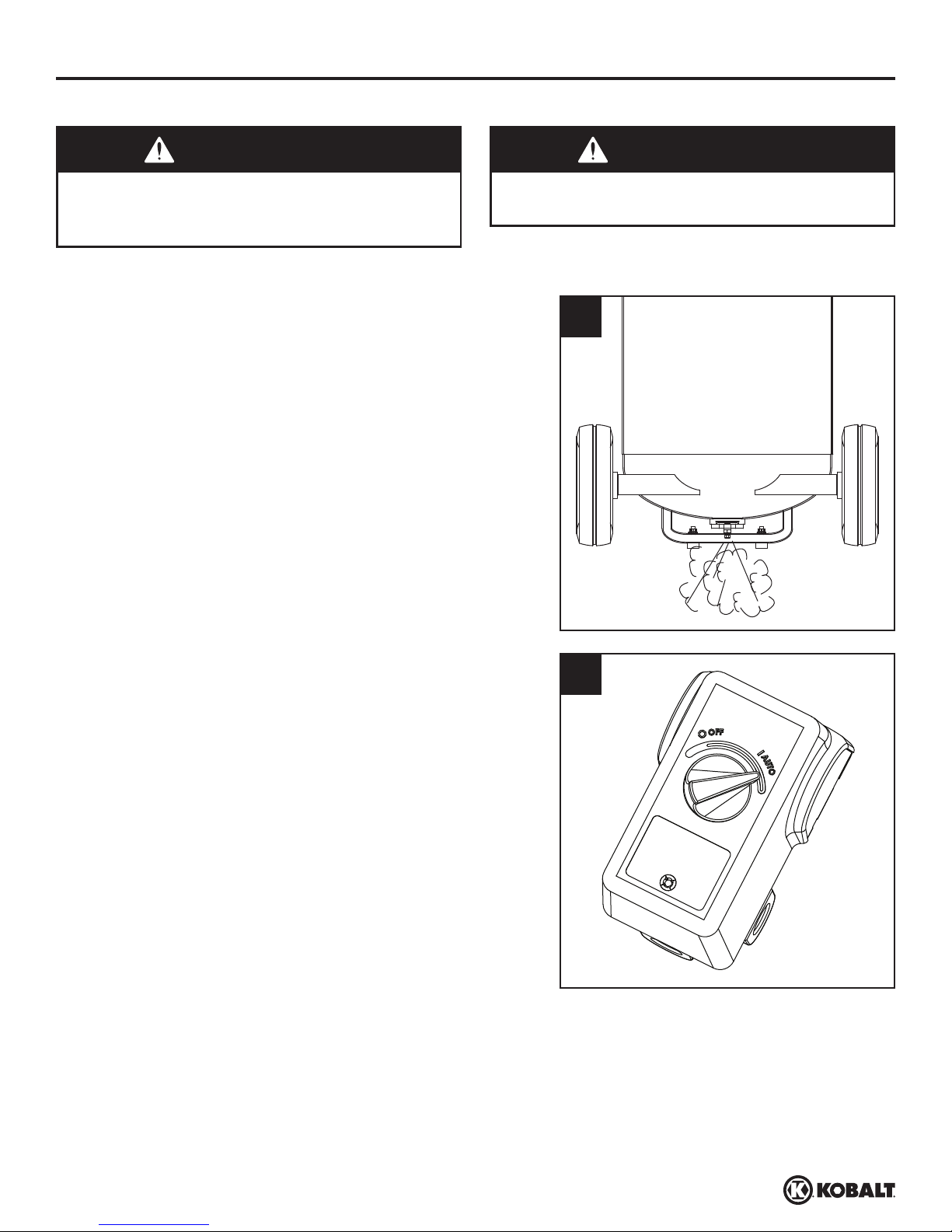
2. Open the bottom tank drain valve (see Figure 1).
Turn outlet valve to open air flow.
3. Plug unit in.
WARNING
Risk of Personal Injury. Never disconnect
threaded joints with pressure in tank!
1
4. Move pressure switch to the AUTO position to run the
unit (see Figure 2).
5. Run the unit for thirty (30) minutes at zero (0) psi
(under no load) to break in pump parts.
6. Move the pressure switch lever or knob to OFF
and turn tank drain valve to shut off air flow. The
compressor is now ready for use.
7. Change oil after first fifty (50) hours of operation.
Then perform oil changes every three (3) months.
COMPRESSOR USE
It is extremely important to operate the compressor in a clean, well-ventilated area where the
surrounding air temperature will not be more than 100°F. Do not locate the compressor air inlet near
steam, paint spray, sandblast areas or any other source of contamination.
2
13
kobalttools.com
Page 14
OPERATING INSTRUCTIONS
ON/OFF CYCLING OF COMPRESSOR
WARNING
Risk of Bursting. Drain tank every day to
prevent corrosion and possible injury due to
tank damage. Do not operate drain with more
than 40 psi in tank or drain valve may be
damaged. Drain tank of moisture daily using
the drain valve in the bottom of the tank.
In the AUTO position, the compressor pumps air
into the tank. When a shut-off (preset “cut-out”)
pressure is reached, the compressor automatically
shuts off.
If the compressor is left in the AUTO position
and air is depleted from the tank by use of a
tire chuck, tool, etc., the compressor will restart
automatically at its preset “cut-in” pressure. When
a tool is being used continuously, the compressor
will cycle on and off automatically.
NOTICE
Unit care and maintenance. Drain liquid from
tank daily.
1
In the OFF position, the compressor will not
operate.
Bottom Drain Valve
Drain Tank. Disconnect, tag, unplug and lock out
power source; release pressure. Drain moisture
from tank by opening drain valve underneath tank
(See Figure 1).
MOISTURE IN COMPRESSED AIR
Moisture in compressed air will form into droplets as it comes from an air compressor pump.
When humidity is high or when a compressor is in continuous use for an extended period of time,
this moisture will collect in the tank. When using a paint spray or sandblast gun, this water will
be carried from the tank through the hose, and out of the gun as droplets mixed with the spray
material.
IMPORTANT: This condensation will cause water spots in a paint job, especially when spraying
other than water based paints. If sandblasting, it will cause the sand to cake and clog the gun,
rendering it ineffective. A fi lter in the air line, located as near to the gun as possible, will help
eliminate this moisture.
14
kobalttools.com
Page 15
CARE AND MAINTENANCE
WARNING
Risk of Explosion. Disconnect,
tag and lock out power source,
then release all pressure from the
system before attempting to install,
service, relocate or perform any
maintenance.
All repairs should be performed by an authorized service representative.
For efficient operation, perform the following maintenance.
1. Disconnect, tag, unplug and lock out power
source; clean debris from motor, flywheel,
tank, air lines and pump cooling fins.
2. Maintain proper oil level. Refer to Lubrication
section for details.
3. Change oil.
a. Allow compressor to run and warm up
oil. Disconnect, tag and lock out power
source.
b. Position a pan under pump.
c. Remove oil drain plug (See Figure 1).
Allow oil to collect in pan.
d. Replace drain plug, fill pump to full level
(See Figure 1). See Lubrication section of
this manual.
4. Drain Tank. Disconnect, tag and lock out
power source; release pressure. Drain
moisture from tank by opening drain valve
underneath tank (See Figure 2).
5. Check air filter to be sure it is clean. Replace
filter if filter is dirty.
Unit care and maintenance. Drain liquid from
tank daily.
1
Oil Drain
Plug
2
NOTICE
Oil Fill Area
15
kobalttools.com
Page 16
CARE AND MAINTENANCE
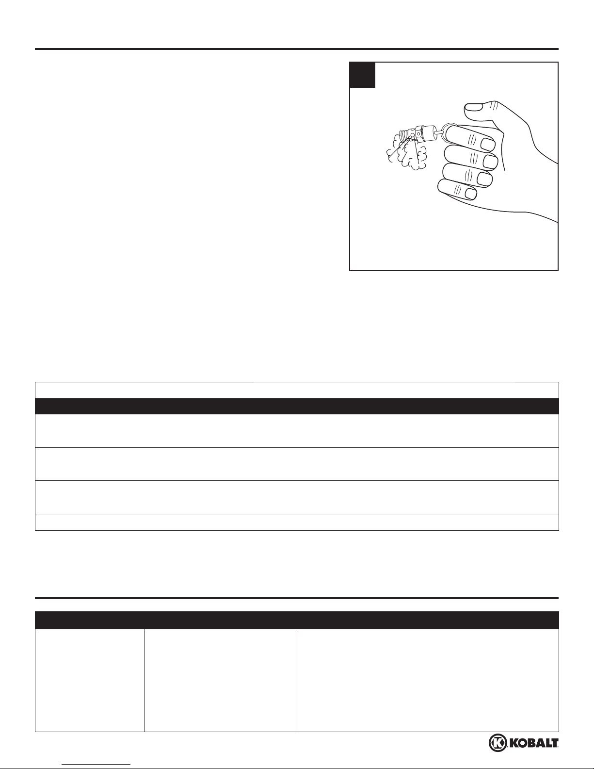
6. Check the safety valve by performing the following
steps:
a. Restore power to unit; turn pressure switch to the
AUTO position. Run until unit reaches 90 psi.
Turn pressure switch to OFF position.
b. Wearing safety glasses and hearing protection,
pull the ring on the safety valve to release
pressure from compressor tank. Protect yourself
from fast-moving air being released; do not allow
fast-moving air to be directed toward your face
(See Figure 3).
c. The safety valve should automatically close at
approximately 40-50 psi. If the safety valve does
not allow air to be released when you pull on the
ring, or if it does not close automatically, it MUST
be replaced.
7. Check belt for signs of excessive wear. If belt shows
signs of wear, replace it. Check belt for proper
tension / alignment.
3
TECHNICAL SERVICE
For information regarding the operation or repair of this product, please call 1-888-3KOBALT
(1-888-356-2258).
MAINTENANCE SCHEDULE
OPERATION DAILY WEEKLY MONTHLY 3 MONTHS
CHECK OIL LEVEL
DRAIN TANK
CHECK AIR FILTER
CHECK SAFETY VALVE
CLEAN UNIT
CHECK BELT TIGHTNESS
CHANGE OIL*
●
●
●
●
●
●
●
* Change oil after fi rst fi fty (50) hours of operation then perform oil changes every three (3)
months.
TROUBLESHOOTING
PROBLEM POSSIBLE CAUSE CORRECTIVE ACTION
Low discharge
pressure
1. Air demand exceeds
pump capacity
2. Restricted air intake 2. Clean or replace the air filter element.
3. Air leaks (fittings,
tubing on compressor,
or plumbing outside of
system)
1. Reduce air demand or use a compressor with
more capacity.
3. Listen for escaping air. Apply soap solution to
all fittings and connections. Bubbles will appear
at points of leakage. Tighten or replace leaking
fittings or connections. Use pipe thread sealant.
16
kobalttools.com
Page 17
TROUBLESHOOTING
PROBLEM POSSIBLE CAUSE CORRECTIVE ACTION
Low discharge
pressure
(Continued)
Excessive noise
(knocking)
4. Blown gaskets 4. Replace any gaskets proven faulty on
inspection.
5. Leaking or damaged
valves
5. Remove head and inspect for valve breakage,
misaligned valves, damaged valve seats, etc.
Replace defective parts and reassemble.
CAUTION
Unit care and maintenance. Install a new
head gasket each time the head is removed.
1. Loose motor pulley or
flywheel
2. Loose fasteners on pump
or motor
3. Lack of oil in crankcase 3. Check for proper oil level; if low, check for
4. Worn connecting rod 4. Replace connecting rod. Maintain oil level and
5. Worn piston pin bores 5. Remove piston assemblies from the
6. Piston hitting the valve
plate
7. Noisy check valve in
compressor system
1. Tighten pulley / flywheel clamp bolts and setscrews.
2. Tighten fasteners.
possible damage to bearings. Dirty oil can
cause excessive wear.
change oil more frequently.
compressor and inspect for excess wear.
Replace excessively worn piston pin or pistons,
as required. Maintain oil level and change oil
more frequently.
6. Remove the compressor head and valve plate
and inspect for carbon deposits or other foreign
matter on top of piston. Replace head and
valve plate using new gasket. See Lubrication
section for recommended oil.
7. Replace check valve.
Large quantity of oil
in the discharge air
NOTE: In an oillubed compressor
there will always be
a small amount of
oil in the air stream.
1. Worn piston rings 1. Replace with new rings. Maintain oil level and
2. Compressor air intake
restricted
3. Excessive oil in
compressor
4. Wrong oil viscosity 4. Use Mobil 1
DANGER
Risk of Explosion. Do not
disassemble check valve with air
pressure in tank.
change oil more frequently.
2. Clean or replace filter. Check for other
restrictions in the intake system.
3. Drain down to full level.
®
10W-30 or full synthetic.
17
kobalttools.com
Page 18
TROUBLESHOOTING
PROBLEM POSSIBLE CAUSE CORRECTIVE ACTION
Water in discharge
air / tank
Motor hums and
runs slowly or not
at all
Normal operation. The
amount of water increases
with humid weather
1. Low voltage 1. Check incoming voltage. It should be
2. Use of extension cord 2. Do not use an extension cord. Use longer air
3. Too many devices on
same circuit
4. Loose electrical
connections
5. Malfunctioning pressure
switch - contacts will not
close
6. Malfunctioning check
valve
1. Drain tank more often. At least daily.
2. Add a filter to reduce the amount of water in the
air line.
approximately 230 volts. Motor will not run
properly on 208 volts. Low voltage could
be due to wires (from electrical source to
compressor) being too small in diameter and /
or too long. Have a qualified electrician check
these conditions and make repairs as needed.
hose with larger diameter.
3. Limit the circuit to the use of compressor only
4. Check all electrical connections.
5. Replace pressure switch.
6. Replace check valve.
Reset mechanism
cuts out repeatedly
or circuit breaker
trips repeatedly
DANGER
Risk of Explosion. Do not
disassemble check valve with air
pressure in tank.
7. Defective unloader valve
on pressure switch
8. Defective motor
capacitor(s)
9. Defective motor 9. Replace motor.
1. Lack of proper
ventilation / room
temperature too high
2. Too many devices on
same circuit
3. Restricted air intake 3. Clean or replace filter element.
4. Loose electrical
connection
5. Pressure switch shut-off
pressure set too high
7. Replace unloader valve.
8. Replace capacitor(s).
1. Move compressor to well-ventilated area.
2. Limit the circuit to the use of only the air
compressor.
4. Check all electrical connections.
5. Replace pressure switch.
18
kobalttools.com
Page 19
TROUBLESHOOTING
PROBLEM POSSIBLE CAUSE CORRECTIVE ACTION
Reset mechanism
cuts out repeatedly
or circuit breaker
trips repeatedly
(Continued)
Tank does not hold
pressure when
compressor is off
and the shut off
valve is closed
6. Malfunctioning check
valve
6. Replace check valve.
DANGER
Risk of Explosion. Do not
disassemble check valve with air
pressure in tank.
7. Defective unloader valve
on pressure switch
8. Defective motor
capacitor(s)
9. Malfunctioning motor 9. Replace motor.
1. Air leaks (fittings, tubing
on compressor, or
plumbing outside system)
2. Worn check valve 2. Replace check valve.
7. Replace unloader valve.
8.Replace capacitor(s).
1. Check all connections with soap and water
solution. Tighten; or remove and apply sealant
to threads, then reassemble.
DANGER
3. Check tank for cracks or
pin holes
Pressure switch
continuously
blows air out the
unloader valve
Excessive vibration 1. Loose fasteners on pump
Malfunctioning check valve Replace the check valve if the unloader valve on
or motor
2. Belt needs replaced 2. Replace with correct size.
3. Belt alignment 3. Align flywheel and pulley.
Risk of Explosion. Do not
disassemble check valve with air
pressure in tank.
3. Replace tank. Never repair a damaged tank.
the pressure switch bleeds off constantly when
unit shuts off.
DANGER
Risk of Explosion. Do not
disassemble check valve with air
pressure in tank.
1. Tighten fasteners.
19
kobalttools.com
Page 20
TROUBLESHOOTING
PROBLEM POSSIBLE CAUSE CORRECTIVE ACTION
Pressure switch
does not release
air when the unit
shuts off
Malfunctioning unloader
valve on pressure switch
Replace the unloader valve if it does not release
the pressure for a short period of time when the
unit shuts off.
DANGER
Risk of Explosion. Do not
disassemble unloader valve with
air pressure in tank.
WARRANTY
1. DURATION: From the date of purchase by the original purchaser as follows: Three Years.
2. WHO GIVES THIS WARRANTY: Campbell Hausfeld / Scott Fetzer Company, 100 Production
Drive, Harrison, Ohio, 45030.
3. WHO RECEIVES THIS WARRANTY (PURCHASER): The original purchaser (other than for
purposes of resale) of the compressor.
4. WHAT PRODUCTS ARE COVERED BY THIS WARRANTY: This air compressor.
5. WHAT IS COVERED UNDER THIS WARRANTY: Parts and Labor to remedy substantial
defects due to material and workmanship during the first year of ownership with the exceptions
noted below. Parts only to remedy substantial defects due to material and workmanship during
remaining term of coverage with exceptions noted below.
6. WHAT IS NOT COVERED UNDER THIS WARRANTY:
A. Implied warranties, including those of merchantability and FITNESS FOR A PARTICULAR
PURPOSE ARE LIMITED FROM THE DATE OF ORIGINAL PURCHASE AS STATED IN
THE DURATION. If the compressor is used for commercial, industrial or rental purposes, the
warranty will apply for ninety (90) days from the date of purchase. Four cylinder single stage
compressors and two-stage compressors are not limited to a ninety (90) day warranty when
used in commercial or industrial applications. Some States do not allow limitations on how
long an implied warranty lasts, so the above limitations may not apply to you
B. ANY INCIDENTAL, INDIRECT, OR CONSEQUENTIAL LOSS, DAMAGE, OR EXPENSE
THAT MAY RESULT FROM ANY DEFECT, FAILURE, OR MALFUNCTION OF THE
CAMPBELL HAUSFELD PRODUCT. Some States do not allow the exclusion or limitations of
incidental or consequential damages, so the above limitation or exclusion may not apply to
you.
C. Any failure that results from an accident, purchaser’s abuse, neglect or failure to operate
products in accordance with instructions provided in the owner’s manual(s) supplied with
compressor.
D. Pre-delivery service, e.g. assembly, oil or lubricants, and adjustment.
E. Items or service that is normally required to maintain the product, i.e. lubricants, filters and
gaskets, etc.
F. Gasoline engines and components are expressly excluded from coverage under this limited
warranty. The Purchaser must comply with the warranty given by the engine manufacturer
which is supplied with the product
20
kobalttools.com
Page 21

WARRANTY
G. Additional items not covered under this warranty:
1. Excluded items pertaining to All Compressors
a. Any component damaged in shipment or any failure caused by installing or operating
unit under conditions not in accordance with installation and operation guidelines or
damaged by contact with tools or surroundings.
b. Pump or valve failure caused by rain, excessive humidity, corrosive environments or
other contaminants.
c. Cosmetic defects that do not interfere with compressor functionality.
d. Rusted tanks, including but not limited to rust due to improper drainage or corrosive
environments.
e. The following components are considered normal wear items and are not covered
after the first year of ownership. Electric motor, check valve, pressure switch, regulator,
pressure gauges, hose, tubing, pipe, fittings and couplers, screws, nuts, hardware
items, belts, pulleys, flywheel, air filter and housing, gaskets, seals, oil leaks, air leaks,
oil consumption or usage, piston rings.
f. Tank drain valves.
g. Damage due to incorrect voltage or improper wiring.
h. Other items not listed but considered general wear parts.
i. Pressure switches, air governors, load/unload devices, throttle control devices and
safety valves modified from factory settings.
j. Damage from inadequate filter maintenance.
k. Induction motors operated with electricity produced by a generator.
2. Excluded items specific to Lubricated Compressors:
a. Pump wear or valve damage caused by using oil not specified.
b. Pump wear or damage caused by any oil contamination.
c. Pump wear or damage caused by failure to follow proper oil maintenance guidelines,
operation below proper oil level or operation without oil.
H. Labor, service call, or transportation charges after the first year of ownership of stationary
compressors. Stationary compressors are defined as not including a handle or wheels.
7. RESPONSIBILITIES OF WARRANTOR UNDER THIS WARRANTY: Repair or replace, at
Warrantor’s option, compressor or component which is defective, has malfunctioned and/or
failed to conform within the duration of the specific warranty period.
8. RESPONSIBILITIES OF PURCHASER UNDER THIS WARRANTY:
A. Provide dated proof of purchase and maintenance records.
B. Call customer service at 1-888-3KOBALT (1-888-356-2258) to obtain your warranty service
options. Freight costs must be borne by the purchaser.
C. Use reasonable care in the operation and maintenance of the products as described in the
owner’s manual(s).
D. Repairs requiring overtime, weekend rates, or anything beyond the standard manufacturer
warranty repair labor reimbursement rate.
E. Time required for any security checks, safety training, or similar for service personnel to gain
access to facility.
F. Location of unit must have adequate clearance for service personnel to perform repairs and
be easily accessible.
9. WHEN WARRANTOR WILL PERFORM REPAIR OR REPLACEMENT UNDER THIS
WARRANTY: Repair or replacement will be scheduled and serviced according to the normal
work flow at the servicing location, and depending on the availability of replacement parts.
This Limited Warranty applies in the U.S., Canada and Mexico only and gives you specific legal
rights. You may also have other rights which vary from state to state or country to country.
21
kobalttools.com
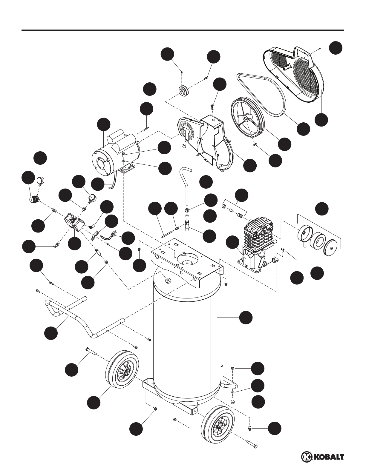
Page 22

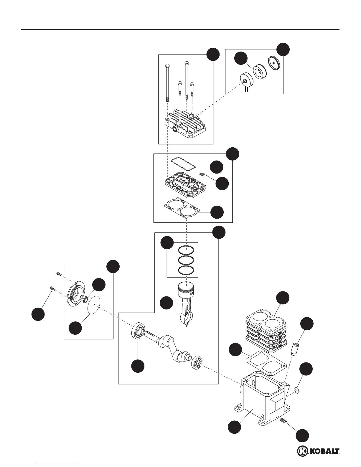
REPLACEMENT PARTS LIST
35
23
24
34
25
36
37
52
32
50
7
16
26
17
15
29
40
31
33
30
28
18
14
22
21
44
19
8
9
13
11
10
20
41
12
5
48
51
49
42
43
1
6
4
49
39
3
38
27
2
22
kobalttools.com
Page 23

REPLACEMENT PARTS LIST
For replacement parts, call our customer service department at 1-888-3KOBALT (1-888-356-2258),
8:00 am - 8:00 pm, EST, Monday - Friday.
PART DESCRIPTION PART NUMBER QTY.
1 Tank AR066500CG 1
2 Drain valve D-1403 1
3 Wheel WA006000AV 2
4 Axle bolt ST084700AV 2
5 Handle screw ST073273AV 4
6 Handle HL038101AV 1
7 Regulator RE300900AV 1
8 1/4 inch Nipple HF002401AV 1
9 ASME Safety Valve V-215109AV 1
10 Power cord EC012602AV 1
11 Strain relief CW209600AV 1
12 Strain relied screw ST209800AV 1
13 Pressure switch CW218700AV 1
14 Unloader CW210001AV 1
15 Reducer ST071407AV 1
16 Gauge GA016310AV 1
17 Exhaust tube VT046800AP 1
18 Compression nut ST033001AV 1
19 Ferrule ST085200AV 1
20 Check valve CV221502AJ 1
21 Push-in fitting ST081301AV 1
22 Unloader tube ST117802AV 1
23 Plascrew ST058502AV 1
24 #10 - 24 Selftapping screw ST073278AV 3
25 Self tapping screw ST073269AV 1
26 Motor cord EC012800AV 1
27 Rubber foot ST162601AV 2
28 Beltguard (front) BG222200AV 1
29 Beltguard (back) BG222300AV 1
30 Belt BT013000AV 1
31 Flywheel with key PU015901SJ 1
32 Gauge GA016300AV 1
33 Key (included with flywheel) Not Available 1
34 Pulley PU015200AV 1
23
Continued on next page
kobalttools.com
Page 24
REPLACEMENT PARTS LIST
35
23
24
34
25
36
37
52
32
50
7
16
26
17
15
29
40
31
33
30
28
18
14
22
21
44
19
8
9
13
11
10
20
41
12
5
48
51
49
42
43
1
6
4
49
39
3
38
27
2
24
kobalttools.com
Page 25

REPLACEMENT PARTS LIST
▲
▲
For replacement parts, call our customer service department at 1-888-3KOBALT (1-888-356-2258),
8:00 am - 8:00 pm, EST, Monday - Friday.
PART DESCRIPTION PART NUMBER QTY.
35 1/4 inch - 20 x 1/2 inch Square head ST012200AV 1
36 Key KE000903AV 1
37 Electric motor MC015502SJ 1
38 Nut ST033500AV 2
39 Washer ST070930AV 2
40 Compression connector assembly ST018300AV 1
41 Pump VT480000AV 1
42 Tapping screw ST073275AV 4
43 Filter Element VH901800AV 1
44 Filter VH901700AV 1
45
46
47
Inspection port reducer (
)
Inspection port o-ring (▲)
Inspection port reducer 1-1/2 inch (▲)
PG150006AV 1
ST070191AV 2
PG150008AV 1
48 1/4 inch Nipple ST016800AV 1
49 5/16 inch x 18 Spinlock nut ST146001AV 6
50 5/16 inch Washer ST011200AV 4
51 1/2 inch - 14 x 1/4 inch Reducer ST071428AV 1
52 5/16 inch - 18 x 3/4 inch Hex head screw ST070692AV 4
53
Warning label (▲)
Not shown
DK711200AV 1
25
kobalttools.com
Page 26
REPLACEMENT PARTS LIST
16
17
20
14
15
21
5
13
10
11
12
9
7
4
6
3
2
8
19
26
1
18
kobalttools.com
Page 27
REPLACEMENT PARTS LIST
For replacement parts, call our customer service department at 1-888-3KOBALT (1-888-356-2258),
8:00 am - 8:00 pm, EST, Monday - Friday.
PART DESCRIPTION PART NUMBER QTY.
1 Crankcase VT040300AV 1
2 Crankcase gasket
▲
3 Breather VH901100AV 1
4 Cylinder VT040715AV 1
5 Cylinder gasket
▲
6 Connecting rod and piston assembly VT020500AV 2
7 Piston ring set VT911200AV 2
8 Ball bearing ST084202AV 2
9 Crankshaft, bearings, rods, piston, rings assembly VT040650AV 1
10 O-ring
▲
11 Oil seal ST129700AV 1
12 Bearing cap assembly VT040200AJ 1
13 M6 x 10 mm screw
❋
14 Valve plate assembly VT491100AV 1
15 Valve plate molded seal
▲
16 Cylinder head and fasteners TQ900800AJ 1
17 Air fi lter assembly VH901700AV 1
18 1/8 inch - 27 Oil drain plug ST022300AV 1
19 Sight glass ST191700AV 1
20 Air fi lter element VH901800AV 1
21 O-ring VT036700AV 1
1
1
1
4
1
REPLACEMENT PARTS KITS
▲
❋
Gasket Kit VT470900AJ
Standard hardware item
27
kobalttools.com
Page 28

NOTES
KOBALT® and the K Design® are registered
trademarks of LF, LLC. All Rights Reserved.
28
Printed in U.S.A.
kobalttools.com
Page 29

ARTICLE #0268707
COMPRESSEUR
D’AIR
PORTATIF
MODÈLE #VT6389
Kobalt® et le motif K&Design® sont des marques de
commerce déposées de LF, LLC. Tous droits réservés.
JOIGNEZ VOTRE REÇU ICI
Numéro de série Date d’achat
Des questions, des problèmes, des pièces manquantes? Avant de retourner l’article
au détaillant, appelez notre service à la clientèle au 1 888 3KOBALT (1 888 356-2258),
entre 8 h et 20 h (HNE), du lundi au vendredi.
29
kobalttools.com
IN638401AV 5/13
Page 30

TABLE DES MATIÈRES
Consignes de sécurité ................................................................................................................... 31
Contenu de l’emballage ................................................................................................................. 34
Quincaillerie incluse....................................................................................................................... 35
Préparation .................................................................................................................................... 36
Instructions pour l’assemblage ...................................................................................................... 36
Mode d’emploi ............................................................................................................................... 42
Entretien ........................................................................................................................................ 44
Dépannage .................................................................................................................................... 46
Garantie ......................................................................................................................................... 50
Liste des pièces de rechange ........................................................................................................ 52
CARACTÉRISTIQUES DU PRODUIT
COMPOSANTE CARACTÉRISTIQUES
Modèle VT6389
HP 2
Nombre de cylindres 2
Débit d’air à 90 lb/po
2
5,5 pi3/min
Tension 120 volts / 15 A
Pression maximale 155 lb/po
COMPOSANTE CARACTÉRISTIQUES
Volume maximal
251,38 ml (8,5 oz)
d’huile
Taille du raccord de
sortie du réservoir
NPT de 0,63 cm
(1/4 po)
Profondeur 58,42 cm
2
Largeur 60,96 cm
Hauteur 116,84 cm
Poids 80,74 kg
30
kobalttools.com
Page 31

CONSIGNES DE SÉCURITÉ
Assurez-vous de lire et de comprendre l’intégralité de ce manuel avant de tenter d’assembler, d’installer
ou d’utiliser le produit. Si vous avez des questions concernant ce produit, veuillez appeler notre service à
la clientèle au 1 888 3KOBALT (1 888 356-2258), entre 8 h et 20 h (HNE), du lundi au vendredi.
Ce manuel contient des renseignements qu’il est important de lire et de comprendre.
Ces renseignements sont fournis pour votre SÉCURITÉ et afi n de PRÉVENIR LES PROBLÈMES LIÉS
AU MATÉRIEL. Afi n de trouver ces renseignements, repérez les symboles suivants.
DANGER
DANGER indique un risque imminent qui
entraînera la mort ou des blessures graves
s’il n’est pas prévenu.
MISE EN GARDE
MISE EN GARDE indique un risque potentiel
qui, s’il n’est pas éliminé, POURRAIT
provoquer des blessures mineures ou
moyennement graves.
CONSIGNES DE SÉCURITÉ
PROPOSITION 65 DE LA CALIFORNIE
AVERTISSEMENT
Manipulez avec soin. Ce produit ou son
cordon d’alimentation peuvent contenir
des produits chimiques reconnus par l’État
de la Californie comme étant la cause de
cancers, d’anomalies congénitales et d’autres
problèmes liés aux fonctions reproductrices.
Lavez-vous les mains après l’avoir manipulé.
CONSIGNES DE SÉCURITÉ GÉNÉRALES
AVERTISSEMENT
Indique des conditions qui représentent un risque
d’accident pouvant entraîner la mort ou des
blessures graves si elles ne sont pas prévenues.
REMARQUE
Cette mention désigne des indications
importantes qui, si elles ne sont pas
respectées, pourraient se traduire par des
dommages à l’équipement.
AVERTISSEMENT
Portez des gants et un masque.
Vous pouvez produire de la
poussière lorsque vous coupez,
poncez, percez ou meulez
des matériaux comme le bois,
la peinture, le métal, le béton,
le ciment ou d’autres matériaux de
maçonnerie. Cette poussière peut
contenir des produits chimiques
reconnus comme étant la cause de
cancers, d’anomalies congénitales et
d’autres problèmes liés aux fonctions
reproductrices. Portez l’équipement
de protection nécessaire.
Puisque le compresseur à air et les autres composants (pompes de matériaux, pistolets de
pulvérisation, filtres, lubrificateurs, tuyaux, etc.) utilisés forment un système de pompage à haute
pression, les consignes de sécurité suivantes doivent être observées en tout temps :
1. Lisez soigneusement tous les guides liés à ce produit. Familiarisez-vous avec les commandes et
l’utilisation adéquate de l’appareil.
2. Veuillez suivre tous les codes de sécurité et d’électricité de votre région, ainsi que le Code
canadien de l’électricité et la Loi sur la santé et la sécurité du travail.
3. Seules les personnes connaissant bien ces règles pour une utilisation sécuritaire devraient être
autorisées à utiliser le compresseur.
31
kobalttools.com
Page 32

CONSIGNES DE SÉCURITÉ
CONSIGNES GÉNÉRALES DE SÉCURITÉ (suite)
4. Gardez les visiteurs à l’écart et ne laissez JAMAIS les enfants s’approcher de la zone de travail.
5. Portez des lunettes de sécurité et des protecteurs d’oreilles lorsque vous utilisez cet appareil.
6. Ne vous tenez pas sur l’appareil, et ne l’utilisez pas comme appui.
7. Avant chaque utilisation, vérifiez si le système à air comprimé et ses composantes électriques
sont endommagés ou présentent des signes de détérioration ou de faiblesse ou des fuites.
Réparez ou remplacez tout élément défectueux avant utilisation.
8. Vérifiez fréquemment si toutes les fixations sont bien serrées.
9. Ne portez pas de vêtements amples ou des bijoux qui pourraient s’accrocher dans les pièces
en mouvement.
10. Gardez les doigts loin d’un compresseur en marche; les pièces en mouvement rapide et chaudes
peuvent causer des blessures et des brûlures.
11. Si l’appareil se met à vibrer de façon anormale, ARRÊTEZ le moteur et cherchez immédiatement
la cause de la vibration. La vibration indique généralement qu’il y a un problème.
12. Afin de réduire les risques d’incendie, ne laissez pas d’huile, de solvant ou de graisse excessive
sur la paroi extérieure du moteur.
13. Ne tentez jamais de régler la soupape de sûreté ASME. Laissez la soupape de sûreté libre de
peinture et d’autres résidus accumulés.
14. Les réservoirs tendent à rouiller avec l’accumulation d’humidité, ce qui les affaiblit. Videz le
réservoir régulièrement et vérifiez périodiquement l’existence de conditions dangereuses, comme
la formation de rouille et la corrosion.
15. L’air qui se déplace rapidement soulèvera des poussières et des débris qui peuvent représenter
un danger. Laissez l’air sortir lentement lorsque vous éliminez l’humidité ou que vous soulagez la
pression du système de compresseur.
DANGER
Risque de blessure. Ce compresseur NE
permet PAS de produire de l’air de qualité
respirable, et il NE doit PAS être utilisé à cette
fin. Si vous devez produire de l’air de qualité
respirable, vous devez raccorder le compresseur
à un équipement de sécurité et d’alarme
approprié. Cet équipement est nécessaire pour
filtrer et purifier l’air de façon appropriée afin
de répondre aux exigences minimales pour la
qualité de l’air de classe D, selon des critères
établis par la norme Air Specification G-7.1 1 de
la Compressed Gas Association, Inc., la norme
29 CFR 1910.134 de l’OSHA, ou l’Association
canadienne de normalisation (CSA).
AVIS DE NON-RESPONSABILITÉ
DES GARANTIES
Si le compresseur est utilisé aux fins de
production d’air respirable sans utilisation
simultanée d’équipement de sécurité et d’alarme
approprié, toutes les garanties sont annulées et
le fabricant décline toute responsabilité quant aux
pertes, aux blessures ou dommages consécutifs.
DANGER
Risque d’explosion. Ne tentez
jamais de réparer ni de modifi er un
réservoir! La soudure, le perçage ou
toute autre modifi cation fragiliseront
le réservoir, ce qui entraînera des
dommages attribuables à une
rupture ou à une explosion.
Remplacez toujours les réservoirs
fi ssurés, usés ou endommagés.
AVERTISSEMENT
Risque d’incendie. Les moteurs,
appareils électriques et contrôles
peuvent générer des arcs électriques
qui enfl ammeront un gaz ou une
vapeur infl ammable. Ne faites
jamais fonctionner l’appareil
à proximité d’un gaz ou d’une vapeur
infl ammable. N’entreposez jamais
de liquides ou de gaz infl ammables
à proximité du compresseur.
32
kobalttools.com
Page 33

CONSIGNES DE SÉCURITÉ
CONSIGNES GÉNÉRALES DE SÉCURITÉ (suite)
AVERTISSEMENT
Risques de blessures ou de dommages
à l’appareil. N’installez jamais de vanne
d’arrêt entre le compresseur et le réservoir.
AVERTISSEMENT
Risque de blessure. Ne faites
jamais fonctionner le compresseur
sans garde-courroie. Cet appareil
peut se mettre en marche
automatiquement. Les pièces en
mouvement peuvent causer des
blessures ou des dommages.
MISE EN GARDE
Évitez d’utiliser une pression excessive.
Voir la pression de fonctionnement maximale
indiquée sur l’autocollant de spécifi cations du
compresseur. Ne réglez pas le pressostat ou les
soupapes de sécurité à une pression excédant
la pression de fonctionnement maximale.
AVERTISSEMENT
Risque d’explosion. N’utilisez jamais des
tuyaux de plastique (PVC) pour faire circuler de
l’air comprimé. Le non-respect de cette consigne
peut entraîner des blessures graves ou la mort.
AVERTISSEMENT
Risque d’explosion. Une soupape de sûreté
conforme au code ASME avec un réglage ne
dépassant pas la pression maximale de service
autorisée (PMSA) DOIT être installée sur le
réservoir de ce compresseur. La soupape
de sûreté ASME doit avoir une pression et
un débit nominaux suffi sants pour empêcher
l’éclatement du contenu sous pression.
MISE EN GARDE
Risque de blessure. Les pièces
du compresseur peuvent être
chaudes même si l’appareil n’est
plus en marche.
REMARQUE
Entretien. Évacuez tout liquide du réservoir
chaque jour.
PRÉCAUTIONS POUR LA PULVÉRISATION
1. Ne fumez pas lorsque vous pulvérisez de la peinture, des insecticides ou d’autres
substances inflammables.
2. Portez un masque facial ou un masque anti-vapeurs et pulvérisez vos produits dans un endroit
bien aéré afin de prévenir les risques d’incendie et les dangers pour la santé.
3. Ne dirigez pas le jet de peinture ou d’un autre matériau pulvérisé vers le compresseur. Placez le
compresseur aussi loin que possible de la zone de pulvérisation pour minimiser l’accumulation
de résidus sur le compresseur.
4. Lorsqu’un solvant ou un produit chimique toxique est utilisé pour la pulvérisation ou le
nettoyage, suivez les instructions fournies par le fabricant du produit.
AVERTISSEMENT
Risque d’incendie. Ne pulvérisez
pas de matières infl ammables
à proximité d’une fl amme nue
ou d’une source d’infl ammation,
y compris le compresseur.
33
kobalttools.com
Page 34

CONTENU DE L’EMBALLAGE
D
C
E
K
J
H
I
A
G
B
F
PIÈCE DESCRIPTION QTÉ
A Pressostat - INTERRUPTEUR AUTO/OFF – Dans la POSITION d’arrêt
1
automatique (AUTO), le compresseur s’arrête automatiquement lorsque la pression
dans le réservoir atteint la pression maximale préréglée. L’utilisation de l’air contenu
dans le réservoir fait descendre la pression. Lorsque la pression descend sous le
niveau préréglé, le pressostat remet automatiquement le moteur en marche. Lorsque
l’interrupteur est en position OFF, le compresseur ne fonctionne pas. Cet interrupteur
doit se trouver à la position OFF lorsque vous branchez ou que vous débranchez le
cordon d’alimentation.
Lorsque le pressostat éteint le moteur, de l’air s’échappe de la soupape de décharge
en émettant un son pendant un court moment. La pression d’air dans le tuyau
d’évacuation s’en trouve diminuée, ce qui permet au compresseur de redémarrer
plus facilement.
B Soupape de sûreté ASME - Cette soupape évacue de l’air automatiquement
1
lorsque la pression du réservoir dépasse le maximum préréglé.
34
kobalttools.com
Page 35

CONTENU DE L’EMBALLAGE
PIÈCE DESCRIPTION QTÉ
C Tuyau d’évacuation - Ce tuyau transporte l’air comprimé de la pompe vers le clapet
de non-retour. Ce tuyau devient très chaud pendant l’utilisation du compresseur.
Pour éviter les risques de brûlures graves, n’y touchez jamais.
D Clapet de non-retour - Clapet à sens unique qui permet l’entrée de l’air dans le
réservoir mais qui l’empêche de ressortir vers la pompe du compresseur.
E Garde-courroie - Recouvre la courroie, ainsi que la poulie et le volant du moteur. 1
F Robinet de vidange - Se trouve sous le réservoir. Ce robinet permet d’évacuer
l’humidité du réservoir chaque jour afin de réduire les risques de corrosion.
G Manomètre du réservoir - Indique la pression d’air à l’intérieur du réservoir. 1
H Manomètre du tuyau - Indique la pression utilisée pour faire fonctionner les
appareils. Cette pression est augmentée ou réduite par le régulateur.
I Régulateur - Le régulateur contrôle la pression de l’air à la sortie du tuyau. 1
J Filtre à air - Empêche les débris et particules d’entrer dans le compresseur. 1
K Valve d’insufflation d’air - Évent pour le carter. 1
1
1
1
1
QUINCAILLERIE INCLUSE (grandeur réelle)
AA BB CC
Écrou autofreiné
de 5/16 po x 18
Qté : 2
Rondelle
de 5/16 po
Qté : 2
Pied en caoutchouc
Qté : 2
35
kobalttools.com
Page 36

PRÉPARATION
Avant de commencer l’assemblage ou l’installation du produit, assurez-vous d’avoir toutes les pièces.
Comparez les pièces dans l’emballage avec la liste des pièces. S’il y a des pièces manquantes ou
endommagées, n’essayez pas d’assembler ni d’utiliser le produit. Pour obtenir de l’aide ou des pièces
de rechange, communiquez avec le service à la clientèle.
AVERTISSEMENT
Risque de blessure. N’utilisez jamais
l’appareil s’il a été endommagé pendant
la manutention, le transport ou l’utilisation.
Un appareil endommagé pourrait éclater et,
par conséquent, causer des blessures ou
des dommages matériels.
Temps d’assemblage et d’installation approximatif : 20 minutes
Outils nécessaires pour l’assemblage et l’installation (non inclus) : lunettes de sécurité, gants de
travail, clé à cliquet et douille de 9/16 po, clé à molette.
AUTRES PIÈCES NÉCESSAIRES À L’UTILISATION (non incluses)
Vous pouvez vous procurer ces pièces à votre quincaillerie locale.
1. Tuyau à air
2. Pâte d’étanchéité pour joints filetés
INSTRUCTIONS POUR L’ASSEMBLAGE
1. Déboulonnez l’appareil de la palette de
manutention. Utilisez une clé à cliquet et une
douille de 9/16 po. Retirez l’appareil de la
palette. Jeter la quincaillerie de manutention
une fois qu’elle a été retirée.
1
Support de
fi xation pour
l’expédition
Boulon de
fi xation pour
l’expédition
Boulon de fi xation
pour l’expédition
36
kobalttools.com
Page 37

INSTRUCTIONS POUR L’ASSEMBLAGE
2. Installez les pieds en caoutchouc au moyen
d’écrous et de rondelles.
Quincaillerie utilisée
AA
Écrou
BB
Rondelle x 2
Pied en
CC
caoutchouc
x 2
x 2
2
AA
BB
CC
3. Retirez le bouchon de la pompe.
3
Bouchon
37
kobalttools.com
Page 38

INSTRUCTIONS POUR L’ASSEMBLAGE
4. Installez la valve d’insuffl ation
d’air. Installez le fi ltre à air.
4
Filtre à air
Valve
d’insuffl ation
d’air
38
kobalttools.com
Page 39

INSTRUCTIONS POUR L’ASSEMBLAGE
LUBRIFICATION
MISE EN GARDE
Effectuez une inspection avant la première
utilisation. Vérifi ez le niveau d’huile avant
d’utiliser l’appareil.
1
Retirez le bouchon de l’orifice de remplissage
d’huile. Consultez la figure 1. Installez la valve
d’insufflation d’air (comprise dans le sac de
pièces). Consultez la figure 2. Vérifiez le niveau
d’huile; certains modèles contiennent déjà de
l’huile lorsqu’ils sont expédiés. Le volume maximal
et le type d’huile à utiliser sont indiqués sur
l’étiquette apposée à la pompe du compresseur.
RENSEIGNEMENTS SUR L’HUILE
Huile pour compresseur
d’air Kobalt
Huile à mélange
synthétique Kobalt
Huile synthétique Mobil 1
10W30
Volume maximal d’huile 255 millilitres
N’utilisez pas de lubrifiant pour automobile
ordinaire. Les additifs qui y sont présents
pourraient former des dépôts sur la soupape et
user la pompe prématurément. Pour prolonger
au maximum la durée de vie de cette dernière,
vidangez l’huile et remplacez-la après la
première heure d’utilisation.
UGS 221008
UGS 221009
®
2
Bouchon de
vidange d’huile
Bouchon
Valve
d’insuffl ation
d’air
Orifi ce de
remplissage
d’huile
Indicateur de
niveau d’huile
Cette pompe comporte un indicateur permettant
de voir le niveau d’huile (figure 2) afin de la
maintenir au niveau indiqué à la figure 3.
39
3
Niveau
maximum
Niveau bas
Indicateur de niveau d’huile
kobalttools.com
Page 40

INSTRUCTIONS POUR L’ASSEMBLAGE
INFORMATION SUR LES ÉLÉMENTS ÉLECTRIQUES
DANGER AVERTISSEMENT
Risque de choc électrique.
Les moteurs qui ne sont pas
correctement mis à la terre
présentent des risques de chocs.
Assurez-vous que l’équipement
est correctement mis à la terre.
AVERTISSEMENT
Risque d’explosion. Débranchez
l’appareil, verrouillez-le et placez-y
une étiquette d’avertissement,
puis libérez toute la pression
de l’appareil avant d’essayer de
l’installer, de le réparer, de le
déplacer ou de l’entretenir.
REMARQUE
Entretien de l’appareil. Une tension ou
un branchement électrique inadéquats
causant des dommages au moteur annuleront
la garantie.
Risques de blessures ou de dommages
matériels. Un câblage inadéquat entraînera
une surchauffe, un court-circuit et des
dommages causés par le feu.
AVERTISSEMENT
Risque de choc électrique.
L’installation inadéquate de
la fi che de mise à la terre du
compresseur entraîne un risque
de choc électrique. Si le cordon
d’alimentation ou la fi che doivent
être réparés ou remplacés,
ne branchez pas le fi l de mise
à la terre du compresseur sur une
borne d’alimentation (broche).
Le fi l possédant une isolation et
dont la surface est verte, avec ou
sans rayures jaunes, est le fi l de
mise à la terre.
Ne vous servez pas d’une rallonge électrique; utilisez plutôt un tuyau plus long.
Les appareils de 120 volts et de 15 A peuvent être branchés à un circuit de 120 volts et de 15 A dans
les conditions suivantes :
1. Aucun autre appareil électrique ou d’éclairage ne doit être branché au même circuit de dérivation.
2. La tension est de 120 volts.
3. Le circuit est muni d’un disjoncteur de 15 A ou d’un fusible à fusion lente de 15 A de type T
(de type D au Canada).
4. La longueur du fil en cuivre reliant la prise et le disjoncteur ne doit pas excéder 12,20 m
(calibre 14) ou 21,34 m (calibre 12).
40
kobalttools.com
Page 41

INSTRUCTIONS POUR L’ASSEMBLAGE
MISE À LA TERRE
Cet appareil doit être mis à la terre. En cas de court-circuit, la mise à la terre permet de dévier le
courant électrique et donc de réduire les risques de choc électrique. Le cordon d’alimentation du
compresseur est muni d’un fil et d’une fiche de mise à la terre. Vous devez brancher la fiche sur
une prise correctement installée et mise à la terre conformément aux lois et aux codes en vigueur.
N’utilisez pas d’adaptateur de mise à la terre.
Cet appareil est conçu pour être utilisé sur un
circuit d’une tension nominale de 120 volts et est
équipé d’une fiche avec broche de mise à la terre
tel qu’il est illustré à la figure 1. Si les conditions
précédentes ne peuvent être satisfaites ou
si le dispositif de protection ampérimétrique
se déclenche, il est possible d’utiliser ce
compresseur sur un circuit de 120 volts et de
20 ampères. Consultez le figure1.
1
Prise mise à la terre
Prise – 120 V / 15 A
La plaque signalétique du moteur fournit des
indications quant à la compatibilité à 240 volts.
Un appareil de 240 volts doit être utilisé sur un
circuit de 240 volts. Le cordon doit être branché
seulement sur une prise de 240 volts mise
à la terre, ce qui peut nécessiter l’installation
d’un nouveau cordon et d’une nouvelle fiche.
Consultez la figure 2.
Broche de mise
à la terre
Prise – 120 V / 20 A
2
Prise mise à la terre
Prise – 240 V
Broche de mise
à la terre
Consultez un électricien ou un technicien qualifié si vous ne comprenez pas les instructions pour
la mise à la terre ou si vous avez un doute sur la mise à la terre du compresseur. Ne modifiez
pas la fiche de la pompe. Si elle ne se loge pas dans la prise, faites installer une prise appropriée
par un électricien qualifié. Branchez le compresseur uniquement sur une prise ayant les mêmes
caractéristiques que la fiche. N’utilisez pas d’adaptateur avec ce compresseur.
41
kobalttools.com
Page 42

MODE D’EMPLOI
PROCÉDURE DE DÉMARRAGE ET DE RODAGE
AVERTISSEMENT
Risque de blessure. Ne fi xez pas d’outils à air
comprimé à l’extrémité libre du tuyau avant que
la procédure de démarrage n’ait été exécutée et
que l’appareil fonctionne correctement.
1. Vérifiez le niveau d’huile selon les instructions
figurant à la section Lubrification du présent guide.
2. Ouvrez le robinet de vidange inférieur (voir la
figure 1). Tournez la soupape de sortie afin de laisser
passer l’air.
3. Branchez l’appareil.
AVERTISSEMENT
Risque de blessure. Ne desserrez jamais les
joints fi letés lorsqu’il y a de la pression dans
le réservoir!
1
4. Réglez l’interrupteur du pressostat à AUTO afin de
démarrer l’appareil (voir la figure 2).
5. Faites fonctionner l’appareil pendant trente minutes
2
à 0 lb/pi
de la pompe.
6. Réglez le pressostat à OFF et fermez le robinet
de vidange inférieur. Le compresseur est prêt
à être utilisé.
7. Changez l’huile après les cinquante (50) premières
heures d’utilisation. Par la suite, changez l’huile tous
les trois (3) mois.
UTILISATION DU COMPRESSEUR
Il est extrêmement important d’utiliser le compresseur dans un endroit propre, bien aéré, et dont la
température ne dépassera pas 37,78 °C. L’entrée d’air du compresseur doit se trouver loin de toute
source de contamination ou de vapeur, et de tout endroit où l’on effectue des travaux de sablage ou
de peinture par pulvérisation.
(aucune charge) afin de roder les pièces
2
42
kobalttools.com
Page 43

MODE D’EMPLOI
CYCLE DE MARCHE/ARRÊT DU COMPRESSEUR.
AVERTISSEMENT
Risque d’éclatement. Vidangez le réservoir
tous les jours afi n d’éviter la corrosion et les
blessures que pourrait causer un réservoir
endommagé. N’effectuez pas la vidange si le
2
réservoir est à plus de 40 lb/po
de vidange pourrait être endommagé. Évacuez
l’humidité du réservoir tous les jours à l’aide du
robinet de vidange inférieur.
Lorsque l’interrupteur du pressostat est
en position AUTO le compresseur pompe
de l’air dans le réservoir. Le compresseur
s’arrête automatiquement lorsqu’il atteint la
pression préréglée.
Si l’interrupteur du pressostat demeure en
position AUTO et que l’utilisation d’un outil
à air comprimé diminue la quantité d’air
dans le réservoir, le compresseur redémarre
automatiquement dès que la pression minimale
préréglée est atteinte. Lorsqu’un outil est
utilisé sans interruption, le compresseur suit
automatiquement un cycle de marche/arrêt.
Lorsque l’interrupteur du pressostat est réglé
à OFF le compresseur ne se met pas en marche.
ou le robinet
REMARQUE
Entretien de l’appareil. Évacuez tout liquide
du réservoir chaque jour.
1
Robinet de
vidange inférieur
Videz le réservoir. Débranchez l’appareil,
verrouillez-le et placez-y une étiquette
d’avertissement; évacuez la pression. Évacuez
l’humidité du réservoir en ouvrant le robinet de
vidange sous le réservoir (consultez la figure 1).
HUMIDITÉ PRÉSENTE DANS L’AIR COMPRIMÉ
L’humidité présente dans l’air comprimé se transforme en gouttelettes en sortant de la pompe du
compresseur. Lorsque le taux d’humidité de l’air ambiant est élevé ou que le compresseur fonctionne
sans relâche pendant une longue période, cette humidité s’accumule dans le réservoir. Si vous
utilisez un pistolet-pulvérisateur à peinture ou un pistolet de sablage, ces gouttelettes passeront dans
le tuyau reliant le réservoir au pistolet et se retrouveront mélangées au matériau pulvérisé.
IMPORTANT : Ces gouttelettes produiront des traces d’eau lors de travaux de peinture,
particulièrement si vous utilisez une peinture qui n’est pas à base d’eau. Si vous utilisez un
pistolet à sablage, les gouttelettes d’eau aggloméreront le sable, ce qui obstruera le pistolet et le
rendra inutilisable. Pour éliminer l’humidité, installez un fi ltre dans la conduite d’air, aussi près que
possible du pistolet.
43
kobalttools.com
Page 44

ENTRETIEN
AVERTISSEMENT
Risque d’explosion. Débranchez
l’appareil, verrouillez-le et placez-y
une étiquette d’avertissement,
puis libérez toute la pression
de l’appareil avant de tenter de
l’installer, de le réparer, de le
déplacer ou de l’entretenir.
Seuls des représentants autorisés devraient effectuer les réparations de l’appareil.
Pour que l’appareil fonctionne efficacement, effectuez les tâches d’entretien suivantes :
1. Débranchez l’appareil, verrouillez-le et
placez-y une étiquette d’avertissement; retirez
tout débris du moteur, du volant, du réservoir,
des conduites d’air et des ailettes de
refroidissement de la pompe.
2. Maintenez un niveau d’huile adéquat. Pour
en savoir davantage, reportez à la section
Lubrification du présent guide.
3. Changez l’huile.
a. Faites fonctionner le compresseur afin que
l’huile se réchauffe. Débranchez l’appareil,
verrouillez-le et placez-y une étiquette
d’avertissement.
b. Placez un bac sous la pompe.
c. Retirez le bouchon de vidange d’huile (voir
la figure 1). Laissez l’huile s’égoutter dans
le bac.
d. Remettez le bouchon de vidange en place
et remplissez la pompe jusqu’à ce que
l’huile atteigne le niveau maximum (voir
la figure 1). Reportez-vous à la section
Lubrification du présent guide.
4. Videz le réservoir. Débranchez l’appareil,
verrouillez-le et placez-y une étiquette
d’avertissement; évacuez la pression.
Évacuez l’humidité du réservoir en ouvrant
le robinet de vidange inférieur (consultez
la figure 2).
5. Vérifiez si le filtre à air est propre. S’il ne l’est
pas, remplacez-le.
Entretien de l’appareil. Évacuez tout liquide
du réservoir chaque jour.
1
Bouchon de
vidange d’huile
2
REMARQUE
Orifi ce de
remplissage
d’huile
44
kobalttools.com
Page 45

ENTRETIEN
6. Vérifiez l’état de la soupape de sûreté en exécutant les
étapes suivantes :
a. Rétablissez l’alimentation électrique; réglez
l’interrupteur du pressostat à la position AUTO.
Faites fonctionner l’appareil jusqu’il atteigne une
2
pression de 90 lb/po
. Réglez l’interrupteur du
pressostat à OFF.
b. Portez des lunettes de sécurité et des protecteurs
auditifs, puis tirez l’anneau de la soupape de
sûreté afin d’évacuer la pression d’air du réservoir
du compresseur. L’air s’échappera rapidement.
Éloignez-vous et n’exposez pas votre visage
(voir la figure 3).
c. La soupape de sûreté se refermera
automatiquement lorsque la pression atteindra
2
entre 40 et 50 lb/po
. Si l’air ne s’évacue pas après
que vous avez tiré sur l’anneau ou si la soupape
ne se referme pas automatiquement, vous DEVEZ
la remplacer.
7. Surveillez les signes d’usure susceptibles d’apparaître
sur la courroie. Remplacez-la dès que vous vous en
apercevez. Assurez-vous que la tension et l’alignement
de la courroie sont adéquats.
3
SOUTIEN TECHNIQUE
Pour obtenir des renseignements sur le fonctionnement et la réparation de ce produit, veuillez
téléphoner au 1 888 3KOBALT (1 888 356-2258).
PROGRAMME D’ENTRETIEN
ACTION QUOTIDIEN HEBDOMADAIRE MENSUEL 3 MOIS
VÉRIFICATION DU NIVEAU
●
D’HUILE
VIDANGE DU RÉSERVOIR
VÉRIFICATION DU FILTRE À AIR
VÉRIFICATION DE LA SOUPAPE
●
●
●
DE SÛRETÉ
NETTOYAGE DE L’APPAREIL
VÉRIFICATION DE LA TENSION
●
●
DE LA COURROIE
CHANGEMENT DE L’HUILE*
●
* Changez l’huile après les cinquante (50) premières heures de fonctionnement, puis tous les
trois (3) mois.
45
kobalttools.com
Page 46

DÉPANNAGE
PROBLÈME CAUSE POSSIBLE MESURE CORRECTIVE
La pression de
refoulement est
faible
1. La demande d’air excède
la capacité de la pompe
2. La prise d’air est obstruée 2. Nettoyez ou remplacez le filtre à air.
3. L’air fuit (par les raccords,
les tuyaux fixés au
compresseur ou la
tuyauterie extérieure
au système)
4. Des joints d’étanchéité
sont endommagés
5. Les soupapes fuient ou
sont endommagées
1. Réduisez la demande d’air ou utilisez un
compresseur de capacité supérieure.
3. Tendez l’oreille pour repérer les fuites d’air.
Appliquez de l’eau savonneuse sur tous les
raccords et branchements. Des bulles se
forment là où il y a une fuite. Resserrez ou
remplacez les raccords ou les branchements
présentant des fuites. Utilisez de la pâte
d’étanchéité pour joints filetés.
4. Remplacez les joints d’étanchéité
endommagés.
5. Retirez la tête de cylindre et vérifiez si des
soupapes sont brisées, mal alignées ou des
sièges endommagés. Remplacez les pièces
défectueuses et remettez la tête de cylindre
en place.
MISE EN GARDE
Entretien de l’appareil. Installez un nouveau
joint chaque fois que la tête est retirée.
Le compresseur
produit un
bruit excessif
(cognement)
1. La poulie ou le volant du
moteur sont lâches
2. Les fixations de la pompe
ou du moteur sont lâches
3. Il manque d’huile dans
le carter
4. La bielle est usée 4. Remplacez la bielle. Maintenez l’huile au niveau
5. L’alésage de l’axe des
pistons est usé
6. Un piston percute la
plaque porte-soupape
1. Resserrez tous les boulons et les vis de calage
de la poulie et du volant du moteur.
2. Serrez toutes les fixations.
3. Vérifiez le niveau d’huile; s’il est bas, vérifiez si
les roulements sont endommagés. Une huile
sale peut entraîner une usure excessive.
approprié et changez l’huile plus fréquemment.
5. Retirez l’assemblage des pistons et
recherchez-y des signes d’usure excessive.
Au besoin, remplacez l’axe des pistons ou les
pistons eux-mêmes. Maintenez l’huile au niveau
approprié et changez l’huile plus fréquemment.
6. Retirez la tête de compresseur ainsi que la
plaque porte-soupape, et vérifiez s’il y a des
dépôts de carbone ou d’autres substances
sur les pistons. Remettez en place la tête de
compresseur ainsi que la plaque porte-soupape,
en utilisant un nouveau joint d’étanchéité.
Pour savoir quelle huile utiliser, reportez-vous
à la section Lubrification du présent guide.
46
kobalttools.com
Page 47

DÉPANNAGE
PROBLÈME CAUSE POSSIBLE MESURE CORRECTIVE
Le compresseur
produit un
bruit excessif
(cognement)
(suite)
Il y a une grande
quantité d’huile
dans l’air de sortie
REMARQUE : Il
est normal qu’une
faible quantité
d’huile se retrouve
dans le jet d’air d’un
compresseur lubrifié
à l’huile.
Il y a de l’eau dans
l’air de sortie / ou
dans le réservoir
Le moteur émet un
bourdonnement
et fonctionne
lentement ou pas
du tout
7. Le clapet de non-retour du
7. Remplacez le clapet de non-retour.
compresseur est bruyant
DANGER
Risque d’explosion.
Ne désassemblez pas le clapet
de non-retour lorsque le réservoir
contient de l’air comprimé.
1. Les segments des pistons
sont usées
2. La prise d’air est obstruée 2. Nettoyez ou remplacez le filtre. Recherchez
3. Le compresseur contient
trop d’huile
4. L’huile n’a pas une
viscosité adéquate
Fonctionnement normal.
Plus le temps est humide,
plus la concentration d’eau
dans l’air est élevée.
1. La tension est basse 1. Vérifiez la tension entrante. Elle devrait se situer
2. Utilisation d’une rallonge 2. N’utilisez pas de rallonge électrique. Utilisez un
3. Trop d’appareils
sont alimentés par le
même circuit
4. Les branchements
électriques sont lâches
5. Le pressostat est
défectueux; les contacts
ne se font pas
1. Remplacez-les par des segments neufs.
Maintenez l’huile au niveau approprié et
changez l’huile plus fréquemment.
d’autres sources d’obstruction dans le système
de prise d’air.
3. Évacuez le surplus d’huile jusqu’au
niveau maximum.
®
4. Utilisez l’huile moteur synthétique Mobil 1
10W30
ou toute autre huile entièrement synthétique.
1. Videz le réservoir plus souvent, au moins une
fois par jour.
2. Ajoutez un filtre afin de réduire la quantité d’eau
dans la conduite d’air.
autour de 230 volts. Si elle est de 208 volts ou
moins, le moteur ne pourra pas fonctionner de
manière appropriée. Une tension faible peut
être due au fait que les câbles reliant la source
d’alimentation au compresseur sont trop longs
ou que leur calibre est trop petit. Demandez
à un électricien qualifié de vérifier les câbles et
d’effectuer les modifications nécessaires.
tuyau plus long et de plus grand diamètre.
3. Branchez le compresseur sur un circuit réservé.
4. Vérifiez tous les branchements électriques.
5. Remplacez le pressostat.
47
kobalttools.com
Page 48

DÉPANNAGE
PROBLÈME CAUSE POSSIBLE MESURE CORRECTIVE
Le moteur émet un
bourdonnement
et fonctionne
lentement ou pas
du tout (suite)
Le mécanisme
de réinitialisation
ou le disjoncteur
se déclenche
à répétition
6. Le clapet de non-retour ne
fonctionne pas bien
6. Remplacez le clapet de non-retour.
DANGER
Risque d’explosion.
Ne désassemblez pas le clapet
de non-retour lorsque le réservoir
contient de l’air comprimé.
7. La soupape de
déchargement
du pressostat est
défectueuse
8. Un ou plusieurs
condensateurs du moteur
sont défectueux
9. Le moteur est défectueux 9. Remplacez le moteur.
1. La ventilation est
insuffisante ou la
température ambiante est
trop élevée
2. Trop d’appareils
sont alimentés par le
même circuit
3. La prise d’air est obstruée 3. Nettoyez ou remplacez le filtre.
4. Les branchements
électriques sont lâches
5. La pression maximale
préréglée est trop élevée
6. Le clapet de non-retour ne
fonctionne pas bien
7. Remplacez la soupape de déchargement.
8. Remplacez le ou les condensateurs.
1. Déplacez le compresseur vers un endroit
bien ventilé.
2. Branchez le compresseur sur un circuit réservé.
4. Vérifiez tous les branchements électriques.
5. Remplacez le pressostat.
6. Remplacez le clapet de non-retour.
7. La soupape de
déchargement
du pressostat est
défectueuse
8. Un ou plusieurs
condensateurs du moteur
sont défectueux
9. Le moteur fonctionne mal 9. Remplacez le moteur.
DANGER
Risque d’explosion.
Ne désassemblez pas le clapet
de non-retour lorsque le réservoir
contient de l’air comprimé.
7. Remplacez la soupape de déchargement.
8. Remplacez le ou les condensateurs.
48
kobalttools.com
Page 49

DÉPANNAGE
PROBLÈME CAUSE POSSIBLE MESURE CORRECTIVE
La pression
à l’intérieur du
réservoir n’est pas
maintenue lorsque
le compresseur
est arrêté et que
le robinet d’arrêt
est fermé
Le pressostat
expulse
continuellement de
l’air par la soupape
de déchargement
1. L’air fuit (par les raccords,
les tuyaux fixés au
compresseur ou la
tuyauterie extérieure
au système)
2. Le clapet de non-retour
est usé
3. Vérifiez si le réservoir
présente des fissures ou
des piqûres
Le clapet de non-retour ne
fonctionne pas bien
1. Vérifiez tous les raccords à l’aide d’eau
savonneuse. Serrez les raccords, ou retirezles et appliquez sur le filetage du scellant pour
joints filetés.
2. Remplacez le clapet de non-retour.
DANGER
Risque d’explosion.
Ne désassemblez pas le clapet
de non-retour lorsque le réservoir
contient de l’air comprimé.
3. Remplacez le réservoir. Ne tentez jamais de
réparer un réservoir endommagé.
Si l’air contenu dans le réservoir s’échappe
lentement et de façon continue par la soupape
de déchargement lorsque l’appareil est éteint,
remplacez le clapet de non-retour.
DANGER
Il y a une vibration
excessive
Le pressostat
n’évacue pas d’air
lorsque l’appareil
s’arrête
1. Les fixations de la pompe
ou du moteur sont lâches
2. La courroie doit
être remplacée
3. L’alignement de la
courroie est incorrect
La soupape de
déchargement du
pressostat est défectueuse
Risque d’explosion.
Ne désassemblez pas le clapet
de non-retour lorsque le réservoir
contient de l’air comprimé.
1. Serrez toutes les fixations.
2. Remplacez-la par une courroie de dimension
appropriée.
3. Alignez le volant et la poulie du moteur de
manière appropriée.
Si la soupape de déchargement n’évacue pas
de pression pendant un court instant lorsque
l’appareil s’arrête, remplacez-la.
DANGER
Risque d’explosion.
Ne désassemblez pas la soupape
de déchargement lorsque le
réservoir contient de l’air comprimé.
49
kobalttools.com
Page 50

GARANTIE
1. DURÉE : La présente garantie entre en vigueur à compter de la date d’achat par l’acheteur initial,
et est d’une durée de trois ans.
2. FOURNISSEUR DE LA PRÉSENTE GARANTIE : Campbell Hausfeld / Scott Fetzer Company,
100 Production Drive, Harrison, Ohio, 45030.
3. BÉNÉFICIAIRE DE LA PRÉSENTE GARANTIE : L’acheteur original du compresseur (qui
a acheté l’appareil à des fins autres que la revente).
4. PRODUITS COUVERTS PAR LA PRÉSENTE GARANTIE : Le compresseur d’air.
5. CE QUE LA PRÉSENTE GARANTIE COUVRE : Les pièces et la main-œuvre nécessaires au
remplacement des pièces défectueuses au cours de la première année suivant la date d’achat,
mises à part les exceptions ci-dessous. Seulement les pièces nécessaires au remplacement
des pièces défectueuses au cours des deux dernières années de la garantie, mises à part les
exceptions ci-dessous.
6. CE QUE LA PRÉSENTE GARANTIE NE COUVRE PAS :
A. Les garanties implicites, y compris les garanties de qualité marchande et de CONFORMITÉ À
UN USAGE PARTICULIER, SONT LIMITÉES À COMPTER DE LA DATE D’ACHAT INITIALE
TELLE QUE DÉFINIE À LA RUBRIQUE SUR LA DURÉE. Si le compresseur est installé à
des fins commerciales, industrielles ou de location, la garantie susmentionnée s’appliquera
pendant 90 jours à compter de la date d’achat du produit. La garantie des compresseurs à
quatre cylindres à un étage et à deux étages utilisés à des fins commerciales ou industrielles
ne se limite pas à 90 jours. Certains États ou certaines provinces ne permettent pas de limiter
la durée des garanties implicites; les limitations indiquées ci-dessus peuvent ne pas s’appliquer
dans votre cas.
B. LES PERTES, DOMMAGES OU DÉPENSES ACCESSOIRES, INDIRECTS OU
CONSÉCUTIFS POUVANT RÉSULTER D’UNE DÉFECTUOSITÉ OU D’UNE DÉFAILLANCE
DU PRODUIT CAMPBELL HAUSFELD. Certains États ou certaines provinces ne permettent
pas d’exclure ou de limiter certains dommages accessoires ou consécutifs; les limitations ou
les exclusions mentionnées ci-dessus peuvent ne pas s’appliquer dans votre cas.
C. Toute panne résultant d’un accident, d’un usage abusif, d’une négligence de l’utilisateur ou
d’une utilisation du produit ne respectant pas les instructions du guide d’utilisation fourni avec
le compresseur.
D. Tout entretien avant livraison, par exemple l’ajout d’huiles ou de lubrifiants, l’assemblage ou
l’ajustement de l’appareil.
E. Les tâches et les éléments liés à l’entretien du produit, par exemple les lubrifiants, les filtres et
les joints d’étanchéité.
F. Les moteurs à essence et leurs pièces sont expressément exclus de la présente garantie
limitée. L’acheteur doit respecter les modalités de la garantie offerte par le fabricant du moteur.
G. Autres éléments non couverts par la présente garantie :
1. Éléments exclus de la garantie pour tous les compresseurs :
a. Tout dommage survenu au cours de la livraison du produit ou causé par une installation
ou une utilisation non conforme aux directives, ou consécutif au contact avec des outils ou
l’environnement d’utilisation.
b. Une défaillance de la pompe ou d’une soupape causée par la pluie, l’humidité excessive,
un environnement corrosif ou d’autres contaminants.
c. Des défauts esthétiques qui ne nuisent pas au fonctionnement du compresseur.
d. Un réservoir rouillé, y compris, sans s’y limiter, la rouille causée par une vidange
inadéquate ou un environnement corrosif.
e. Après une période de un an à compter de la date d’achat, les éléments suivants ne sont
pas couverts par la garantie, car ils sont considérés comme normaux : l’usure du moteur
électrique, du clapet de non-retour, du pressostat, du régulateur, du manomètre, des
50
kobalttools.com
Page 51

GARANTIE
tuyaux, des tubes, des conduites, des raccords, des vis, des écrous, de la quincaillerie,
des courroies, des poulies, du volant, du filtre à air et de son boîtier, des joints, des joints
d’étanchéité et des segments de piston, de même que les fuites d’huile, les fuites d’air et
la consommation d’huile.
f. Les robinets de vidange du réservoir.
g. Les dommages causés par une tension ou un câblage inappropriés.
h. Les autres éléments non énumérés mais considérés comme faisant partie de l’usure
normale de l’appareil.
i. Les pressostats, les régulateurs d’air, les appareils de charge et de décharge,
les dispositifs d’étranglement ainsi que les soupapes de sûreté dont le réglage effectué en
usine a été modifié.
j. Les dommages causés par un mauvais entretien du filtre.
k. Les moteurs asynchrones alimentés par de l’électricité produite par une génératrice.
2. Éléments exclus de la garantie pour tous les compresseurs lubrifiés :
a. Les dommages causés à la pompe ou aux soupapes par l’utilisation d’une
huile inappropriée.
b. Les dommages causés à la pompe ou aux soupapes par l’utilisation d’une
huile contaminée.
c. Les dommages causés à la pompe par le non-respect des directives d’entretien relatives
à l’huile, ainsi que le fonctionnement de l’appareil malgré l’absence d’huile ou un niveau
d’huile insuffisant.
H. Les frais de main-d’œuvre, d’appels de service et de transport engagés après une période de
un an à compter de la date d’achat d’un compresseur fixe. Par définition, les compresseurs
fixes ne comportent pas de poignées ni de roulettes.
7. RESPONSABILITÉS DU FOURNISSEUR EN VERTU DE LA PRÉSENTE GARANTIE : Réparer
ou remplacer le compresseur ou l’une de ses pièces, à la discrétion du fournisseur de la garantie,
si l’appareil présente un défaut ou un problème de fonctionnement pendant la période de garantie.
8. RESPONSABILITÉS DE L’ACHETEUR EN VERTU DE LA PRÉSENTE GARANTIE :
A. Fournir une preuve d’achat datée ainsi que le registre d’entretien de l’appareil.
B. Communiquer avec le service à la clientèle au 1 888 3KOBALT (1 888 356-2258) afin de
connaître les options de service offertes dans le cadre de la présente garantie. Les frais de
transport seront à la charge de l’acheteur.
C. Manipuler soigneusement le compresseur pendant l’exécution des tâches liées à son
fonctionnement et à son entretien, conformément aux directives du guide d’utilisation.
D. Le coût des réparations nécessitant des heures supplémentaires, effectuées aux taux de fin de
semaine ou à un taux supérieur au taux standard de remboursement des frais de réparation en
vertu de la garantie du fabricant.
E. Le temps nécessaire pour les vérifications de sécurité, la formation en matière de sécurité ou
toute autre formation nécessaire à l’accès aux installations par le personnel d’entretien.
F. Veiller à ce que l’appareil soit situé dans un endroit facilement accessible permettant au
personnel d’entretien d’effectuer les réparations.
9. DÉLAI DE RÉPARATION OU DE REMPLACEMENT PAR LE FOURNISSEUR DE LA
PRÉSENTE GARANTIE : La réparation ou le remplacement de l’appareil se feront selon le flux
normal de travail au centre de service et selon la disponibilité des pièces requises.
Cette garantie limitée est valable aux États-Unis, au Canada et au Mexique, et elle vous confère
des droits précis. Il est possible que vous disposiez également d’autres droits, qui varient d’un État,
d’une province ou d’un pays à l’autre.
51
kobalttools.com
Page 52

LISTE DES PIÈCES DE RECHANGE
35
23
24
34
25
36
37
52
32
50
7
16
26
17
15
29
40
31
33
30
28
18
14
22
21
44
19
8
9
13
11
10
20
41
12
5
48
51
49
42
43
1
6
4
49
39
3
38
27
2
52
kobalttools.com
Page 53

LISTE DES PIÈCES DE RECHANGE
Pour obtenir des pièces de rechange, communiquez avec notre service à la clientèle au
1 888 3KOBALT (1 888 356-2258), entre 8 h et 20 h (HNE), du lundi au vendredi.
PIÈCE DESCRIPTION NUMÉRO DE PIÈCE QTÉ
1 Réservoir AR066500CG 1
2 Robinet de vidange D-1403 1
3 Roue WA006000AV 2
4 Boulon essieu ST084700AV 2
5 Vis de poignée ST073273AV 4
6 Poignée HL038101AV 1
7 Régulateur RE300900AV 1
8 Tige filetée 1/4 po HF002401AV 1
9 Soupape de sûreté ASME V-215109AV 1
10 Cordon d’alimentation EC012602AV 1
11 Réducteur de tension CW209600AV 1
12 Vis du réducteur de tension ST209800AV 1
13 Pressostat CW218700AV 1
14 Soupape de déchargement CW210001AV 1
15 Réducteur ST071407AV 1
16 Jauge GA016310AV 1
17 Tuyau d’échappement d’air VT046800AP 1
18 Écrou de serrage ST033001AV 1
19 Bague ST085200AV 1
20 Clapet de non-retour CV221502AJ 1
21 Raccord insérable ST081301AV 1
22 Tube de décharge ST117802AV 1
23 Vis en plastique ST058502AV 1
24 Vis autotaraudeuse no 10 - 24 ST073278AV 3
25 Vis autotaraudeuse ST073269AV 1
26 Cordon d’alimentation du moteur EC012800AV 1
27 Pied en caoutchouc ST162601AV 2
28 Garde-courroie avant BG222200AV 1
29 Garde-courroie arrière BG222300AV 1
30 Courroie BT013000AV 1
31 Volant avec clé PU015901SJ 1
32 Jauge GA016300AV 1
33 Clé (incluse avec le volant) Non offert 1
34 Poulie PU015200AV 1
53
Suite à la page suivante
kobalttools.com
Page 54

LISTE DES PIÈCES DE RECHANGE
35
23
24
34
25
36
37
52
32
50
7
16
26
17
15
29
40
31
33
30
28
18
14
22
21
44
19
8
9
13
11
10
20
41
12
5
48
51
49
42
43
1
6
4
49
39
3
38
27
2
54
kobalttools.com
Page 55

LISTE DES PIÈCES DE RECHANGE
▲
▲
Pour obtenir des pièces de rechange, communiquez avec notre service à la clientèle au
1 888 3KOBALT (1 888 356-2258), entre 8 h et 20 h (HNE), du lundi au vendredi.
PIÈCE DESCRIPTION NUMÉRO DE PIÈCE QTÉ
35 Boulon à tête carrée 1/4 po – 20 x 1/2 po ST012200AV 1
36 Clé KE000903AV 1
37 Moteur électrique MC015502SJ 1
38 Écrou ST033500AV 2
39 Rondelle ST070930AV 2
40 Raccord de compression ST018300AV 1
41 Pompe VT480000AV 1
42 Vis taraudeuse ST073275AV 4
43 Filtre VH901800AV 1
44 Filtre (ensemble) VH901700AV 1
45
46
47
Raccord de réduction pour regard, 2 po X 1/4 po (
Joint torique pour regard (▲)
Raccord de réduction pour regard, 1-1/2 po (▲)
)
PG150006AV 1
ST070191AV 2
PG150008AV 1
48 Tige filetée 1/4 po ST016800AV 1
49 Écrou autofreiné de 5/16 po x 18 ST146001AV 6
50 Rondelle de 5/16 po ST011200AV 4
51 Réducteur 1/2 po – 14 x 1/4 po ST071428AV 1
52 Vis à tête hexagonale 5/16 po – 18 x 3/4 po ST070692AV 4
53
Étiquette d’avertissement (▲)
Non illustré
DK711200AV 1
55
kobalttools.com
Page 56

LISTE DES PIÈCES DE RECHANGE
16
17
20
14
15
21
5
13
10
11
12
9
7
4
6
3
2
8
19
56
1
18
kobalttools.com
Page 57

LISTE DES PIÈCES DE RECHANGE
Pour obtenir des pièces de rechange, communiquez avec notre service à la clientèle au
1 888 3KOBALT (1 888 356-2258), entre 8 h et 20 h (HNE), du lundi au vendredi.
PIÈCE DESCRIPTION NUMÉRO DE PIÈCE QTÉ
1 Carter VT040300AV 1
2 Joint du carter
▲
3 Valve d’insuffl ation d’air VH901100AV 1
4 Cylindre VT040715AV 1
5 Joint de cylindre
▲
6 Ensemble bielle et piston VT020500AV 2
7 Ensemble de segments de piston VT911200AV 2
8 Roulement à billes ST084202AV 2
1
1
Assemblage vilebrequin, roulements, bielles, piston
9
et segments
10 Joint torique
VT040650AV 1
▲
11 Joint d’huile ST129700AV 1
12 Ensemble de capuchon de palier. VT040200AJ 1
13 Vis M6 de 10 mm
❋
14 Ensemble de plaque porte-soupape VT491100AV 1
15 Joint moulé de la plaque porte-soupape
▲
16 Tête de cylindre et fi xations TQ900800AJ 1
17 Ensemble de fi ltre à air VH901700AV 1
18 Bouchon de vidange d’huile 1/8 po - 27 ST022300AV 1
19 Indicateur de niveau d’huile ST191700AV 1
20 Filtre à air VH901800AV 1
21 Joint torique VT036700AV 1
ENSEMBLES DE PIÈCES DE RECHANGE
▲
❋
Ensemble de joint d’étanchéité VT470900AJ
Quincaillerie standard
1
4
1
57
kobalttools.com
Page 58

REMARQUES
Kobalt® et le motif K&Design® sont des marques de
commerce déposées de LF, LLC. Tous droits réservés.
Imprimé aux États-Unis
kobalttools.com
58
Page 59

ARTÍCULO #0268707
COMPRESORA
DE AIRE
PORTÁTIL
MODELO # VT6389
Kobalt® y K&Design® son marcas registradas de
LF, LLC. Todos los derechos reservados.
ADJUNTE SU RECIBO AQUÍ
Número de serie Fecha de compra
¿Preguntas, problemas, piezas faltantes? Antes de volver a la tienda, comuníquese
con nuestro Departamento de Servicio al Cliente al 1-888-3KOBALT (1-888-356-2258), de
lunes a viernes, de 8:00 a.m. a 8:00 p.m., hora estándar del Este.
59
kobalttools.com
IN638401AV 5/13
Page 60

ÍNDICE
Pautas de seguridad...................................................................................................................... 61
Información de seguridad .............................................................................................................. 61
Contenido del paquete .................................................................................................................. 64
Aditamentos................................................................................................................................... 65
Preparación ................................................................................................................................... 66
Instrucciones de ensamblaje ......................................................................................................... 66
Instrucciones de funcionamiento ................................................................................................... 72
Cuidado y mantenimiento .............................................................................................................. 74
Solución de problemas .................................................................................................................. 76
Garantía......................................................................................................................................... 80
Lista de piezas de repuesto........................................................................................................... 82
ESPECIFICACIONES DEL PRODUCTO
COMPONENTE ESPECIFICACIONES
Modelo VT6389
HP 2
Número de cilindros 2
Suministro de aire a 90 psi
0,16 M3/MIN
Voltaje 120 Voltios / 15
Amperios
Presión Máxima 155 psi
COMPONENTE ESPECIFICACIONES
Capacidad de aceite 240 g
Tamaño de la salida
NPT de 1/4”
del tanque
Profundidad 58,42 cm
Ancho 60,96 cm
Altura 116,84 cm
Peso 178 lbs.
60
kobalttools.com
Page 61

PAUTAS DE SEGURIDAD
Lea y comprenda completamente este manual antes de intentar ensamblar, usar o instalar
el producto. Si tiene preguntas relacionadas con el producto, llame al Departamento de Servicio
al Cliente al 1-888-3KOBALT (1-888-356-2258), de lunes a viernes de 8:00 a.m. a 8:00 p.m., hora
estándar del Este.
Este manual contiene información que es muy importante que conozca y comprenda. Esta información
es proporcionada por razones de SEGURIDAD y para PREVENIR PROBLEMAS CON EL EQUIPO.
Para ayudarle a reconocer esta información, preste atención a los siguientes símbolos.
PELIGRO
Peligro indica una situación de peligro
inminente que, de no evitarse, OCASIONARÁ
la muerte o lesiones graves.
PRECAUCIÓN
Precaución indica una situación potencialmente
peligrosa que, de no evitarse, PODRÍA resultar
en lesiones menores o moderadas.
INFORMACIÓN DE SEGURIDAD
PROPUESTA 65 DE CALIFORNIA
ADVERTENCIA
Manipule con Cuidado. Este producto o su
cable eléctrico pueden contener sustancias
químicas reconocidas por el estado de California
como causantes de cáncer, defectos congénitos
y otros daños en el aparato reproductivo. Lávese
las manos después de manipularlo.
SEGURIDAD GENERAL
ADVERTENCIA
Advertencia indica una situación potencialmente
peligrosa que, de no evitarse, PUEDE resultar
en la muerte o en lesiones graves.
AVISO
Aviso indica información importante que,
de no seguirse, podría resultar en daños
para el equipo.
ADVERTENCIA
Utilice lentes de protección y
máscara. Se puede producir polvo
cuando corte, lije, taladre o muela
materiales como madera, pintura,
metal, concreto, cemento u otro
tipo de mampostería. Este polvo a
menudo contiene sustancias químicas
reconocidas como causantes de
cáncer, defectos congénitos u otros
daños en el aparato reproductivo.
Utilice equipo de protección.
Ya que la compresora de aire y otros componentes (bomba de material, pistolas de rocío, filtros,
lubricantes, mangueras, etc.) utilizados crean un sistema de bombeo de alta presión, se deben seguir
las siguientes precauciones de seguridad en todo momento:
1. Lea todos los manuales que se incluyen junto con este producto. Familiarícese por completo
con los controles y el uso adecuado de este equipo.
2. Respete todos los códigos locales eléctricos y de seguridad, además de los Códigos nacional
de electricidad (NEC, por sus siglas en inglés) y el de la Administración de Salud y Seguridad
Ocupacional (OSHA, por sus siglas en inglés), en los EE.UU.
3. El compresor puede ser utilizado sólo por personas que estén bien familiarizadas con estas
reglas de funcionamiento seguro.
4. Mantenga a los visitantes alejados y NUNCA permita niños en el área de trabajo.
61
kobalttools.com
Page 62

INFORMACIÓN DE SEGURIDAD
SEGURIDAD GENERAL (Continuación)
5. Use gafas de seguridad y protección para los oídos al hacer funcionar la unidad.
6. No se suba a la unidad ni la utilice como soporte.
7. Antes de cada uso, inspeccione el sistema del compresor de aire comprimido y los componentes
eléctricos para verificar si hay señales de daño, deterioro, debilidad o fuga. Antes del uso, repare
o reemplace los artículos defectuosos.
8. Verifique que todos los sujetadores a intervalos frecuentes estén bien ajustados.
9. No use ropa holgada o joyas que pueden atraparse en las piezas en movimiento de la unidad.
10. Mantenga los dedos alejados de un compresor en funcionamiento; las partes móviles o calientes
le causarán heridas o quemaduras.
11. Si el equipo comenzara a vibrar de manera anormal, DETENGA el motor y busque la causa
de inmediato. Por lo general, la vibración advierte un problema.
12. Para reducir el peligro de incendio, mantenga el motor exterior libre de aceite, solvente o exceso de grasa.
13. Nunca intente regular la válvula de seguridad ASME. Mantenga la válvula de seguridad libre
de pintura y otras acumulaciones.
14. El tanque se oxida por la acumulación de humedad, lo cual lo debilita. Asegúrese de drenar
el tanque regularmente y de inspeccionarlo periódicamente para revisar si está en condiciones
inseguras, como por ejemplo, si se ha formado óxido o si está corroído.
15. El aire que se mueve rápidamente puede remover polvo y desechos que pueden ser dañinos.
Libere el aire lentamente cuando desagüe la humedad o despresurice el sistema compresor.
PELIGRO
Riesgo de lesiones personales. Este
compresor / bomba NO está equipado y NO debe
utilizarse “tal como está” para suministrar aire de
calidad respirable. Para cualquier aplicación de
aire para consumo humano, la compresora /
bomba de aire deberá adaptarse con el
equipamiento de seguridad y de alarma en
línea adecuado. Este equipamiento adicional es
necesario para filtrar y purificar adecuadamente
el aire a fin de cumplir con las especificaciones
mínimas de respiración de Grado D como lo
describe la Especificación sobre materia prima de
la Asociación de gas comprimido G 7.1, OSHA
29 CFR 1910. 134, y/o las Asociaciones estándar
de Canadá (CSA, por sus siglas en inglés).
EXENCIÓN DE GARANTÍAS
En caso que el compresor sea utilizado para
aplicaciones de aire respirable y que no se utilice
simultáneamente un equipamiento de seguridad
y de alarma en línea adecuado, quedan
anuladas las garantías existentes y el fabricante
no se hará responsable, en ningún caso, por
cualquier pérdida, lesión personal o daño.
PELIGRO
Riesgo de explosión. ¡No intente
nunca reparar ni modifi car el
tanque! Una soldadura, taladrado o
cualquier otra modifi cación debilitará
el tanque resultando en daños por
ruptura o explosión. Reemplace
siempre los tanques desgastados,
agrietados o dañados.
ADVERTENCIA
Riesgo de incendio. Los motores,
equipo eléctrico y controles
pueden causar arcos eléctricos
que encenderán gases o vapores
infl amables. Nunca opere o repare
cerca de gases o vapores
infl amables. Nunca almacene
líquidos o gases infl amables en las
cercanías del compresor.
ADVERTENCIA
Riesgo de explosión. Nunca utilice una tubería
de plástico (PVC) para el aire comprimido.
Podrían ocurrir lesiones graves o la muerte.
62
kobalttools.com
Page 63

INFORMACIÓN DE SEGURIDAD
SEGURIDAD GENERAL (Continuación)
ADVERTENCIA
Riesgo de lesiones personales y/o daño del
equipo. Nunca instale una válvula de cierre
entre la bomba del compresor y el tanque.
Riesgo de lesiones personales.
Nunca opere el compresor sin un
protector de la correa. Esta unidad
puede funcionar automáticamente
sin advertencia. Pueden ocurrir
lesiones personales o daño a la
propiedad debido al contacto con
las partes móviles.
ADVERTENCIA
Riesgo de explosión. Se DEBE instalar en
el tanque para este compresor, una válvula
de descarga de seguridad con código
ASME con una confi guración no mayor del
máximo permitido para la presión de trabajo
(MAWP, por sus siglas en inglés). La válvula
de seguridad ASME debe tener rangos de
fl ujo y presión sufi cientes para proteger los
componentes presurizados contra explosiones.
PRECAUCIÓN ADVERTENCIA
Riesgo de lesiones personales.
Las partes del compresor pueden
estar calientes, aún si la unidad
está detenida.
PRECAUCIÓN
No sobrepresione. Vea la calcomanía de
especifi cación del compresor para una presión
máxima de funcionamiento. No lo encienda
con un interruptor de presión o un juego de
válvulas de seguridad mayores que la presión
máxima de funcionamiento.
PRECAUCIONES DE ROCÍO
1. No fume cuando rocíe pinturas, insecticidas u otras sustancias inflamables.
2. Utilice una máscara / respirador al rociar y rocíe en un área bien ventilada para prevenir riesgos
en la salud y de incendio.
3. No dirija pintura u otro material de rocío al compresor. Coloque el compresor lo más lejos
posible del área de rocío para minimizar la acumulación de excesos en el compresor.
4. Cuando rocíe o limpie con solventes o químicos tóxicos, siga las instrucciones suministradas
por el fabricante del producto químico.
Cuidado y mantenimiento de la unidad.
Desagüe líquidos del tanque todos los días.
AVISO
ADVERTENCIA
Riesgo de incendio. No rocíe
materiales infl amables en las
cercanías de llamas abiertas
o cerca de fuentes de ignición,
incluyendo la unidad compresora.
63
kobalttools.com
Page 64

CONTENIDO DEL PAQUETE
D
C
E
K
J
H
I
A
G
B
F
PIEZAS DESCRIPCIÓN CANT.
A Interruptor de presión - AUTOMÁTICO/APAGADO Interruptor - En la posición
1
AUTOMÁTICO , el compresor se apaga automáticamente cuando el la presión del
tanque alcanza la presión máxima preestablecida. Luego de que el aire del tanque
se usa y cae a un nivel bajo preestablecido, el interruptor de presión enciende
el motor automáticamente otra vez. En la posición APAGADO el compresor no
funcionará. El interruptor debe estar en la posición APAGADO cuando se conecta
o desconecta la energía de la unidad.
Cuando el interruptor de presión apague el motor escuchará durante un breve
tiempo, el aire que sale de la válvula de descarga del interruptor de presión.
Esto libera la presión del aire del tubo de descarga y permite que el compresor
se reinicie fácilmente.
B Válvula de seguridad ASME - Esta válvula libera aire automáticamente si la
1
presión del tanque excede el máximo preestablecido.
64
kobalttools.com
Page 65

CONTENIDO DEL PAQUETE
PIEZAS DESCRIPCIÓN CANT.
C Tubo de descarga - Este tubo conduce aire comprimido desde la bomba a
1
la válvula de control. El tubo alcanza temperaturas muy altas durante su uso.
Para evitar el riesgo de quemaduras severas, nunca toque el tubo de descarga.
D Válvula de control - Válvula de una sola vía que permite al aire entrar al tanque
1
y evita que vuelva hacia la bomba del compresor.
E Protección de la correa - Cubre la correa, la polea y el volante del motor. 1
F Válvula de desagüe del tanque - Esta válvula está ubicada en la parte inferior del
1
tanque. Utilice esta válvula para desaguar la humedad del tanque todos los días
y así reducir el riesgo de corrosión.
G Indicador de presión del tanque - Indica la cantidad de presión de aire
1
almacenada en el tanque.
H Indicador de presión de la manguera - Indica la cantidad de presión de aire en la
1
manguera utilizado para operar las herramientas. Esta presión aumenta o disminuye
por medio del regulador.
I Regulador - El regulador controla la cantidad de presión de aire liberado por
1
la salida de la manguera.
J Filtro de aire - Mantiene los desechos y partículas fuera del aire que fluye hacia
1
el compresor.
K Ventilación - Ventilación del cigüeñal. 1
ADITAMENTOS (se muestran en tamaño real)
AA BB CC
Tuerca de fijación
Arandela de 0,79 cm
de 0,79 cm x 45 cm
Cant. 2
Cant. 2
Pie de goma
Cant. 2
65
kobalttools.com
Page 66

PREPARACIÓN
Antes de comenzar a instalar y/o ensamblar el producto, asegúrese de tener todas las piezas.
Compare las piezas con la lista del contenido del paquete. No intente ensamblar ni usar el producto
si falta alguna pieza o si éstas están dañadas. Para obtener las piezas de repuesto y asistencia,
póngase en contacto con el Departamento de Servicio al Cliente.
ADVERTENCIA
Riesgo de lesiones personales. No opere
la unidad si se ha dañado durante el envío,
manipulación o uso. Causaría una explosión
y provocaría lesiones o daño a la propiedad.
Tiempo estimado de instalación y ensamblaje: 20 minutos
Herramientas necesarias para el ensamblaje y la instalación (no se incluyen): Gafas de seguridad;
guantes de trabajo; dado y trinquete de 1,43 cm, arandela ajustable.
PIEZAS ADICIONALES NECESARIAS PARA EL USO [no se incluyen]
Piezas - disponibles en la tienda de aditamentos local.
1. Manguera de aire comprimido
2. Cinta selladora para roscas
INSTRUCCIONES DE ENSAMBLAJE
1. Desatornille la unidad del bastidor de sujeción.
Utilice un torniquete con dados de 1,43 cm.
Retire la unidad del bastidor. Deseche los
aditamentos de envío una vez retirados.
1
Perno para
transporte
Soporte
incluido
66
Perno para
transporte
kobalttools.com
Page 67

INSTRUCCIONES DE ENSAMBLAJE
2. Instale el pie de goma con las tuercas
y arandelas.
Aditamentos utilizados
AA
Tuerca
BB
Arandela x2
CC
Pie de goma x2
x2
2
AA
BB
CC
3. Retire la tapa de la bomba.
3
Tapa
67
kobalttools.com
Page 68

INSTRUCCIONES DE ENSAMBLAJE
4. Instale la ventilación. Instale
el fi ltro de aire.
4
Filtro de aire
Ventilación
68
kobalttools.com
Page 69

INSTRUCCIONES DE ENSAMBLAJE
LUBRICACIÓN
PRECAUCIÓN
Inspeccione antes de usar. ¡Antes de
ponerlo en funcionamiento verifi que que tenga
el nivel de aceite adecuado!
1
Retire la tapa de la abertura de llenado de
aceite. Consulte la figura 1. Instale la ventilación
(se encuentra en la bolsa de las piezas junto con
este manual). Consulte la figura 2. Verifique el nivel
de aceite; algunos modelos se envían con aceite
en la bomba. Consulte la etiqueta de especificación
en la bomba del compresor para tener información
sobre la capacidad y tipo de aceite.
INFORMACIÓN DEL ACEITE
Aceite para compresora
de aire Kobalt
Aceite con mezcla
sintética Kobalt
®
Mobil 1
Capacidad de aceite 240 g.
No utilice aceite común para automóviles. Los
aditivos del aceite común de motor pueden
causar depósitos en la válvula y reducir la vida
útil de la bomba. Para una máxima vida útil de la
bomba, desagüe y reemplace el aceite luego de
la primera hora de funcionamiento.
sintético 10W30
SKU 221008
SKU 221009
2
Tapón de desagüe
del aceite
Tapa
Ventilación
Área de llenado
de aceite
Ventanilla
Esta bomba tiene una ventanilla para ver el
aceite, como se muestra en la figura 2. El nivel
de aceite se puede monitorear y mantener como
se muestra en la figura 3.
69
3
Llena
Bajo
Ventanilla
kobalttools.com
Page 70

INSTRUCCIONES DE ENSAMBLAJE
INFORMACIÓN ELÉCTRICA
PELIGRO ADVERTENCIA
Riesgo de descarga. Los motores
con conexión a tierra inadecuada
poseen riesgo de descarga.
Asegúrese de que todo el equipo
esté debidamente conectado a tierra.
ADVERTENCIA
Riesgo de explosión.
Desconecte, etiquete y bloquee
la fuente de alimentación y libere
toda la presión del sistema antes
de intentar instalar, reparar,
cambiar la ubicación o realizar
cualquier tipo de mantenimiento.
AVISO
Cuidado y mantenimiento de la unidad.
El daño del motor debido a una conexión
o voltaje eléctrico inadecuados, anularán
la garantía.
Riesgo de lesiones personales y/o
propiedad personal. El cableado inadecuado
da como resultado el sobrecalentamiento,
cortocircuito y daño por fuego.
ADVERTENCIA
Riesgo de descarga. La
instalación inapropiada del enchufe
con puesta a tierra puede causar
riesgo de descarga eléctrica.
Cuando se necesita reparar
o reemplazar el cable o el enchufe,
no conecte el cable de puesta a
tierra a un terminal de pala plano.
El cable con aislamiento que tiene
una superfi cie exterior verde con
o sin rayas amarillas es el cable
de puesta a tierra.
No utilice un cable de extensión, utilice una manguera de aire comprimido más larga.
Las unidades de 120 voltios, 15 amperes pueden ser operadas con un circuito bajo las siguientes
circunstancias:
1. Que no haya otros electrodomésticos o luces conectados en la misma derivación de circuito.
2. Que el voltaje sea de 120 voltios.
3. Que el circuito esté equipado con un interruptor de circuito de 15 amperes o un fusible de acción
retardada de 15 amperes tipo T (Para Canadá utilice tipo D).
4. Que el largo del conductor de cobre entre la salida y el interruptor de circuito no sea de más
de 12,20 m de 14 AWG o 21,33 m de 12 AWG.
70
kobalttools.com
Page 71

INSTRUCCIONES DE ENSAMBLAJE
PUESTA A TIERRA
Este producto debe tener una puesta a tierra. En caso de un cortocircuito, la puesta a tierra reduce
el riesgo de descarga eléctrica al proporcionar un cable de escape para la corriente eléctrica. Este
producto está equipado con un cable que cuenta con un cable de puesta a tierra con un enchufe
con puesta a tierra adecuado. El enchufe debe conectarse sólo a un tomacorriente correctamente
instalado y con puesta a tierra que cumpla todas las ordenanzas y códigos locales. No utilice un
adaptador de puesta a tierra.
Este producto se utiliza en un circuito nominal de
120 voltios y tiene un enchufe de puesta a tierra
similar al enchufe ilustrado en la figura 1. Si las
condiciones enumeradas no se cumplen o si se
apaga el dispositivo de protección de corriente,
puede operarse el compresor desde un circuito
de 120 voltios 20 amperes. Consulte la figura 1.
1
Tomacorriente con
puesta a tierra
Tomacorriente 120V / 15A
Verifique la placa de datos del motor para ver
si es compatible a 240 voltios. Una unidad de
240 voltios se debe operar en un circuito de
240 voltios. El cable sólo de debe enchufar en un
tomacorriente de puesta a tierra de 240 voltios
y puede requerir un nuevo cable y un nuevo
enchufe. Consulte la figura 2.
Tomacorriente - 120V / 20A
2
Clavija de
puesta a tierra
Tomacorriente con
puesta a tierra
Tomacorriente 240 V
Clavija de
puesta a tierra
Verifique con un electricista calificado o un técnico si no comprendió completamente las instrucciones
de puesta a tierra o cuando tenga dudas de si el producto tiene una puesta a tierra adecuada.
No modifique el enchufe proporcionado; si éste no encaja en el tomacorriente, pídale a un electricista
calificado que instale el tomacorriente adecuado. Conecte el producto solamente a un tomacorriente
con la misma configuración que el enchufe. No utilice un adaptador con este producto.
71
kobalttools.com
Page 72

INSTRUCCIONES DE FUNCIONAMIENTO
ARRANQUE / PROCEDIMIENTO BÁSICO
ADVERTENCIA
Riesgo de lesiones personales. No utilice
herramientas neumáticas para abrir el extremo
de la manguera hasta que se complete el
arranque y la revisión de la unidad esté correcta.
1. Verifique el nivel de aceite según las instrucciones
de la sección de lubricación de este manual.
2. Abra la válvula de desagüe inferior del tanque
(consulte la figura 1). Gire la válvula de salida para
abrir el flujo de aire.
3. Enchufe la unidad.
ADVERTENCIA
Riesgo de lesiones personales. ¡Nunca
desconecte las uniones roscadas con presión
en el tanque!
1
4. Mueva el interruptor de presión a la posición de
AUTOMÁTICO para hacer funcionar la unidad
(consulte la figura 2).
5. Haga funcionar la unidad por treinta (30) minutos
a cero (0) psi (sin carga) para asentar las partes de
la bomba.
6. Mueva la palanca o perilla del interruptor de presión
a la posición de APAGADO y gire la válvula de
desagüe del tanque para cerrar el flujo de aire.
El compresor está listo para usarse.
7. Cambie el aceite después de las primeras cincuenta
(50) horas de funcionamiento. Luego, cambie
el aceite cada tres (3) meses.
USO DEL COMPRESOR
Es muy importante operar el compresor en un área limpia y bien ventilada donde la temperatura del
aire circundante no sea más de 37,8 ºC. No coloque la entrada de aire del compresor cerca de vapor,
atomizadores de pintura o cualquier otra fuente de contaminación.
2
72
kobalttools.com
Page 73

INSTRUCCIONES DE FUNCIONAMIENTO
CICLOS DE ENCENDIDO/APAGADO DEL COMPRESOR
ADVERTENCIA
Riesgo de desborde. Desagüe el tanque
a diario para prevenir la corrosión y posibles
lesiones debido a daños en el tanque. No opere
el desagüe con más de 40 psi en el tanque, de lo
contrario, la válvula de desagüe puede dañarse.
Desagüe el tanque de humedad todos los días
usando la válvula de desagüe inferior del tanque.
En la posición AUTOMÁTICO el compresor
bombea aire al tanque. Cuando se alcanza
la presión de apagado (“presión de apagado”
preestablecida), el compresor se apagará
automáticamente.
Si se deja el compresor en la posición de
AUTOMÁTICO y el aire se agota por el uso
de un regulador para neumáticos, herramienta,
etc., el compresor se reiniciará automáticamente
en la “presión de encendido” preestablecida.
Cuando se utiliza una herramienta en
forma continua, el compresor alternará
automáticamente entre encendido y apagado.
AVISO
Cuidado y mantenimiento de la unidad.
Desagüe líquidos del tanque todos los días.
1
En la posición APAGADO el compresor
no funcionará.
Desagüe el tanque. Desconecte, etiquete,
desenchufe y bloquee la fuente de alimentación;
libere la presión. Desagüe la humedad del
tanque abriendo la válvula de desagüe debajo
del tanque (consulte la figura 1).
HUMEDAD EN EL AIRE COMPRIMIDO
La humedad en el aire comprimido se convertirá en gotas a medida que llega de la bomba
compresora de aire. Cuando la humedad es alta o cuando el compresor está en uso continuo por
un largo período de tiempo, esta humedad se juntará en el tanque. Cuando se utiliza un atomizador
de pintura, pistola de aspersión de arena, el agua se movilizará desde el tanque a través de la
manguera y fuera de la pistola en forma de gotas mezclado con el material de rociado.
IMPORTANTE: Esta condensación causará manchas de agua en un trabajo de pintura,
especialmente cuando se rocía sobre otras pinturas a base de agua. Si se hace aspersión de
arena, la arena se endurecerá y obstruirá la pistola, haciéndola inefi caz. Un fi ltro en la línea de
aire, ubicado tan cerca de la pistola como sea posible, ayudará a eliminar la humedad.
Válvula de desagüe inferior
73
kobalttools.com
Page 74

CUIDADO Y MANTENIMIENTO
ADVERTENCIA
Riesgo de explosión.
Desconecte, etiquete y bloquee
la fuente de alimentación y libere
toda la presión del sistema antes
de intentar instalar, reparar,
cambiar la ubicación o realizar
cualquier tipo de mantenimiento.
Todas las reparaciones deben ser hechas por un representante de servicio autorizado.
Para un funcionamiento eficaz, realice el siguiente mantenimiento.
1. Desconecte, etiquete, desenchufe y bloquee
la fuente de alimentación; limpie la suciedad
del motor, volante, tanque, líneas de aire y
las aletas disipadoras de calor de la bomba.
2. Mantenga el aceite en el nivel adecuado.
Consulte la sección lubricación para conocer
los detalles.
3. Cambie el aceite.
a. Permita al compresor funcionar y calentar
el aceite. Desconecte, etiquete y bloquee
la fuente de alimentación.
b. Coloque un recipiente debajo de la
bomba.
c. Retire el tapón de desagüe del aceite
(consulte la figura 1). Permita que el
aceite se junte en el recipiente.
d. Reemplace el tapón de desagüe, llene la
bomba hasta el nivel completo (consulte
la figura 1). Consulte la sección de
lubricación de este manual.
4. Desagüe el tanque. Desconecte, etiquete y
bloquee la fuente de alimentación; libere la
presión. Desagüe la humedad del tanque
abriendo la válvula de desagüe debajo del
tanque (consulte la figura 2).
5. Verifique el filtro de aire para asegurarse
de que esté limpio. Si el filtro está sucio,
reemplácelo con un nuevo filtro.
Cuidado y mantenimiento de la unidad.
Desagüe líquidos del tanque todos los días.
1
Tapón de desagüe
del aceite
2
AVISO
Área de llenado
de aceite
74
kobalttools.com
Page 75

CUIDADO Y MANTENIMIENTO
6. Revise la válvula de seguridad realizando los
siguientes pasos:
a. Restituya la energía a la unidad, gire el interruptor
de presión a la posición de AUTOMÁTICO.
Haga funcionar la unidad hasta que alcance los
90 psi. Gire el interruptor de presión a la posición
de APAGADO.
b. Use gafas de seguridad y protección para los
oídos, tire el anillo de la válvula de seguridad
para liberar la presión del tanque del compresor.
Protéjase del aire que se libera rápidamente;
no permita que vaya directamente a su rostro
(consulte la figura 3).
c. La válvula de seguridad se debe cerrar
automáticamente entre aproximadamente
40 a 50 psi. Si la válvula de seguridad no deja
salir el aire cuando jala el anillo, o no cierra
automáticamente, se DEBE reemplazar.
7. Verifique la correa en busca de uso excesivo. Si la
correa muestra signos de uso, reemplácela. Verifique
la correa para una alineación / de tensión adecuada.
3
SERVICIO TÉCNICO
Para obtener información relacionada con el funcionamiento o reparación de este producto,
llame al 1-888-3KOBALT (1-888-356-2258).
PROGRAMA DE MANTENIMIENTO
FUNCIONAMIENTO DIARIO SEMANAL UNA VEZ AL MES 3 MESES
REVISE EL NIVEL DE ACEITE
DESAGÜE EL TANQUE
VERIFIQUE EL FILTRO DE AIRE
VERIFIQUE LA VÁLVULA DE SEGURIDAD
LIMPIE LA UNIDAD
VERIFIQUE LA SUJECIÓN DE LA CORREA
CAMBIE EL ACEITE*
●
●
●
●
●
●
●
* Cambie el aceite después de las primeras cincuenta (50) horas de funcionamiento
y posteriormente cambie el aceite cada tres (3) meses.
75
kobalttools.com
Page 76

SOLUCIÓN DE PROBLEMAS
PROBLEMA CAUSA POSIBLE ACCIÓN CORRECTIVA
Baja presión
de descarga
1. La demanda de aire
excede la capacidad de la
bomba
2. Entrada de aire
restringida
3. Fugas de aire
(conectores, tuberías del
compresor, o plomería
exterior al sistema)
4. Las empaquetaduras
están quemadas
5. Válvulas tienen fugas
o están dañadas
1. Reduzca la demanda de aire o utilice un
compresor con más capacidad.
2. Limpie o reemplace el filtro de aire.
3. Escuche el aire escapando. Aplique
solución jabonosa en todos los conectores y
conexiones. Aparecerán burbujas en los puntos
de fuga. Apriete la conexión o reemplace los
conectores o conexiones que presentan fuga.
Utilice cinta selladora para roscas.
4. Reemplace las empaquetaduras que presentan
fallas en la inspección.
5. Retire el cabezal y revise que no haya
quebraduras en la válvula, válvulas
desalineadas, asientos de válvulas dañados,
etc. Reemplace las partes defectuosas y
vuelva a ensamblar.
PRECAUCIÓN
Hay exceso de
ruido (golpeteo)
1. La polea del motor o el
volante están sueltos
2. Sujetadores sueltos en la
bomba o el motor
3. Falta de aceite en
el cigüeñal
4. Varilla de conexión
gastada
5. Envolturas del pasador
del pistón gastadas
Cuidado y mantenimiento de la unidad.
Instale una nueva empaquetadura del cabezal
cada vez que se retira el cabezal.
1. Apriete los pernos de la abrazadera y tornillos
de fijación de la polea / volante.
2. Apriete los sujetadores.
3. Verifique que el nivel de aceite esté correcto;
si es bajo, verifique posibles daños a los
cojinetes. El aceite sucio puede causar
desgaste excesivo.
4. Reemplace la varilla de conexión. Mantenga el
nivel de aceite y cámbielo con más frecuencia.
5. Retire los ensambles del pistón del compresor y
revise para comprobar si hay desgaste excesivo.
De ser necesario, reemplace los pistones o el
pasador del pistón excesivamente gastados.
Mantenga el nivel de aceite y cámbielo con más
frecuencia.
76
kobalttools.com
Page 77

SOLUCIÓN DE PROBLEMAS
PROBLEMA CAUSA POSIBLE ACCIÓN CORRECTIVA
Hay exceso de
ruido
(golpeteo)
[Continuación]
Gran cantidad de
aceite en el aire de
descarga
NOTA: En un
compresor lubricado
con aceite, siempre
habrá una pequeña
cantidad de aceite
en la corriente de
aire.
Agua en la
descarga aire /
tanque
El motor silba
y funciona
lentamente o no lo
hace
6. El pistón golpea la placa
de la válvula
6. Quite el cabezal del compresor y la placa
de la válvula y compruebe si hay depósitos
de carbón u otras materias extrañas en
la parte superior del pistón. Reemplace el
cabezal y la placa de la válvula. Consulte la
sección lubricación para conocer el aceite
recomendado.
7. Válvula de control
7. Reemplace la válvula de control.
ruidosa en el sistema del
compresor
PELIGRO
Riesgo de explosión.
No desensamble la válvula
de control cuando haya presión
de aire en el tanque.
1. Anillos del pistón
desgastados
2. Entrada de aire del
compresor restringida
3. Exceso de aceite en el
1. Reemplácelos por anillos nuevos. Mantenga el
nivel de aceite y cámbielo con más frecuencia.
2. Limpie o reemplace el filtro. Verifique si hay
otras restricciones en la entrada del sistema.
3. Desagüe hasta el nivel completo.
compresor
®
4. Viscosidad del aceite
4. Utilice Mobil 1
10W-30 o sintético completo.
incorrecta
Funcionamiento normal.
La cantidad de agua
aumenta con el clima
húmedo
1. Desagüe el tanque más seguido. Al menos a
diario.
2. Agregue un filtro para reducir la cantidad de
agua en la línea de aire.
1. El voltaje es bajo 1. Revise el ingreso de voltaje. Debe ser de
230 voltios aproximadamente. El motor no
funcionará correctamente a 208 voltios.
El voltaje bajo puede deberse a que los
conductores (desde la fuente eléctrica hasta
el compresor) son de diámetro muy pequeño
y/o muy largos. Haga que los verifique un
electricista calificado y realice las reparaciones
si es necesario.
2. Uso del cable de
extensión
2. No utilice extensiones eléctricas. Utilice una
manguera de aire comprimido de mayor
diámetro.
3. Muchos dispositivos en el
3. Limite el circuito sólo para el uso del compresor
mismo circuito
4. Suelte las conexiones
4. Revise todas las conexiones eléctricas.
eléctricas
77
kobalttools.com
Page 78

SOLUCIÓN DE PROBLEMAS
PROBLEMA CAUSA POSIBLE ACCIÓN CORRECTIVA
El motor silba
y funciona
lentamente
o no lo hace
(Continuación)
El mecanismo de
reinicio de corta
repetidas veces
o el interruptor de
circuito se dispara
repetidas veces
5. El interruptor de presión
está defectuoso – los
contactos no cerrarán
6. La válvula de control está
defectuosa
5. Reemplace el interruptor de presión.
6. Reemplace la válvula de control.
PELIGRO
Riesgo de explosión. No
desensamble la válvula de control
cuando haya presión de aire en el
tanque.
7. La válvula de descarga
del interruptor de presión
está defectuosa
8. El(los) capacitor(es) del
motor está defectuoso
9. El motor está defectuoso 9. Reemplace el motor.
1. Falta de ventilación
adecuada / la temperatura
ambiente es demasiado
alta
2. Muchos dispositivos en el
mismo circuito
3. Entrada de aire
restringida
4. Suelte la conexión
eléctrica
5. El interruptor de presión
de apagado está ajustado
en un nivel muy elevado
6. La válvula de control está
defectuosa
7. Reemplace la válvula de descarga.
8. Reemplace el(los) capacitor(es).
1. Mueva el compresor a un área bien ventilada.
2. Limite el circuito sólo para el uso de la
compresora de aire.
3. Limpie o reemplace el filtro.
4. Revise todas las conexiones eléctricas.
5. Reemplace el interruptor de presión.
6. Reemplace la válvula de control.
7. La válvula de descarga
del interruptor de presión
está defectuosa
8. El(los) capacitor(es) del
motor está defectuoso
9. El motor está defectuoso 9. Reemplace el motor.
PELIGRO
Riesgo de explosión. No
desensamble la válvula de control
cuando haya presión de aire en
el tanque.
7. Reemplace la válvula de descarga.
8.Reemplace el(los) capacitor(es).
78
kobalttools.com
Page 79

SOLUCIÓN DE PROBLEMAS
PROBLEMA CAUSA POSIBLE ACCIÓN CORRECTIVA
El tanque no
mantiene la
presión cuando
el compresor
está apagado
y la válvula de
apagado está
cerrada
El interruptor de
presión sopla aire
continuamente
fuera de la válvula
de descarga
1. Fugas de aire
(conectores, tuberías del
compresor, o plomería
exterior de sistema)
2. Válvula de control
desgastada
3. Revise el tanque para
ver si hay grietas o
perforaciones
La válvula de control está
defectuosa
1. Compruebe todas las conexiones con una
solución de agua jabonosa. Apriete; o quite y
aplique sellador para roscas, luego vuelva a
ensamblar.
2. Reemplace la válvula de control.
PELIGRO
Riesgo de explosión. No
desensamble la válvula de control
cuando haya presión de aire en el
tanque.
3. Reemplace el tanque. Nunca repare
un tanque dañado.
Reemplace la válvula de control si la válvula
de descarga del interruptor de presión se purga
constantemente cuando la unidad se cierra.
PELIGRO
Vibración excesiva 1. Sujetadores sueltos en la
bomba o el motor
2. La correa necesita ser
reemplazada
3. Alineación de la correa 3. Alinee el volante y la polea.
El interruptor de
presión no libera
aire cuando la
unidad se cierra
La válvula de descarga del
interruptor de presión está
defectuosa
Riesgo de explosión. No
desensamble la válvula de control
cuando haya presión de aire en
el tanque.
1. Apriete los sujetadores.
2. Reemplácela por una de la medida correcta.
Reemplace la válvula de descarga si no libera la
presión por un corto período de tiempo cuando
la unidad se apaga.
PELIGRO
Riesgo de explosión.
No desensamble la válvula de
descarga cuando haya presión
de aire en el tanque.
79
kobalttools.com
Page 80

GARANTÍA
1. DURACIÓN: Por el comprador desde la fecha de compra, de la siguiente manera: Tres años.
2. QUIÉN EMITE ESTA GARANTÍA: Campbell Hausfeld / Scott Fetzer Company, 100 Production
Drive, Harrison, Ohio, 45030.
3. QUIÉN RECIBE ESTA GARANTÍA (COMPRADOR): El comprador original (para otro fin que no
sea la reventa) del compresor.
4. QUÉ PRODUCTOS CUBRE ESTA GARANTÍA: Esta compresora de aire.
5. QUÉ CUBRE ESTA GARANTÍA: Las piezas y mano de obra para solucionar los defectos
importantes que presente de material y de fabricación durante el primer año de propiedad con
las excepciones que se indican a continuación. Las piezas sólo para solucionar los defectos
importantes que presente de material y de fabricación durante el tiempo restante de cobertura
con las excepciones que se indican a continuación.
6. QUÉ NO CUBRE ESTA GARANTÍA:
A. Las garantías implícitas, incluidas las de comerciabilidad e IDONEIDAD PARA UN FIN EN
PARTICULAR, SE LIMITAN A PARTIR DE LA FECHA DE LA COMPRA ORIGINAL DE
ACUERDO CON LO ESPECIFICADO EN EL PÁRRAFO DE DURACIÓN. Si el compresor
se utiliza para propósitos industriales o comerciales o de alquiler, la garantía anterior se
aplicará por noventa (90) días a partir de la fecha de compra. Los compresores con cuatro
cilindros de una fase y compresores de dos fases no están limitados a una garantía de
noventa (90) días cuando se utilizan para aplicaciones comerciales o industriales. Algunos
estados no permiten limitaciones sobre la duración de una garantía implícita, de modo que
las limitaciones antes descritas puede que no se apliquen en su caso
B. CUALQUIER PÉRDIDA, DAÑO O GASTO ACCIDENTAL, INDIRECTO O RESULTANTE,
QUE SE ORIGINE POR DEFECTO, FALLA O FUNCIONAMIENTO INCORRECTO
DEL PRODUCTO CAMPBELL HAUSFELD. Algunos estados no permiten la exclusión
o limitaciones de los daños accidentales o resultantes, de modo que la exclusión o limitación
anterior puede que no se aplique en su caso.
C. Cualquier falla que se origine de un accidente, abuso del comprador, negligencia o falla
para operar los productos de acuerdo con las instrucciones provistas en el manual(es) del
propietario suministrado con el compresor.
D. Servicio de preentrega, por ej. ensamblado, aceite o lubricantes, y ajustes.
E. Artículos o servicio que se necesitan normalmente para mantener el producto, por ej.
lubricantes, filtros y empaquetaduras, etc.
F. Los motores de gasolina están específicamente excluidos de la cobertura de esta garantía
limitada. El comprador debe seguir las cláusulas de la garantía otorgada por el fabricante del
motor de gasolina que se suministra con el producto.
G. Artículos adicionales que no están cubiertos por esta garantía:
1. Artículos excluidos correspondientes a todos los compresores
a. Cualquier componente dañado durante el envío o cualquier daño ocasionado por
haber instalado u operado la unidad bajo condiciones contrarias a lo indicado en las
instrucciones para instalar u operar la unidad o daños ocasionados por el contacto con
herramientas o los alrededores.
b. Daños en la bomba o las válvulas ocasionados por la lluvia, humedad excesiva,
agentes corrosivos u otros contaminantes.
c. Defectos cosméticos que no interfieren con el funcionamiento del compresor.
d. Tanques oxidados, incluyendo, entre otros, el óxido debido al drenaje inadecuado
o a agentes corrosivos en el ambiente.
80
kobalttools.com
Page 81

GARANTÍA
e. Los siguientes componentes se consideran artículos de uso normal y no son cubiertos
después del primer año de propiedad. Motor eléctrico, válvula de control, interruptor
de presión, regulador, indicadores de presión, mangueras, tuberías, tubos, conectores
y acoples, tornillos, tuercas, artículos de ferretería, correas, poleas, volante, filtro de
aire y carcasa, empaquetaduras, sellos, filtraciones de aceite, filtraciones de aire,
consumo o uso de aceite, anillos del pistón.
f. Válvulas de drenaje del tanque.
g. Daños debidos al cableado incorrecto o conexión a circuitos con voltaje inadecuados
para la unidad.
h. Otros artículos no mencionados pero que se consideran piezas de uso general.
i. Interruptores de presión, controladores de flujo de aire, dispositivos de carga/descarga,
dispositivos de control de aceleración y válvulas de seguridad modificados de fábrica.
j. Daño por mantenimiento inadecuado del filtro.
k. Motores de inducción operados con electricidad producida por un generador.
2. Artículos excluidos específicos para compresores lubricados:
a. Desgaste de la bomba o daño a las válvulas debido al uso de aceites no especificados.
b. Desgaste o daño de la bomba causado por cualquier tipo de contaminación del aceite.
c. Desgaste o daño de la bomba por no seguir las pautas de mantenimiento del aceite
apropiadas, por funcionamiento con un nivel de aceite inferior al adecuado o por
funcionamiento sin aceite.
H. Mano de obra, servicio de llamada, o cargos por transporte después del primer año de
propiedad de los compresores estacionarios. Los compresores estacionarios se identifican
por no tener manija o ruedas.
7. RESPONSABILIDADES DEL GARANTE QUE CUBRE ESTA GARANTÍA: El fabricante, a su
criterio, reparará o reemplazará este producto o cualquier componente de éste que presente
defectos durante el período de vigencia de la garantía.
8. RESPONSABILIDADES DEL COMPRADOR QUE CUBRE ESTA GARANTÍA:
A. Proporcionar el comprobante de la fecha de compra y registros de mantenimiento.
B. Llame al servicio al cliente al 1-888-3KOBALT (1-888-356-2258) para obtener las opciones
de su servicio de garantía. Los costos de flete deben ser asumidos por el comprador.
C. Prestar el cuidado adecuado al operar y hacerle mantenimiento a los productos como se
indica en el (los) manual(es) del propietario.
D. Reparaciones que requieran tiempo adicional al horario normal de trabajo, tarifas de fin de
semana o cualquier reparación que exceda las tarifas estándar de trabajos de reparación de
la garantía del fabricante.
E. El tiempo requerido por el personal de servicio para obtener el acceso al local para
revisiones de seguridad, capacitación de seguridad o similar.
F. La ubicación de la unidad debe tener espacio adecuado y ser de fácil acceso para que el
personal de servicio realice las reparaciones.
9. CUÁNDO EL GARANTE REALIZARÁ REPARACIONES O REEMPLAZOS QUE CUBRE ESTA
GARANTÍA: La reparación o reemplazo dependerá del flujo normal de trabajo del centro de
servicio y de la disponibilidad de las piezas de repuesto.
Esta garantía limitada se aplica en los Estados Unidos y en México, y le da derechos legales
específicos. Usted también puede tener otros derechos que varían según el estado o país.
81
kobalttools.com
Page 82

LISTA DE PIEZAS DE REPUESTO
35
23
24
34
25
36
37
52
32
50
7
16
26
17
15
29
40
31
33
30
28
18
14
22
21
44
19
8
9
13
11
10
20
41
12
5
48
51
49
42
43
1
6
4
49
39
3
38
27
2
82
kobalttools.com
Page 83

LISTA DE PIEZAS DE REPUESTO
Para obtener piezas de repuesto, llame a nuestro Departamento de Servicio al Cliente al 1-888-3KOBALT
(1-888-356-2258), de 8:00 a.m. a 8:00 p.m. hora estándar del Este , de lunes a viernes.
PIEZAS DESCRIPCIÓN NÚMERO DE PIEZA CANT.
1 Tanque AR066500CG 1
2 Válvula de desagüe D-1403 1
3 Rueda WA006000AV 2
4 Perno axial ST084700AV 2
5 Tornillo de la llave ST073273AV 4
6 Manija HL038101AV 1
7 Regulador RE300900AV 1
8 Manguito roscado de 0,64 cm HF002401AV 1
9 Válvula de seguridad ASME V-215109AV 1
10 Cable de alimentación EC012602AV 1
11 Aliviador de tensión CW209600AV 1
12 Tornillo del aliviador de tensión ST209800AV 1
13 Interruptor de presión CW218700AV 1
14 Descarga CW210001AV 1
15 Reductor ST071407AV 1
16 Calibre GA016310AV 1
17 Tubo extractor VT046800AP 1
18 Tuerca de compresión ST033001AV 1
19 Casquillo ST085200AV 1
20 Válvula de control CV221502AJ 1
21 Conector a presión ST081301AV 1
22 Tubo de descarga ST117802AV 1
23 Tornillo de plástico ST058502AV 1
24 Tornillo autorroscante #10 - 24 ST073278AV 3
25 Tornillo autorroscante ST073269AV 1
26 Cable del motor EC012800AV 1
27 Pie de goma ST162601AV 2
28 Protector de la correa (frontal) BG222200AV 1
29 Protector de la correa (posterior) BG222300AV 1
30 Cinturón BT013000AV 1
31 Volante con llave PU015901SJ 1
32 Calibre GA016300AV 1
33 Llave (incluida en el volante) No disponible 1
34 Polea PU015200AV 1
83
Continúa en la página siguiente
kobalttools.com
Page 84

LISTA DE PIEZAS DE REPUESTO
35
23
24
34
25
36
37
52
32
50
7
16
26
17
15
29
40
31
33
30
28
18
14
22
21
44
19
8
9
13
11
10
20
41
12
5
48
51
49
42
43
1
6
4
49
39
3
38
27
2
84
kobalttools.com
Page 85

LISTA DE PIEZAS DE REPUESTO
▲
▲
Para obtener piezas de repuesto, llame a nuestro Departamento de Servicio al Cliente al 1-888-3KOBALT
(1-888-356-2258), de 8:00 a.m. a 8:00 p.m. hora estándar del Este , de lunes a viernes.
PIEZAS DESCRIPCIÓN NÚMERO DE PIEZA CANT.
35 Cabezal cuadrado de 0,64 cm – 51 cm x 1,25 cm ST012200AV 1
36 Llave KE000903AV 1
37 Motor eléctrico MC015502SJ 1
38 Tuerca ST033500AV 2
39 Arandela ST070930AV 2
40 Ensamble del conector de compresión ST018300AV 1
41 Bomba VT480000AV 1
42 Tornillo roscador ST073275AV 4
43 Filtro VH901800AV 1
44 Filtro VH901700AV 1
45
46
47
Reductor del puerto de inspección (
)
Junta tórica del Puerto de inspección (▲)
Reductor del Puerto de inspección de 3,75 cm (▲)
PG150006AV 1
ST070191AV 2
PG150008AV 1
48 Manguito roscado de 0,64 cm ST016800AV 1
49 Tuerca de fijación de 0,79 cm x 45 cm ST146001AV 6
50 Arandela de 0,79 cm ST011200AV 4
51 Reductor de 1,25 cm – 35,56 cm x 0,64 cm ST071428AV 1
52 Tornillo de cabeza hexagonal de 0,79 cm – 45 cm x 1,90 cm ST070692AV 4
53
Etiqueta de advertencia (▲)
No se muestra
DK711200AV 1
85
kobalttools.com
Page 86

LISTA DE PIEZAS DE REPUESTO
16
17
20
14
15
21
5
13
10
11
12
9
7
4
6
3
2
8
19
86
1
18
kobalttools.com
Page 87

LISTA DE PIEZAS DE REPUESTO
Para obtener piezas de repuesto, llame a nuestro Departamento de Servicio al Cliente al
1-888-3KOBALT (1-888-356-2258), de 8:00 a.m. a 8:00 p.m. hora estándar del Este , de lunes a viernes.
PIEZAS DESCRIPCIÓN NÚMERO DE PIEZA CANT.
1 Cigüeñal VT040300AV 1
2 Empaquetadura del cigüeñal
▲
1
3 Ventilación VH901100AV 1
4 Cilindro VT040715AV 1
5 Empaquetadura cilindro
▲
1
6 Varilla de conexión y ensamble del pistón VT020500AV 2
7 Juego de anillos del pistón VT911200AV 2
8 Deslizamientos de cojinetes ST084202AV 2
9 Cigüeñal, cojinetes, varillas, pistón, ensamble del anillo VT040650AV 1
10 Junta tórica
▲
1
11 Sello de aceite ST129700AV 1
12 Ensamble de la tapa del rodamiento VT040200AJ 1
13 Tornillo de M6 x 10 mm
❋
4
14 Ensamble de la placa de la válvula VT491100AV 1
15 Sello moldeado de la placa de la válvula
▲
1
16 Cabezal de cilindro y sujetadores TQ900800AJ 1
17 Ensamblaje del fi ltro de aire VH901700AV 1
18 Tapón de desagüe del aceite de 0,31 cm – 67,50 cm ST022300AV 1
19 Ventanilla ST191700AV 1
20 Filtro de aire VH901800AV 1
21 Junta tórica VT036700AV 1
KITS DE PIEZAS DE REPUESTO
▲
❋
Kit de empaquetaduras VT470900AJ
Artículo de aditamentos estándar
87
kobalttools.com
Page 88

NOTAS
Kobalt® y K&Design® son marcas registradas de
LF, LLC. Todos los derechos reservados.
88
Impreso en EE.UU.
kobalttools.com
 Loading...