

Page 1

R
R
ITEM #0358937
7-1/4 IN. SLIDING
KOBALT is a registered trademark of LF,
LLC. All Rights Reserved.
COMPOUND
WITH LASER GUIDE
MITER SAW
MODEL #SM1850LW
Français p. 45
Español p. 89
NOTICE: On the nameplate of the machine you will find the serial number and MFG date code of the
unit. Please record these numbers on this manual cover for future service reference.
ATTACH YOUR RECEIPT HERE
Serial Number Purchase Date
Questions, problems, missing parts? Before returning to your retailer, call our
customer service department at 1-888-3KOBALT (1-888-356-2258), 8 a.m. - 8 p.m., EST,
Monday - Friday.
1
Page 2

TABLE OF CONTENTS
Product Specifications......................................................................................................................
Package Contents............................................................................................................................
Safety Information.............................................................................................................................
Preparation.......................................................................................................................................
Assembly Instructions.......................................................................................................................
Adjustment Instructions....................................................................................................................
Operating Instructions......................................................................................................................
Crown Moulding Chart......................................................................................................................
Care and Maintenance.....................................................................................................................
Troubleshooting................................................................................................................................
Warranty...........................................................................................................................................
Replacement Parts List and Exploded Views...................................................................................
PRODUCT SPECIFICATIONS
2
3
4
10
12
14
23
33
34
36
37
38
MOTOR CUTTING CAPACITY
Power Source 9A, 120V A/C, 60 Hz Crosscut 2 in. x 8 in.
Arbor Shaft Size 5/8 in. Miter 45° Right & Left 2 in. x 6 in.
Speed (No load) 5,000 RPM Bevel 45° Left 1-1/2 in. x 8 in.
Electric Brake No 45° Miter & 45° Bevel 1-1/2 in. x 6 in.
Double Insulated Yes Crown Moulding Nested 3-3/8 in.
BLADE Base Moulding Against Fence 2-3/4 in.
Diameter 7-1/4 in. MITER/BEVEL POSITIVE STOP ANGLES
Arbor 5/8 in. Miter Detent Stops
0°, 15°, 22.5°, 31.6°, 45° R&L
Bevel Positive Stops 0°, 45° L
2
Page 3
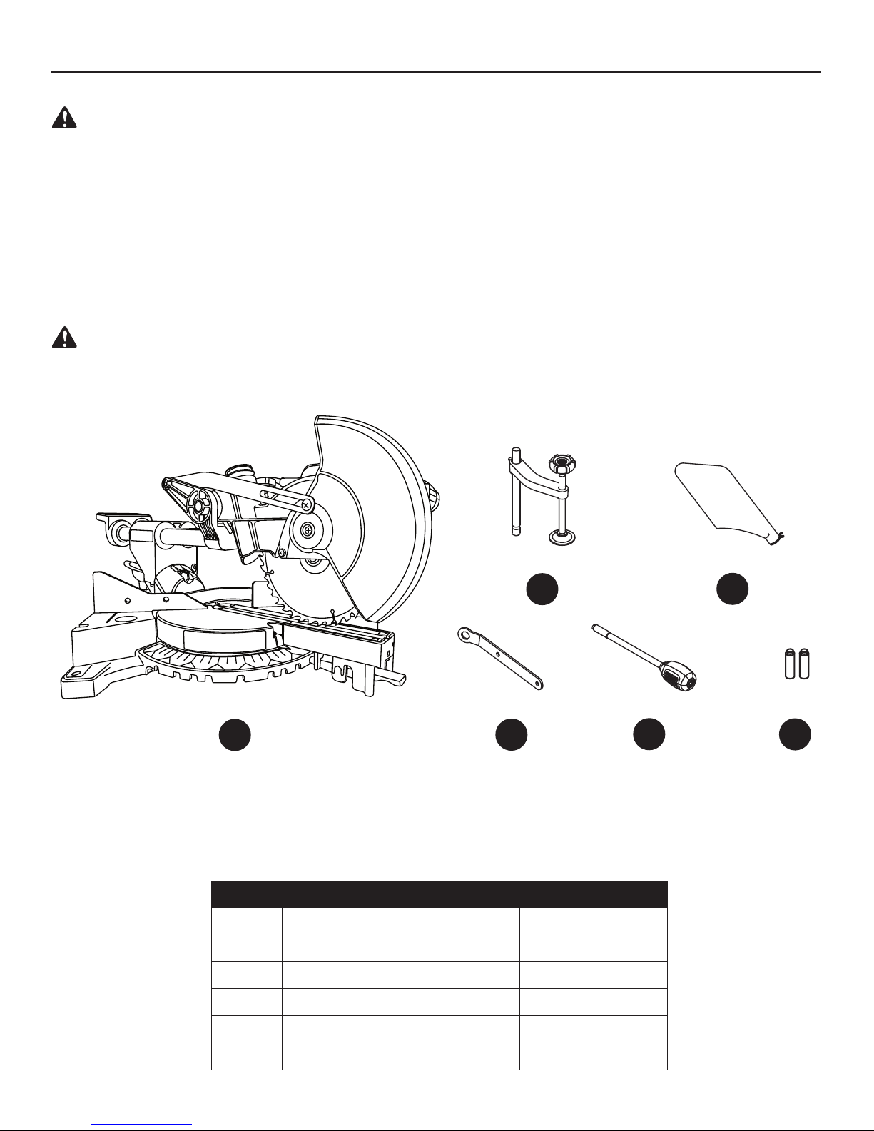
PACKAGE CONTENTS
UNPACKING YOUR MITER SAW
WARNING:
To avoid injury from unexpected starting or electrical shock, do not plug the power cord
into a source of power during unpacking and assembly. The cord must remain unplugged whenever
you are adjusting/assembling the saw.
1. Remove the miter saw from the carton.
IMPORTANT: Do not lift miter saw by the trigger switch handle. It may cause misalignment. Lift the
saw by the hand holds for transportation.
2. Place the saw on a secure, stationary work surface.
3. Separate all parts from the packing material. Check each one with the illustration below to make
certain all items are accounted for before discarding any packing material.
WARNING:
If any part is missing or damaged, do not attempt to assemble the miter saw or plug
in the power cord until the missing or damaged part is correctly replaced. To avoid electric shock,
use only identical replacement parts when servicing double-insulated tools.
B
A
D
PART DESCRIPTION QUANTITY
A Miter saw 1
B Hold-down clamp 1
C Dust bag 1
E
C
F
D Blade wrench 1
E Miter handle 1
F AAA battery 2
3
Page 4

SAFETY INFORMATION
GENERAL SAFETY INFORMATION
PROPOSITION 65 WARNING
Some dust created by power sanding, sawing, grinding, drilling and other construction activities contains
chemicals known to the State of California to cause cancer, birth defects or other reproductive harm.
Some examples of these chemicals are:
● Lead from lead-based paints,
● Crystalline silica from bricks and cement and other masonry products, and
● Arsenic and chromium from chemically-treated lumber.
Your risk from these exposures varies depending on how often you do this type of work. To reduce
your exposure to these chemicals: work in a well ventilated area and work with approved safety
equipment, such as dust masks that are specially designed to filter out microscopic particles.
Handling the power cord on this product may expose you to chemicals known to the State of
California to cause cancer and birth defects or other reproductive harm. Wash hands after handling.
CAUTION
● Use only the accessories recommended for this miter saw. Follow instructions that accompany the
accessories. Use of improper accessories may cause injury.
● The use of any cutting tool except 7-1/4 in. saw blades is prohibited. Do not use accessories such
as shaper cutters or dado sets. Ferrous metal cutting, the use of abrasive wheels and the cutting
of masonry products are prohibited.
● D
o not attempt to modify this tool or create accessories not recommended for use with this tool. Any
such alteration or modification is misuse and could result in a hazardous condition leading to possible
serious injury.
WARNING
To avoid the risk of personal injury, do not modify this power tool or use accessories not recommended
to fit your tool.
WARNING
Read warnings and conditions on your CARBIDE TIPPED SAW BLADE.
● Do not operate the saw without the proper saw blade guard in place.
● Carbide is a very hard but brittle material. Care should be taken while mounting, using and storing
carbide tipped blades to prevent accidental damage.
● Slight shocks, such as striking the tip, can seriously damage the blade. Foreign objects in the
workpiece, such as wire or nails, can also cause tips to crack or break off.
● Before using, always visually examine the blade and tips for bent teeth, cracks, breakage, missing
or loose tips, or other damage.
● Do not use if damage is suspected. Failure to heed safety instructions and warnings can result in
serious bodily injury or loss of eyesight.
4
Page 5

SAFETY INFORMATION
POWER TOOL SAFETY
Please read and understand this entire manual before attempting to assemble, operate or install the
product. These safety instructions are not meant to cover every possible condition that could occur.
GENERAL SAFETY INSTRUCTIONS
● LEARN the tool’s application, limitations and possible hazards.
● KEEP GUARDS IN PLACE and in working order.
● REMOVE ADJUSTING KEYS AND WRENCHES. Always check to see that keys and adjusting
wrenches are removed from the tool and properly stored before turning it ON.
● KEEP WORK AREA CLEAN. Cluttered areas and benches invite accidents.
● DO NOT USE IN DANGEROUS ENVIRONMENTS. Do not use power tools in damp locations or
expose them to rain or snow. Keep work area well lit.
● KEEP CHILDREN AWAY. All visitors and bystanders should be kept at a safe distance from work
area.
● MAKE WORKSHOP CHILDPROOF with padlocks, master switches or by removing starter keys.
● DO NOT FORCE THE TOOL. It will do the job better and is safer if used at the rate for which it
was designed.
● USE THE RIGHT TOOL. Do not force the tool or an attachment to do a job for which it was not
designed.
● USE PROPER EXTENSION CORDS. Make sure your extension cord is in good condition. When
using an extension cord, be sure to use one heavy enough to carry the current your product will
draw. An undersized cord will result in a drop in line voltage and in loss of power that will cause the
tool to overheat. The table on page 9 shows the correct size to use depending on cord length and
nameplate ampere rating.
● WEAR PROPER APPAREL. Do not wear loose clothing, gloves, neckties, rings, bracelets or other
jewelry that may get caught in moving parts. Non-slip footwear is recommended. Contain long hair.
● ALWAYS WEAR EYE PROTECTION. Any power tool can throw foreign objects into the eyes and
could cause permanent eye damage. ALWAYS wear safety goggles (not glasses) that comply with
ANSI Safety standard Z87.1. Everyday eyeglasses have only impact-resistant lenses. They ARE
NOT safety glasses. NOTE: Wearing glasses or goggles not in compliance with ANSI Z87.1 could
lead to serious injury.
● WEAR A FACE MASK OR DUST MASK AND WEAR HEARING PROTECTION. Operating power
tools produces sawdust. Use a dust mask in dusty work conditions. Wear hearing protection during
extended periods of operation.
● SECURE WORK. Use clamps or a vise to hold work when practical. It is safer than using your
hand and it frees both hands to operate the tool.
● DISCONNECT TOOLS FROM POWER SOURCE before servicing and when changing
accessories, such as blades, bits and cutters.
● REDUCE THE RISK OF UNINTENTIONAL STARTING. Make sure switch is in the OFF position
before plugging in the tool.
● USE RECOMMENDED ACCESSORIES. Consult this Operator’s Manual for recommended
accessories. The use of improper accessories may lead to risk of injury to yourself or others.
● NEVER STAND ON THE TOOL. Serious injury could occur if the tool is tipped or if the cutting tool
is unintentionally contacted.
● CHECK FOR DAMAGED PARTS. Check the tool for alignment of moving parts, binding of moving
parts, breakage of parts or mounting and any other conditions that may affect its operation.
Damaged parts should be properly repaired or replaced.
● NEVER LEAVE THE TOOL RUNNING UNATTENDED. TURN THE POWER OFF. Do not walk
away from a running tool until the blade comes to a complete stop. Unplug the unit.
● DO NOT OVERREACH. Keep proper footing and balance at all times.
5
Page 6

● MAINTAIN TOOLS WITH CARE. Keep tools sharp and clean for best and safest performance.
Follow instructions for lubricating and changing accessories.
● DIRECTION OF FEED. Feed work into a blade or cutter against the direction of rotation of the
blade or cutter.
CAUTION: Dust generated from certain materials can be hazardous to your health. Always
operate the saw in a well-ventilated area and provide for proper dust removal.
WARNING: People with electronic devices, such as pacemakers, should consult their
physician(s) before using this product. Operation of electrical equipment in close proximity to a
heart pacemaker could cause interference or failure of the pacemaker.
COMPOUND MITER SAW SAFETY
● USE ONLY CROSS-CUTTING OR COMBINATION SAW BLADES. IMPORTANT: The improper
blades may deflect and contact the blade guard and will cause possible injury to the operator.
● DO NOT operate the miter saw until it is completely assembled and installed according to these
instructions.
● IF YOU ARE NOT thoroughly familiar with the operation of a miter saw, seek guidance from your
supervisor, instructor or other qualified person.
● ALWAYS hold the work firmly against the fence and table. DO NOT perform any operation free
hand. Use clamp whenever possible.
● KEEP HANDS out of the path of the saw blade. If the workpiece you are cutting would cause your
hands to be within “no-hands zone” area of the saw blade, the workpiece should be clamped in
place before making the cut.
● MAKE SURE the blade is sharp, runs freely and is free of vibration.
● ALLOW the motor to come up to full speed before starting a cut.
● KEEP THE MOTOR AIR SLOTS CLEAN and free of chips or dust.
● ALWAYS MAKE SURE all handles are tight before cutting, even if the table is positioned in one of
the positive stops.
● MAKE SURE both the blade and the collar are clean and the arbor bolt is tightened securely.
● USE only blade collars specified for your saw.
● NEVER use blades larger than 7-1/4 in. diameter.
● NEVER apply lubricants to the blade when it is running.
● ALWAYS check the blade for cracks or damage before operation. Replace a cracked or damaged
blade immediately.
● NEVER use blades recommended for operation at less than 5,000 RPM.
● ALWAYS keep the blade guards in place and use at all times.
● NEVER reach around the saw blade.
● MAKE SURE the blade is not in contact with the workpiece before the switch is turned ON.
● IMPORTANT: After completing the cut, release the trigger switch and wait for the blade to stop
before returning the saw to the raised position.
● MAKE SURE the blade has come to a complete stop before removing or securing the workpiece,
changing the workpiece angle or changing the angle of the blade.
● NEVER cut metals or masonry products with this tool. This miter saw is designed for use on wood
and wood-like products.
● TO PREVENT severe cuts or injury, clamp all workpieces that can cause your arms, hands or
fingers to move within 6-3/4” of the saw blade.
● PROVIDE adequate support to the sides of the saw table for long workpieces.
● NEVER use the miter saw in an area with flammable liquids or gases.
● NEVER use solvents to clean plastic parts. Solvents could possibly dissolve or otherwise damage
the material.
● SHUT OFF the power before servicing or adjusting the tool.
6
Page 7

● DISCONNECT the saw from the power source and clean the machine when finished using.
● SHOULD any part of your miter saw become missing, damaged, fail in any way or any electrical
component fail to perform properly, shut off the switch and remove the plug from the power supply
outlet. Replace missing, damaged or failed parts before resuming operation.
● Because of the downward cutting motion, your safety requires that you stay very alert to keeping
hands and fingers away from the path that the blade travels.
● Be sure all guards are in place and working. If a guard seems slow to return to its normal position
or “hangs up,” adjust or repair it immediately. Be alert at all times - especially during repetitive,
monotonous operations. Don’t be lulled into carelessness due to a false sense of security. Blades
are extremely unforgiving. Clean the lower guard frequently to help visibility and movement.
Unplug before adjustment or cleaning.
● Abrasive cut-off wheels should not be used on miter saws. Miter saw guards are not appropriate
for abrasive cut-off wheels.
● To avoid loss of control or placing hands in the path of the blade, hold or clamp all material
securely against the fence when cutting. Do not perform operations freehand.
● Support long material at the same height as the saw table.
● Never place your hands or fingers in the path of the blade, or reach in back of the fence. It’s
hazardous to do so. Do not cross arms or hands in front of blade to secure workpiece. Use clamps
if necessary. Saw blades coast after being turned off. To avoid contact with a coasting blade, do not
reach into cutting areas until the blade comes to a full stop.
● After completing a cut, release the trigger switch and allow the blade to come to a complete stop,
then raise the saw blade from the workpiece.
● Miter saws have spring loaded saw heads to return the saw head to its up position. Adjust, repair,
or replace the spring mechanism if the saw head does not automatically return to its up position
when released.
● Hold or clamp the work firmly against the fence on the sawed end.
● Lock the miter saw and blades in the down position during transport or when not in use.
● DRY RUN - It is important to know where the blade will intersect with the workpiece during cutting
operations.
● Always perform the simulated cutting sequence with the power tool switched OFF to gain an
understanding of the projected path of the saw blade.
WARNING: Additional warnings are listed throughout this manual. Please review all
before operating this power tool.
7
Page 8
SAFETY INFORMATION
ELECTRICAL SPECIFICATIONS AND SAFETY
CAUTION: POWER SUPPLY AND MOTOR
The A/C motor used in this saw is a universal, nonreversible type. See “MOTOR” in the
“PRODUCT SPECIFICATIONS” section on page 2.
To avoid electrical hazards, fire hazards or damage to the tool, use proper circuit protection.
Your saw is wired at the factory for 120V operation. Connect to a 120V, 15A circuit and use a 15A
time-delay fuse or circuit breaker. If power cord is worn or cut or damaged in any way, have it
replaced immediately to avoid shock or fire.
DOUBLE INSULATED
This power tool is double insulated to provide a double thickness of insulation between you and the
tool’s electrical system. All exposed metal parts are isolated from the internal metal motor components
with protective insulation.
REPLACEMENT PARTS
– When servicing, use only identical replacement parts. Refer to the
Replacement Parts List on pages 38-43.
POLARIZED PLUGS – To reduce the risk of electrical shock, this saw has a
polarized plug (one blade is wider than the other). This plug (illustrated at right)
will fit in a polarized outlet only one way. If the plug does not fit fully in the outlet,
reverse the plug. If it still does not fit, contact a qualified electrician to install the
proper outlet. Do not change the plug in any way.
CAUTION: Double insulation does not take the place of normal safety precautions when
operating this tool. To avoid electrocution:
● Use only identical replacement parts when servicing a tool with double insulation. Servicing should
be performed by a qualified technician.
● Do not use power tools in wet or damp locations or expose them to rain or snow.
MOTOR SAFETY PROTECTION
CAUTION: To avoid motor damage, the motor should be blown out or vacuumed frequently to
keep sawdust from interfering with motor ventilation.
● CONNECT this saw to a 120V circuit. This circuit must not be less than a #18 wire with a 9A time
lag fuse.
NOTE: When using an extension cord on a circuit with a #18 wire, the extension cord must not exceed
25 feet in length.
● If the motor will not start, release the trigger switch immediately. UNPLUG THE SAW. Check the
saw blade to make sure it turns freely. If the blade is free, try to start the saw again. If the motor
still does not start, refer to TROUBLESHOOTING.
● If the tool suddenly stalls while cutting wood, release the trigger switch, unplug the tool and free
the blade from the wood. The saw may now be started and the cut finished.
● FUSES may “blow” or circuit breakers may trip frequently if:
- MOTOR is overloaded – overloading can occur if you feed too rapidly or make too many
starts/stops in a short time.
- LINE VOLTAGE is more than 10% above or below the nameplate voltage rating. For heavy
loads, the voltage at motor terminals must equal the voltage specified on the nameplate.
- IMPROPER or dull saw blades are used.
8
Page 9

GUIDELINES FOR EXTENSION CORDS
When using an extension cord, be sure to use one heavy enough to carry the current your
product will draw. An undersized cord will cause a drop in line voltage, resulting in loss of power
and overheating. The table below shows the correct size to use depending on cord length and
nameplate ampere rating. If in doubt, use the next heavier gauge. The smaller the gauge number,
the heavier the cord.
MINIMUM GAUGE FOR EXTENSION CORDS (AWG)
(When using 120 volts only)
Ampere Rating Total length of Cord
More Than Not More Than 25 ft. 50 ft. 100 ft. 150 ft.
0 6 18 16 16 14
6 10 18 16 14 12
10 12 16 16 14 12
12 16 14 12
Not Recommended
Be sure your extension cord is properly wired and in good condition. Always replace a damaged
extension cord or have it repaired by a qualified person before using it. Protect your extension cords
from sharp objects, excessive heat and damp or wet areas.
Use a separate electrical circuit for your tools. This circuit must not be less than #12 wire and
should be protected with a 15A time-delay fuse. Before connecting the tool to the extension cord,
make sure the saw switch is in the OFF position. The electric circuit should be rated at the same
voltage as is stamped on the motor nameplate. Running at a lower voltage will damage the motor.
CAUTION: In all cases make certain the receptacle in question is properly grounded. If you are
not sure, have a certified electrician check the receptacle.
9
Page 10

PREPARATION
Before beginning assembly or operation of the product, make sure all parts are present. Compare
parts with package contents list and diagram on page 3. If any part is missing or damaged, do not
attempt to assemble, install or operate the product.
Estimated Assembly Time: 10 minutes
Tools Required for Assembly (included): Blade Wrench
Tools Required for Assembly (not included): Adjustable Wrench, 2 mm Hex Wrench, 8 mm Hex
Wrench, 10 mm Hex Wrench, Combination Square, Phillips Screwdriver, Flathead Screwdriver.
10
Page 11
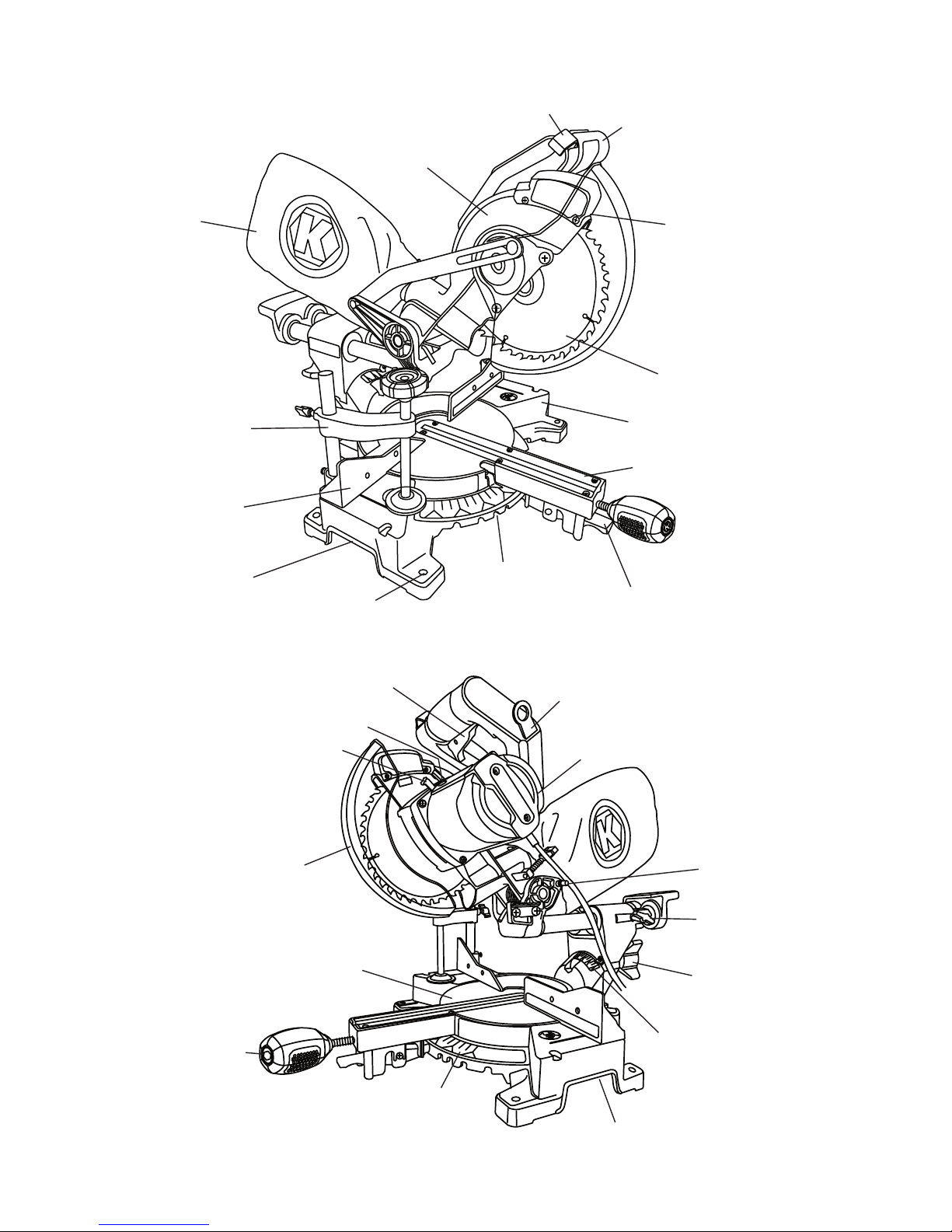
KNOW YOUR MITER SAW
K
Dust Bag
Hold-Down Clamp
Fence
Safety Lock
Switch Handle
Upper Blade
Guard
Laser Guide
Blade
Base
Table Insert
Hand Hold for
Transportation
Arbor Lock Button
Lower Blade
Guard
Mounting Hole
ON/OFF Trigger Switch
Motor Brush
Table
Positive Miter Stop
Positive Miter Stop
Locking Lever
Blade Wrench
Motor
Head Hold-Down
Latch
Sliding Carriage
Lock Knob
Bevel Locking
Handle
Miter Handle
Miter
Scale
Bevel Scale
Hand Hold for
Transportation
11
Page 12
ASSEMBLY INSTRUCTIONS
WARNING: To avoid injury, do not connect this
miter saw to a power source until it is completely
assembled and adjusted and you have read and
understood the operator’s manual.
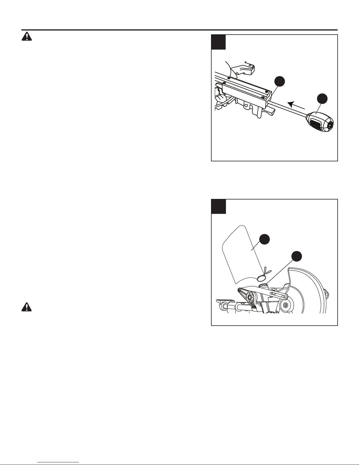
INSTALLING THE MITER HANDLE (FIG. 1)
● Thread the miter handle (E) into the hole located
at the front of the miter saw (A).
INSTALLING THE DUST BAG (FIG. 2)
●
Squeeze the metal collar wings on the dust bag (C).
●
Place the dust bag neck opening around the
exhaust port on the miter saw (A) and release the
metal collar wings.
1
A
E
2
C
NOTE: To empty the dust bag, squeeze the metal collar
wings and remove from exhaust port. Open zipper on
underside of bag and empty into waste container.
IMPORTANT: Check frequently and empty bag before
it gets full.
WARNING: Do not use this saw to cut and/or sand
metals. The hot chips or sparks may ignite sawdust
from the bag material.
A
12
Page 13
INSTALLING THE HOLD-DOWN CLAMP (FIG. 3)
AAABattery
AAA Battery
LASER
ON
OFF
NOTE: There are two mounting holes for the holddown clamp. These are located just behind the fence
on the left and right side of the base.
3
● Loosen the screw with a Phillips screwdriver.
● Place the hold-down clamp (B) in the desired
mounting hole.
● Tighten the screw to hold the hold-down
clamp.
SAW BLADE WRENCH (FIG. 4)
For convenient storage and prevention of loss, there
is a slot in the side of the switch handle for storing the
blade wrench (D) when not in use.
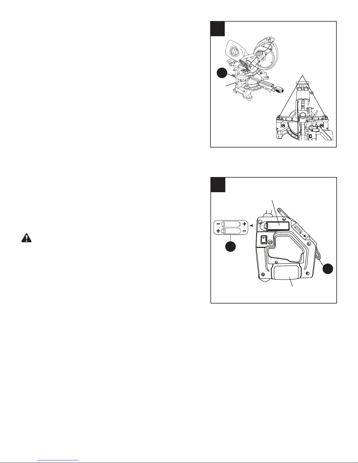
INSERTING AND REPLACING BATTERIES FOR
THE LASER (FIG. 4)
• Unplug your miter saw.
B
Screw
4
Mounting holes
Battery cover
WARNING:
Failure to unplug your tool could
result in accidental starting causing possible
serious personal injury.
● Open the battery cover located on the switch
handle.
● Insert the two supplied AAA batteries (F) as per
the diagram. If replacing the batteries, take out the
old batteries and replace with new AAA batteries.
Dispose of old batteries properly.
● Close the battery cover.
NOTE: Replace with batteries that have a rating of
1.5 volts (Number 4 series and AAA size or equivalent).
HELPFUL HINT:
Remove the two batteries during
long periods of non-use of the saw. This will reduce
damage to the laser guide from the batteries
corroding during storage.
F
D
Switch handle
13
Page 14
K
O
B
A
L
T
ADJUSTMENT INSTRUCTIONS
K
K
O
B
A
L
T
UNLOCKING THE SLIDE CARRIAGE (FIG. 5)
● After removing the saw from the carton, loosen
the slide carriage lock knob (1). When transporting
or storing the miter saw, the slide carriage should
always be locked in position. The slide carriage
lock knob (1) is located on the right side of the
slide carriage.
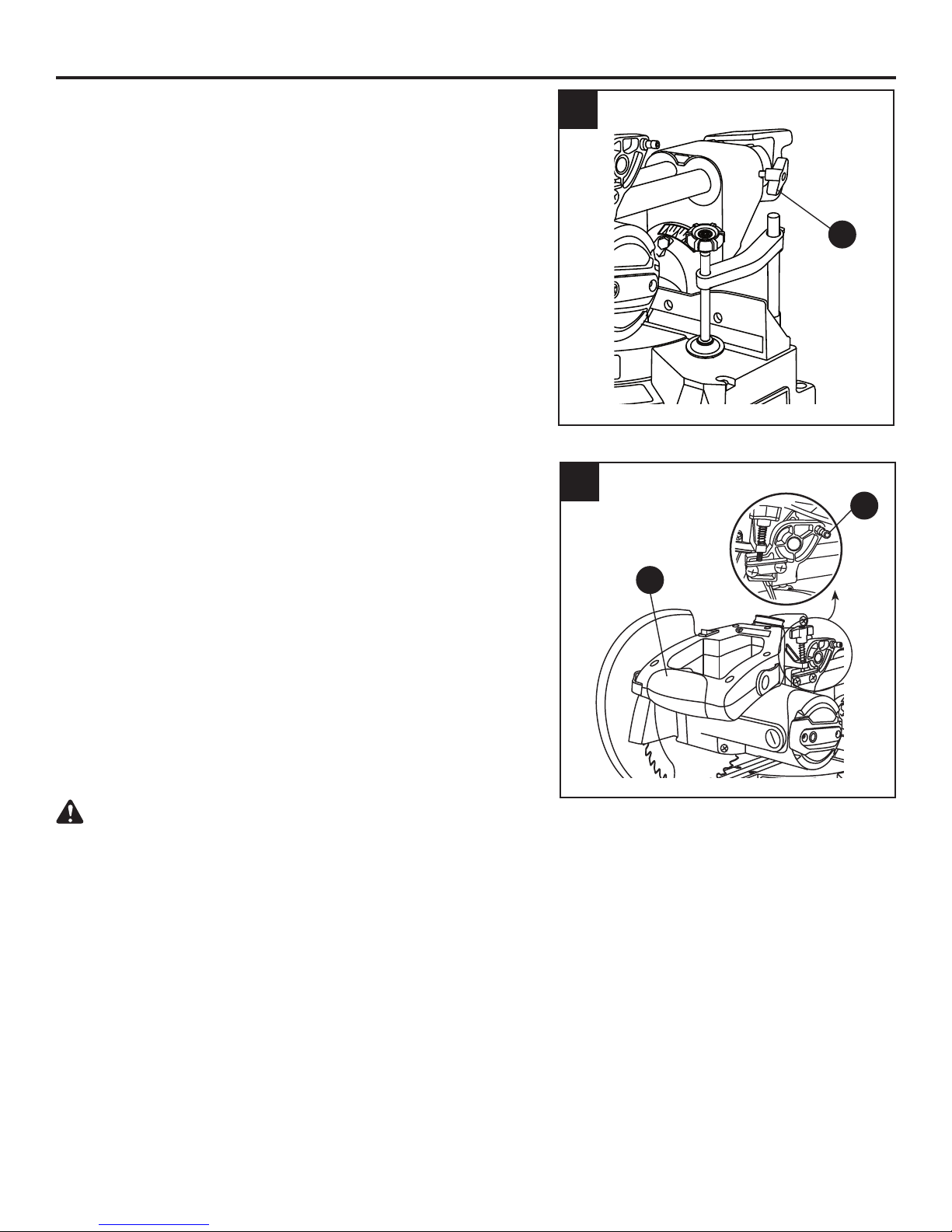
UNLOCKING AND LOCKING THE CUTTER HEAD
(FIG. 6)
Unlocking the cutter head:
●
To raise the cutter head from its storage/transport
position: push down slightly on the switch handle (1).
● Pull out the stop latch knob (2).
● Allow the cutting head to rise to the up position.
5
1
6
2
1
Locking the cutting head:
When transporting or storing the miter saw, the
cutting head should always be locked in the down
position.
● Push the cutting head down to its lowest position.
● Push the stop latch knob (2) into the locking hole.
CAUTION: To avoid injury and damage to the
saw, transport and store the miter saw with the
cutting head locked in the down position. Never
use the stop latch to hold the cutting head in a
down position for cutting operations.
IMPORTANT: To avoid damage, never carry the
miter saw by the switch handle, the cutting arm or the
miter table handle. ALWAYS use the hand holds for
transportation.
14
Page 15

REMOVING AND INSTALLING THE TABLE INSERT
(FIG. 7)
NOTE: The miter saw comes with the table inserts
already installed. These instructions are for replacing
or adjusting either insert side.
WARNING
To avoid injury:
● Always unplug the saw to avoid accidental
starting. Remove all small pieces of material from
the table cavity before performing any cuts. The
table insert may be removed for this purpose, but
always reattach the table insert prior to performing
a cutting operation.
● Do not start the sliding compound miter saw
without checking for interference between the
blade and table insert. Damage could result to
blade, table insert or turntable if blade strike occurs
during the cutting operation.
●
To remove, loosen and remove the six screws (1)
on the table insert (2) with a Phillips screwdriver and
remove the insert.
● To install, reposition the table insert, install the six
screws and tighten.
●
Check for blade clearance by moving the slide carriage
through the full motion of the blade in the table slot. If
neither side of the insert hits the saw blade, loosen the
three screws for that side and adjust. Tighten the screws
and check again for blade clearance.
the
7
1
2
15
Page 16

MOUNTING THE MITER SAW (FIG. 8, 9, 10)
WARNING
To avoid injury from unexpected saw movement:
● Disconnect the power cord from the outlet and
lock the cutting head in the lower position using
the stop latch.
● Lock the slide carriage in place by tightening the
slide carriage lock knob.
● To avoid back injury, lift the saw by using the hand
holds for transportation. Bend with your knees, not
your back.
● Never carry the miter saw by the power cord or by
the switch handle. Carrying the tool by the power
cord could cause damage to the insulation or the
wire connections resulting in electric shock or fire.
● To avoid injury from flying debris, do not allow
visitors to stand near the saw during any cutting
operations.
Mounting instructions:
● For stationary use, place the saw in the desired
location, directly on a workbench where there
is room for handling and proper support of the
workpiece. The base of the saw has four mounting
holes (10) (Fig. 8). Bolt the base of the miter saw
(1) to the work surface (5), using the recommended
fastening method as shown in Fig. 9.
NOTE: Mounting hardware is not included with
this tool. Bolts, nuts, washers and screws must be
purchased separately.
● For portable use, place the saw on a 3/4 in. thick
piece of plywood. Bolt the base of the miter saw
securely to the plywood using the mounting holes
(10) (Fig. 8) on the base. Use C-clamps to clamp
this mounting board to a stable work surface at
the worksite (Fig. 10).
8
10
9
1. Miter saw base
2. Hex head bolt
3. Rubber washer
4. Flat washer
5. Work surface
6. Flat washer
7. Lockwasher
8. Hex/Lock nut
9. Jam nut
10
Stationary Use
Portable Use
10
1010
2
3
4
1
5
6
7
8
9
NOTE: If a miter saw stand is used, please follow all
instructions shown in that product’s instructions for
proper mounting.
3/4 in.
plywood
16
Page 17

REMOVING AND INSTALLING THE BLADE
WARNING:
To avoid injury from an accidental start, make
sure the switch is in the OFF position and the
plug is not connected to the power source outlet.
REMOVING (FIG. 11, 12, 13)
● Unplug the saw from the outlet.
● Allow the miter saw cutting head to rise to the
upright position. Raise the lower blade guard (1)
to the up position.
● Loosen the cover plate screw (2) with a Phillips
screwdriver.
NOTE: Do not remove this screw.
● Rotate the cover plate (3) upward to expose the
arbor bolt (4).
● Place the blade wrench over the arbor bolt.
● Locate the arbor lock button (5) on the front of the
motor, below the miter saw switch handle (Fig. 12).
● Press the arbor lock button, holding it in firmly
while turning the blade wrench clockwise. The
arbor lock will engage after turning the wrench.
Continue to hold the arbor lock button to keep it
engaged, while turning the wrench clockwise to
loosen the arbor bolt.
● Remove the arbor bolt (4), the blade collar (6) and
the blade (7). Do not remove the inner blade collar
(Fig. 13).
NOTE: Pay attention to the pieces removed, noting
their position and direction they face. Wipe the blade
collar clean of any sawdust before installing a new
blade.
Only use a 7-1/4 in. diameter blade.
11
1
3
2
4
12
5
17
Page 18

INSTALLING BLADE (FIG. 11, 12, 13
Unplug the miter saw before changing/installing
the blade.
● Install a 7-1/4 in. blade with a 5/8 in. arbor,
making sure the rotation arrow on the blade
matches the clockwise rotation arrow on the
upper guard.
● Place the blade collar (6) against the blade
and on the arbor. Thread the arbor bolt (4)
onto the arbor (Fig. 13) in a counterclockwise
direction.
IMPORTANT: Make sure the flats of the
blade collars are engaged with the flats on
the arbor shaft. Also, the flat side of the blade
collar must be placed against the blade.
● Place the blade wrench on the arbor bolt.
● Press the arbor lock button (5), holding
it in firmly while turning the blade
counterclockwise. When arbor lock engages,
continue to press it in while tightening the
arbor bolt securely (Fig. 12).
● Rotate the cover plate (3) back to its original
position until the slot in the cover plate
engages with the cover plate screw (2). While
holding the lower blade guard, tighten the
screw with a Phillips screwdriver (Fig. 11).
NOTE: The lower blade guard must be raised
to the upright position to access the cover
plate screw.
●
Lower the blade guard (1) and verify that the
operation of the guard does not bind or stick
(Fig. 11).
● Be sure the arbor lock is released so the
blade turns freely before operating the saw.
)
13
7
6
4
WARNING
● To avoid injury, never use the saw without the cover plate securely in place. It keeps the arbor
bolt from falling out if it accidentally loosens and helps prevent the spinning blade from coming
off the saw.
● Make sure the collars are clean and properly arranged. Lower the blade into the lower table and
check for any contact with the metal base or the miter table.
● To avoid injury from an accidental start, make sure the switch is in the OFF position and the plug
is not connected to the power source outlet.
● Never cut metals or masonry products with this tool. This miter saw is designed for use on wood
and wood-like products only.
18
Page 19

BEVEL STOP ADJUSTMENT (FIG. 14, 15, 16)
K
WARNING:
To avoid injury from an accidental start,
make sure the switch is in the OFF position and the
plug is not connected to the power source outlet.
14
1
3
90° (0°) Bevel Adjustment (FIG. 14):
●
Loosen bevel lock handle (1) and tilt the cutting arm
completely to the right. Tighten the bevel lock handle.
● Place a combination square (2) on the miter table
with the ruler against the table and the heel of the
square against the saw blade.
● If the blade is not 90° square with the miter table (5),
loosen the bevel lock handle (1), tilt the cutting head
to the left, loosen the locknut (4) and turn the bevel
angle adjustment bolt (3) in or out with a 10 mm
wrench until the blade is square with the table.
● Tilt the cutting arm back to the right at 90° (0°)
bevel and recheck for alignment.
● Repeat steps 1 through 4 if further adjustment
is needed.
● Tighten bevel lock handle and locknut (4) when
alignment is achieved.
90° Bevel Pointer Adjustment (FIG. 15):
● When the blade is exactly 90° to the table, loosen
the bevel indicator screw (1) using a Phillips
screwdriver.
● Adjust bevel indicator (2) to the “0” mark on the
bevel scale and retighten the screw.
15
4
2
5
1
2
WARNING: To avoid injury from an accidental
start, make sure the switch is in the OFF position
and the plug is not connected to the power
source outlet.
45° Bevel Adjustment (FIG. 16):
● Loosen the bevel lock handle (1) and tilt the
cutting head completely to the left.
● Using a combination square, check to see if the
blade angle is 45° to the table.
● If the blade is not at 45° to the miter table, tilt the
cutting arm to the right, loosen the locknut (2) on
the bevel angle adjustment bolt (3) and use a
10 mm wrench to the adjustment bolt (3) depth in
or out to increase or decrease the bevel angle.
●
Tilt the cutting arm to the left to 45° bevel and
recheck for alignment.
● Repeat steps 1 through 4 until the blade is at 45° to
the miter table.
● Tighten bevel lock handle (1) and locknut (2) when
alignment is achieved.
19
16
1
3
2
Page 20

MITER SCALE (FIG. 17)
The sliding compound miter saw scale can be easily
read, showing miter angles from 0° to 45° to the left,
and 0° to 45° to the right. The miter saw table has
nine of the most common angle settings with positive
stops at 0°, 15°, 22.5°, 31.6°, and 45°. These positive
stops position the blade at the desired angle quickly
and accurately. Follow the process below for quickest
and most accurate adjustments.
To Adjust Miter Angles:
● Unlock the miter table by turning the miter handle
(1) counterclockwise.
● Move the turntable while lifting up on the positive
stop locking lever (2) to align the indicator (3) to
the desired degree measurement.
● If the desired angle is one of the nine positive
stops, release the positive stop locking lever,
making sure the lever snaps into position, and then
secure by tightening the miter handle.
● If the miter angle desired is not one of the nine
positive stops, simply lock the miter table into
desired angle position by turning the miter handle
in the clockwise direction.
17
1
4
3
2
Miter Angle Pointer Adjustment (FIG. 17)
● Move the table to the 0° positive stop.
● Loosen the screw (4) that holds the indicator with
a Phillips screwdriver.
● Adjust the indicator (3) to the 0° mark and
retighten the screw.
ADJUSTING FENCE SQUARENESS (FIG. 18)
● Lower the cutting arm and lock in position.
● Using a square (3), lay the heel of the square
against the blade and the ruler against the fence
(2) as shown.
● Loosen the two fence locking bolts (1) with an 8 mm
hex wrench.
● Adjust the fence 90° to the blade and tighten the
four fence locking bolts.
NOTE: If the saw has not been used recently,
recheck blade squareness to the fence and
readjust if needed.
●
After fence has been aligned, make a cut at 90°
using a scrap piece of wood and check squareness
on the piece. Readjust if necessary.
18
1
2
3
1
20
Page 21

LASER
ON
OFF
SETTING CUTTING DEPTH (FIG. 19)
The depth of cut can be preset for even and repetitive
shallow cuts.
● Adjust the cutting head down until the teeth of the
blade are at the desired depth.
●
While holding the upper arm in that position, turn
the stop knob (1) until it touches the stop plate (2).
● Recheck the blade depth by moving the cutting
head front to back through the full motion of a
typical cut along the control arm.
MAXIMUM CUTTING DEPTH (FIG. 19)
The maximum depth travel of the cutting head was
set at the factory. Check to see that the blade does
not extend more than 1/4 in. below the table insert,
and does not touch the control arm throat or any part
of the base or table. If the maximum depth needs
readjusting:
● Loosen the bolts of the stop plate (2).
● Move the cutting head down until the blade
extends just 1/4 in. below the table insert.
● Adjust the stop place to touch the bottom of the
stop knob (1) when the stop knob is raised fully.
● Recheck the blade depth by moving the cutting
head front to back through the full motion of a cut
along the control arm. If the blade touches the
inside of the control arm, readjust the setting.
19
1
2
THE LASER GUIDE (FIG. 20, 21)
20
WARNING
For your own safety, never connect the plug to a
power source outlet until all the adjustment steps
are complete and you have read and understood
the safety and operational instructions.
Your tool is equipped with a laser guide using a Class
IIIa laser beam. The laser beam will enable you to
preview the saw blade path on the workpiece to be
cut before starting the miter saw. This laser guide is
powered by two AAA 1.5 volt batteries.
● To turn laser on, press on/off rocker switch (1)
to “ON” position.
●
To turn laser off, press on/off rocker switch to
“OFF” position.
1
21
Page 22

DANGER:
:
Puissance
Ce produit est conforme aux normes 21CFR 1040.10 et 1040.11
à
M
las normas
AVOID DIRECT EYE CONTACT
● A red laser line is radiated when the laser guide
switch is turned on. Avoid direct eye contact.
Always unplug the miter saw from power source
before making any adjustments.
● Laser Warning Label: Max. output < 5 mW,
wavelength: 630-660 nm, complies with 21CFR
1040.10 and 1040.11 Class IIIa laser product.
(Fig. 21)
● Laser Aperture Label:
AVOID EXPOSURE:
Laser radiation is emitted from this aperture.
(Fig. 21)
NOTE:
● All the adjustments for the operation of this laser
guide have been completed at the factory. Laser
guide is calibrated and set up to project to the
right of the blade (Fig. 22).
21
Laser warning
label
Laser aperture
label
WARNING
● Use of controls or adjustments or performance of
procedures other than those specified herein may
result in hazardous radiation exposure.
WARNING
● The use of optical instruments with this product
will increase eye hazard.
● Do not attempt to repair or disassemble the
laser. If unqualified persons attempt to repair
this laser product, serious injury may result. Any
repair required on this laser product should be
performed by authorized service center personnel.
22
Workpiece
Blade
Laser beam
Cutting line
Laser beam
Cutting line
TOP VIEW
22
Page 23

OPERATING INSTRUCTIONS
BEFORE USING THE MITER SAW
WARNING:
To avoid mistakes that could cause serious, permanent injury, do not plug the tool in
until the following steps are completed:
● Completely assemble and adjust the saw, following the instructions (SEE ASSEMBLY AND
ADJUSTMENTS SECTIONS).
● Learn the use and function of the ON/OFF switch, upper and lower blade guards, stop latch, bevel
lock handle and cover plate screws.
● Review and understand all safety instructions and operating procedures in this Operator’s Manual
(SEE SAFETY & OPERATIONS SECTIONS).
● Review the MAINTENANCE and TROUBLESHOOTING for your miter saw.
● To avoid injury or possible death from electrical shock, make sure your fingers do not touch the plug’s
metal prongs when plugging or unplugging your miter saw (SEE ELECTRICAL REQUIREMENTS
AND SAFETY SECTIONS).
BEFORE EACH USE
Inspect your saw.
● Disconnect the miter saw. To avoid injury from accidental starting, unplug the saw before making
any adjustments, including setup and blade changes.
● Compare the direction of rotation arrow on the guard to the direction arrow on the blade. The blade
teeth should always point downward at the front of the saw.
● Tighten the arbor bolt.
● Tighten the cover plate screw.
● Check for damaged parts, including:
- Alignment of moving parts
- Damaged blade teeth
- Damaged electric cords
- Binding of moving parts
- Mounting holes
● Function of arm return spring and lower guard: Push the cutting arm all the way down and
then let it rise until it stops. The lower guard should close fully. Follow the instructions in the
Troubleshooting for adjustment, if necessary.
● Keep all guards in place, in working order and properly adjusted. If any part of this miter saw is
missing, damaged or broken, or any electrical parts do not work, turn off the saw and unplug it.
Replace damaged, missing or defective parts before using the saw again.
● Maintain tools with care. Keep the miter saw clean for best and safest performance. Follow
instructions for lubricating. Do not apply lubricants to the blade while it is spinning.
● Remove all adjusting wrenches from the tool before turning it on.
USE ONLY THE RECOMMENDED ACCESSORIES
● Follow the instructions that come with the accessory. The use of improper accessories may cause
risk of injury to persons.
● Choose the correct 7-1/4 in. blade for the material and the type of cutting you plan to do.
● Make sure the blade is sharp, undamaged and properly aligned. With the saw unplugged, push the
cutting arm all the way down. Manually spin the blade and check for clearance. Tilt the miter head
to a 45° bevel and repeat the test.
● Make sure the blade and arbor collars are clean.
● Make sure all clamps and locks are tight and there is no excessive play in any parts.
23
Page 24

KEEP YOUR WORK AREA CLEAN
Cluttered areas and benches invite accidents.
WARNING:
To avoid burns or other fire damage, never use the miter saw near flammable liquids,
vapors or gases.
● Plan ahead to protect your eyes, hands, face and ears.
● Read and understand the operator’s manual and labels affixed to the tool. Learn its application
and limitations as well as the potential hazards specific to this tool. To avoid injury from accidental
contact with moving parts, do not layout, assemble or set up work on the miter saw.
● Avoid accidental starting. Make sure the switch is in the OFF position before plugging the miter
saw into a power outlet.
PLAN YOUR WORK
Use the right tool. Do not force a tool or attachment to do a job it was not designed to do. Use a
different tool for any workpiece that cannot be held in a solidly braced, fixed position.
WARNING
This machine is NOT designed for cutting masonry, masonry products or ferrous metals (steel, iron
and iron-based metals). Use this miter saw to cut only wood and wood by-products. Other materials
may shatter, bind the blade or create other dangers. Remove all nails that may be in the workpiece to
prevent sparking that could cause a fire.
DRESS FOR SAFETY
Any power tool can throw foreign objects into the eyes. This can result in permanent eye damage.
Everyday eyeglasses have only impact resistant lenses and are not safety glasses. Glasses or goggles
not in compliance with ANSI Z87.1 could seriously injure you if they break.
● Do not wear loose clothing, gloves, neckties or jewelry (rings, watches). They can get caught and
draw you into moving parts.
● Wear non-slip footwear.
● Tie back long hair.
● Roll long sleeves above the elbow.
● Noise levels vary widely. To avoid possible hearing damage, wear earplugs when using any
miter saw.
● For dusty operations, wear a dust mask along with safety goggles.
INSPECT YOUR WORKPIECE
● Make sure there are no nails or foreign objects in the part of the workpiece being cut.
● Plan your work to avoid small pieces that may bind or are too small to clamp and hold securely.
● Plan the way you will grasp the workpiece from start to finish. Avoid awkward operations and hand
positions. A sudden slip could cause your fingers or hand to move into the blade.
DO NOT OVERREACH
Keep good footing and balance. Keep your face and body to one side, out of the line of a possible
kickback. NEVER stand in the line of the blade.
24
Page 25

Never cut freehand:
● Brace your workpiece firmly against the fence and table stop so it will not rock or twist during
the cut.
● Make sure there is no debris between the workpiece and the table or fence. Make sure there are
no gaps between the workpiece, fence and table that will let the workpiece shift after it is cut.
● Keep the cut piece free to move sideways after it is cut off. Otherwise, it could get wedged against
the blade and thrown violently.
● Only the workpiece should be on the saw table.
● Secure work. Use clamps or a vise to help hold the work when it is practical.
USE EXTRA CAUTION WITH LARGE OR ODD SHAPED WORKPIECES
● Use extra supports (tables, sawhorses, blocks, etc.) for workpieces large enough to tip.
● Never use another person as a substitute for a table extension or as an additional support for a
workpiece that is longer or wider than the basic miter saw table, or to help feed, support or pull
the workpiece.
● Do not use this saw to cut small pieces. If the workpiece being cut would cause your hand or
fingers to be within
6-3/4 in. of the saw blade, the workpiece is too small. Keep hands and fingers
out of the “no-hands zone” area marked on the saw table.
● When cutting odd shaped workpieces, plan your work so it will not bind in the blade and cause
possible injury. Moulding, for example, must lie flat or be held by a fixture or jig that will not let it
move when cut.
● Properly support round material such as dowel rods or tubing, which have a tendency to roll when
cut, causing the blade to “bite.”
WARNING:
To avoid injury, follow all applicable safety instructions when cutting non-ferrous
metals:
● Use only saw blades specifically recommended for non-ferrous metal cutting.
● Do not cut metal workpieces that must be hand held. Clamp workpieces securely.
● Cut non-ferrous metals only if you are under the supervision of an experienced person.
WHEN SAW IS RUNNING
WARNING
Do not allow familiarity from frequent use of your miter saw to result in a careless mistake.
A careless fraction of a second is enough to cause severe injury.
Before cutting, if the saw makes an unfamiliar noise or vibrates, stop immediately. Turn the saw OFF.
Unplug the saw. Do not restart until you find and correct the problem.
25
Page 26

BODY AND HAND POSITION (FIG. 23)
WARNING
Never place hands near the cutting area. Proper
positioning of your body and hands when operating
the miter saw will make cutting easier and safer. Keep
children away. Keep all visitors at a safe distance from
the miter saw. Make sure bystanders are clear of the
saw and workpiece. Do not force the saw. It will do the
job better and safer at its designed rate.
WARNING
Operator and all by-standers must wear proper
safety goggles that comply with OSHA/ANSI
requirements Z87.1
23
Starting a cut:
● Place hands at least 6-3/4 in. away from the path
of the blade – out of the “no-hands zone.”
● Hold workpiece firmly against the fence to prevent
movement toward the blade.
● With the power switch OFF, bring the saw blade
down to the workpiece to see the cutting path of
the blade.
● Squeeze trigger switch to start saw.
● Lower blade into workpiece with a firm downward
motion.
Finishing a cut:
● Hold the cutting arm in the down position.
● Release trigger switch and wait for all moving
parts to stop before moving your hands and
raising the cutting arm.
● If the blade doesn’t stop within 10 seconds,
unplug the saw and follow the instructions in
TROUBLESHOOTING.
No hand zone
13-1/2 in.
Before freeing jammed material:
● Release trigger switch.
● Wait for all moving parts to stop.
● Unplug the miter saw.
26
Page 27

BASIC SAW OPERATIONS
K
O
B
A
L
T
LASER
ON
OFF
24
TURNING THE LASER GUIDE ON (FIG. 24)
Press the on/off rocker switch (1) to “ON” position to
activate the laser guide.
TURNING THE SAW ON (FIG. 24)
This miter saw is equipped with an ON/OFF trigger
switch (2). With the safety lock (3) pressed, squeeze
the trigger switch to turn the miter saw ON.
NOTE: Make the ON/OFF switch childproof. Insert
a padlock or chain with a padlock (not included)
through the hole (4) in the trigger switch, locking
the tool’s switch and preventing children and other
unauthorized users from turning the machine on.
When the trigger switch is released, the blade will be
stopped within 10 seconds.
WARNING
● To avoid injury, after completing a cut and
releasing the trigger switch, wait and confirm the
blade has stopped before raising the cutting head.
● To avoid injury, check and tighten the arbor bolt
periodically.
25
4
3
2
1
SLIDING CARRIAGE SYSTEM (FIG. 25)
CAUTION: To reduce the risk of injury, return
carriage to the full rear position after each
crosscut operation.
For chop cutting operations on small workpieces,
●
1
slide the cutting head assembly completely toward
the rear of the unit and tighten the carriage lock
knob (1).
● To cut wide boards up to 8 in., the carriage lock
knob (1) must be loosened to allow the cutting
head to slide freely.
27
Page 28

BEFORE LEAVING THE SAW
K
● Never leave tool running unattended. Turn power
OFF. Wait for all moving parts to stop.
● Make workshop childproof. Lock the shop.
Disconnect master switches. Store tool away from
children and other unqualified users.
26
WARNING:
To avoid injury from materials being
thrown, always unplug the saw to avoid accidental
starting and remove small pieces of material from
the table cavity.
MITER CUT (FIG. 26)
● When a miter cut is required, unlock the miter table
by turning the miter handle (1) counterclockwise.
● While holding the miter handle, lift up on the
positive stop locking lever (2).
Rotate the miter table to the right or left with the
●
miter handle.
When the table is in the desired position, as
●
shown on the miter scale (3), release the positive
stop locking lever and tighten the miter handle.
The table is now locked at the desired angle.
Positive stops are provided at 0°, 15°, 22.5°, 31.6°
and 45°.
IMPORTANT: Always tighten the miter table lock
handle before performing every cutting operation.
3
1
2
BEVEL CUT (FIG. 27)
● When a bevel cut is required, loosen the bevel
lock handle (1) by turning it clockwise.
● Tilt the cutting head to the desired angle, as
shown on the bevel scale (2).
● The blade can be positioned at any angle, from
a 90° straight cut (0° on the scale) to a 45° left
bevel. Tighten the bevel lock handle (1) to lock
the cutting head in position. Positive stops are
provided at 0° and 45°.
27
1
2
28
Page 29

COMPOUND CUT (FIG. 28)
K
K
K
O
B
A
L
T
K
A compound cut is the combination of a miter and a
bevel cut simultaneously.
● Loosen the bevel lock handle (1) and position the
cutting head at the desired bevel position. Lock
the bevel lock handle (1).
Loosen the miter handle (2). Lift up the positive
●
stop locking lever (3) and position the table at the
desired angle. Release the positive stop locking
lever (3) and lock the miter handle (2).
SLIDE CUTTING WIDE BOARDS UP TO 8 IN. WIDE
(FIG. 29)
CAUTION: Always use a work clamp to maintain
control and reduce the risk of workpiece damage and
personal injury.
To avoid injury:
● Let the blade reach full speed before cutting. This
will help reduce the risk of a thrown workpiece.
● Do not make crosscuts by lowering the blade and
pulling the saw head through the wood toward
you. The blade may try to climb up on top of the
workpiece, causing the cutting assembly and
spinning blade to kick back forcefully.
28
29
1
2
3
4
1
To Slide Cut Wide Boards (FIG. 29)
Unlock the carriage lock handle (1) and allow the
●
2
cutting head assembly to move freely.
●
Set both the desired bevel angle and/or the miter
angle and lock into position.
Use a hold down clamp (2) to secure the
●
3
workpiece (3).
Grasp and pull the switch handle (4) forward until
●
the center of the saw blade is over the front of the
workpiece (3).
Engage the trigger to turn the saw on.
●
When the saw reaches full speed, slowly push the
●
30
switch handle down, cutting through the leading
edge of the workpiece.
● Slowly move the switch handle toward the fence,
completing the cut.
● Release the trigger and allow the blade to stop
spinning before raising the cutting head and
removing the workpiece.
CUTTING BOWED MATERIAL (FIG. 30)
1
A bowed workpiece must be positioned against the fence
and secured with a clamp (1) before cutting as shown.
Do not position workpiece incorrectly or try to cut the
workpiece without the support of the fence. This will cause
the blade to bind and could result in personal injury.
29
Page 30

CUTTING GROOVES (FIG. 31)
K
K
K
O
B
A
L
T
WARNING:
DO NOT USE A DADO BLADE, use
only the standard saw blade for this operation.
● Mark lines to identify the width and depth of
the desired cut on the workpiece and put the
workpiece on the table and aim the inside tip of
the blade at the line. Use a clamp to secure the
workpiece on the table.
● Lower the cutting head so the tip of the blade
touches the top surface of the workpiece at the
marked line.
● While holding the upper arm in position, turn the
stop knob (2) until it touches the stop plate (1).
(SEE “SETTING CUTTING DEPTH” on page 21).
Cut two parallel grooves as shown.
●
31
2
Cut these
grooves
with saw
1
Use a chisel
to cut out the
middle
WORKPIECE SUPPORT (FIG. 32)
Long pieces need extra support. The support should
be placed under the workpiece. Keep your hand
holding the workpiece positioned 6-3/4 inches or
more away from the blade. The support must let
the workpiece lay flat on the work table during the
cutting operation.
NOTE: When mounted on a flat surface, the saw
table is 2-5/8 inches high.
AUXILIARY WOOD FENCE (FIG. 33)
When making multiple or repetitive cuts that result in
cut-off pieces of one inch or less, it is possible for
the saw blade to catch the cut-off piece and throw it
out of the saw or into the blade guard and housing,
possibly causing damage or injury. To minimize this,
an auxiliary wood fence can be mounted to your saw.
Holes are provided in the saw fence to attach an
auxiliary wood fence (this provides additional depth
of cut). This fence should be constructed of straight
auxiliary wood approximately 3/4 in. thick by 1-1/2 in.
high by 16 in. long. Attach the wood fence securely
and make a full depth cut to make a blade slot. Check
for interference between the wood fence and the
lower blade guard. Adjust if necessary.
NOTE: This auxiliary fence is used only with the saw
blade in the 0° bevel position (90° to the table). The
auxiliary wood fence must be removed when
bevel cutting.
30
32
33
2-5/8 in.
Auxiliary
fence
Blade slot
Page 31

CUTTING BASE MOULDING (FIG. 34)
Base mouldings and many other mouldings can
be cut on a compound miter saw. The setup of
the saw depends on moulding characteristics and
applications, as shown. Perform practice cuts on
scrap material to achieve best results:
● Always make sure mouldings rest firmly against
the fence and table. Use hold-down or C-clamps,
whenever possible, and place tape on the area
being clamped to avoid marks.
● Reduce splintering by taping the cut area prior to
making cut. Mark cut line directly on the tape.
● Splintering typically happens due to wrong blade
application and thinness of the material.
NOTE: Always perform a dry run cut so you can
determine if the operation being attempted is possible
before power is applied to the saw.
34
F
Workpiece
e
n
c
e
Miter saw table
Miter at 45°,
bevel at 0°
F
e
n
c
e
Workpiece
Miter saw table
Miter at 0°,
bevel at 45°
CUTTING CROWN MOULDING (FIG. 35, 36)
Your compound miter saw is suited for the difficult
task of cutting crown moulding. To fit properly, crown
moulding must be compound-mitered with extreme
accuracy. The two surfaces on a piece of crown
moulding that fit flat against the ceiling and wall are at
angles that, when added together, equal exactly 90°.
Most crown
section that fits flat against the ceiling) of 52°and a
bottom rear angle (the section that fits flat against
the wall) of 38°.
In order to accurately cut crown
inside or outside corner, lay the
broad back surface flat on the saw table.
When setting the bevel and miter angles for compound
miters, remember the settings are interdependent;
changing one changes the other, as well.
NOTE: The chart on the next page references a
compound cut for crown moulding ONLY WHEN
THE ANGLE BETWEEN THE WALLS EQUALS 90°.
moulding
has a top rear angle (the
moulding
moulding
for a 90°
with its
35
F
e
n
c
e
Miter saw table
36
Settings for standard crown moulding
lying flat on compound miter saw table
Inside corner
Workpiece
Bevel/Miter Settings
F
e
n
c
e
Miter saw table
OR
OL
Workpiece
31
IR
IL
Outside corner
Compound cut crown moulding
see next page for settings chart
Page 32

Bevel/Miter Settings
KEY
BEVEL
SETTING
MITER
SETTING
Inside corner - Left side
IL 33.9° 31.6° Right
Inside corner - Right side
IR 33.9° 31.6° Left
Outside corner - Left side
OL 33.9° 31.6° Left
Outside corner - Right side
OR 33.9° 31.6° Right
TYPE OF CUT
1. Position top of moulding against fence.
2. Miter table set at RIGHT 31.6°.
3. LEFT side is finished piece.
1. Position bottom of moulding against fence.
2. Miter table set at LEFT 31.6°.
3. LEFT side is finished piece.
1. Position bottom of moulding against fence.
2. Miter table set at LEFT 31.6°.
3. RIGHT side is finished piece.
1. Position top of moulding against fence.
2. Miter table set at RIGHT 31.6°.
3. RIGHT side is finished piece.
32
Page 33

CROWN MOULDING CHART
Compound Miter Saw
Miter and Bevel Angle Settings
Wall to Crown Moulding Angle
52/38° Crown
Moulding
Angle
Between
Walls
67 42.93 41.08 46.89 36.13
68 42.39 40.79 46.35 35.89
69 41.85 40.50 45.81 35.64
70 41.32 40.20 45.28 35.40
71 40.79 39.90 44.75 35.15
72 40.28 39.61 44.22 34.89
73 39.76 39.30 43.70 34.64
74 39.25 39.00 43.18 35.38
75 38.74 38.69 42.66 34.12
76 38.24 38.39 42.15 33.86
77 37.74 38.08 41.64 33.60
78 37.24 37.76 41.13 33.33
79 36.75 37.45 40.62 33.07
80 36.27 37.13 40.12 32.80
81 35.79 36.81 39.62 32.53
82 35.31 36.49 39.13 32.25
83 34.83 36.17 38.63 31.98
84 34.36 35.85 38.14 31.70
85 33.90 35.52 37.66 31.42
86 33.43 35.19 37.17 31.34
87 32.97 34.86 36.69 30.86
88 32.52 34.53 36.21 30.57
89 32.07 34.20 35.74 30.29
90 31.62 33.86 35.26 30.00
91 31.17 33.53 34.79 29.71
92 30.73 33.19 34.33 29.42
93 30.30 32.86 33.86 29.13
94 29.86 32.51 33.40 28.83
95 29.43 32.17 32.94 28.54
96 29.00 31.82 32.48 28.24
97 28.58 31.48 32.02 27.94
98 28.16 31.13 31.58 27.64
99 27.74 30.78 31.13 27.34
100 27.32 30.43 30.68 27.03
101 26.91 30.08 30.24 26.73
102 26.50 29.73 29.80 26.42
103 26.09 29.38 29.36 26.12
104 25.69 29.02 28.92 25.81
105 25.29 28.67 28.48 25.50
106 24.89 28.31 28.05 25.19
107 24.49 27.96 27.62 24.87
108 24.10 27.59 27.19 24.56
109 23.71 27.23 26.77 24.24
110
111
112
113
114
115
116
117
118
119
120 19.57 23.20 22.21 20.70
121 19.20 22.83 21.80 20.38
Miter
Setting
23.32 26.87 26.34 23.93
22.93 26.51 25.92 23.61
22.55 26.15 25.50 23.29
22.17 25.78 25.08 22.97
21.79 25.42 24.66 22.66
21.42 25.05 24.25 22.33
21.04 24.68 23.84 22.01
20.67 24.31 23.43 21.68
20.30 23.94 23.02 21.36
19.93 23.57 22.61 21.03
Bevel
Setting
45/45° Crown
Moulding
Miter
Setting
Bevel
Setting
33
52/38° Crown
Moulding
Angle
Between
Walls
122 18.84 22.46 21.40 20.05
123 18.48 22.09 21.00 19.72
124 18.13 21.71 20.61 19.39
125 17.77 21.34 20.21 19.06
126 17.42 20.96 19.81 18.72
127 17.06 20.59 19.42 18.39
128 16.71 20.21 19.03 18.06
129 16.37 19.83 18.64 17.72
130 16.02 19.45 18.25 17.39
131 15.67 19.07 17.86 17.05
132 15.33 18.69 17.48 16.71
133 14.99 18.31 17.09 16.38
134 14.66 17.93 16.71 16.04
135 14.30 17.55 16.32 15.70
136 13.97 17.17 15.94 15.36
137 13.63 16.79 15.56 15.02
138 13.30 16.40 15.19 14.62
139 12.96 16.02 14.81 14.34
140 12.63 15.64 14.43 14.00
141 12.30 15.25 14.06 13.65
142 11.97 14.87 13.68 13.31
143 11.64 14.48 13.31 12.97
144 11.31 14.09 12.94 12.62
145 10.99 13.71 12.57 12.29
146 10.66 13.32 12.20 11.93
147 10.34 12.93 11.83 11.59
148 10.01 12.54 11.46 11.24
149 9.69 12.16 11.09 10.89
150 9.37 11.77 10.73 10.55
151 9.05 11.38 10.36 10.20
152 8.73 10.99 10.00 9.85
153 8.41 10.60 9.63 9.50
154 8.09 10.21 9.27 9.15
155 7.77 9.82 8.91 8.80
156 7.46 9.43 8.55 8.45
157 7.14 9.04 8.19 8.10
158 6.82 8.65 7.83 7.75
159 6.51 8.26 7.47 7.40
160 6.20 7.86 7.11 7.05
161 5.88 7.47 6.75 6.70
162 5.57 7.08 6.39 6.35
163 5.26 6.69 6.03 6.00
164 4.95 6.30 5.68 5.65
165 4.63 5.90 5.32 5.30
166 4.32 5.51 4.96 4.94
167 4.01 5.12 4.61 4.59
168 3.70 4.72 4.25 4.24
169 3.39 4.33 3.90 3.89
170 3.08 3.94 3.54 3.53
171 2.77 3.54 3.19 3.10
172 2.47 3.15 2.83 2.83
173 2.15 2.75 2.48 2.47
174 1.85 2.36 2.12 2.12
175 1.54 1.97 1.77 1.77
176 1.23 1.58 1.41 1.41
177 0.92 1.18 1.06 1.06
178 0.62 0.79 0.71 0.71
179 0.31 0.39 0.35 0.35
Miter
Setting
Bevel
Setting
45/45° Crown
Moulding
Miter
Setting
Bevel
Setting
Page 34

CARE AND MAINTENANCE
K
K
O
B
A
L
T
WARNING
● To avoid fire or toxic reaction, never use gasoline,
naphtha acetone, lacquer thinner or similar highly
volatile solvents to clean the miter saw.
● To avoid injury from unexpected starting or
electrical shock, unplug the power cord before
working on the saw.
● For your safety, this saw is double insulated.
To avoid electrical shock, fire or injury, use only
parts identical to those identified in the parts list.
Reassemble exactly to avoid electrical shock.
REPLACING CARBON BRUSHES (FIG. 37)
Replace both carbon brushes (3) when either has
less than 1/4 in. length of carbon remaining, or if
the spring or wire is damaged or burned. To inspect
or replace brushes, first unplug the saw. Remove
the black plastic cap (2) on the side of the motor
(1). Use caution when removing the cap because
it is springloaded. Pull out the brush and replace.
Replace for the other side. To reassemble, reverse
the procedure. Press the metal part of the carbon
brush in the hole where the carbon part fits. Tighten
the cap snugly but do not overtighten.
37
2
1
3
NOTE: To reinstall the same brushes, first make
sure the brushes go back in the way they came out.
This will avoid a break-in period that reduces motor
performance and increases wear.
LOWER BLADE GUARD
Do not use the saw without the lower blade guard.
The lower blade guard is attached to the saw for your
protection. Should the lower guard become damaged,
do not use the saw until the damaged guard has been
replaced. Check regularly to make sure the lower guard
is working properly. Clean the lower guard of any dust
or buildup with a damp cloth.
CAUTION
● Do not use solvents on the guard. They could
make the plastic cloudy and brittle.
● When cleaning the lower guard, unplug the saw to
avoid unexpected start-up.
34
Page 35

SAWDUST
Periodically, sawdust will accumulate under the
worktable and base. This could cause difficulty in the
movement of the worktable when setting up a miter
cut. Frequently blow out or vacuum up the sawdust.
CAUTION
If blowing sawdust, wear proper eye protection to
keep debris from blowing into eyes.
LUBRICATION (FIG. 38)
All the motor bearings in this tool are lubricated with a
sufficient amount of high-grade lubricant for the life of
the unit under normal operating conditions; therefore,
no further lubrication is required.
Lubricate the following as necessary:
Chop pivot: Apply light machine oil to points
indicated in illustration.
38
Central pivot of
plastic guard
Add oil here and on opposite side
Central pivot of plastic guard: Use light household
oil (sewing machine oil) on metal-to-metal or metalto-plastic guard contact areas as required for smooth,
quiet operation. Avoid excessive oil as sawdust will
cling to it.
35
Page 36

TROUBLESHOOTING
WARNING
To avoid injury from accidental starting, always ensure switch is in the OFF position and unplug the
tool before moving, replacing the blade or making adjustments.
TROUBLESHOOTING – MOTOR
PROBLEM POSSIBLE CAUSE CORRECTIVE ACTION
Blade does not
stop within 10
seconds.
1. Motor brushes not sealed or lightly
sticking.
2. Arbor bolt loosened.
3. Other.
1. Inspect, clean and/or replace brushes.
See CARE AND MAINTENANCE
section.
2. Retighten the arbor bolt.
3. Contact customer service.
Motor does not
start.
1. Blown fuse.
2. Worn brush.
3. Other.
1. Use and check the 15A time-delay
fuse or the circuit breaker.
2. See CARE AND MAINTENANCE
section.
3. Contact customer service.
Excessive brush
1. Brush worn. 1. Replace brushes.
spark when
the switch is
released.
TROUBLESHOOTING – SAW OPERATION
PROBLEM POSSIBLE CAUSE CORRECTIVE ACTION
Blade hits table. 1. Misalignment. 1. See ADJUSTMENT section.
Angle of cut not
accurate. Cannot
adjust miter.
1. Miter table locked.
2. Sawdust under table.
1. Push positive stop locking lever down
and rotate table. See OPERATING
INSTRUCTIONS section.
2. Vacuum or blow out dust. WEAR EYE
PROTECTION.
Cutting arm
wobbles.
Cutting arm will
not fully raise or
blade guard will
not fully close.
1. Loose pivot points. 1. See ADJUSTMENT INSTRUCTIONS
section.
1. Part failure.
2. Pivot spring not replaced properly
after service.
3. Sawdust build-up.
1. Contact customer service.
2. Contact customer service.
3. See CARE AND MAINTENANCE
section.
Blade binds,
jams, burns
wood.
1. Improper operation.
2. Dull blade.
3. Improper blade size.
4. Warped blade.
Saw vibrates or
shakes.
1. Saw blade not round
2. Saw blade damaged.
3. Saw blade loose.
4. Saw blade warped.
1. See BASIC SAW OPERATIONS
section.
2. Replace or sharpen blade.
3. Replace with 7-1/4 in. diameter blade.
4. Replace blade.
1. Replace blade.
2. Replace blade.
3. Tighten arbor bolt.
4. Replace blade.
36
Page 37

WARRANTY
The manufacturer will offer replacement parts for this product which under normal usage have
proven to be defective in their manufacture or workmanship for a period of THREE (3) years from
the date of initial retail purchase. This warranty is valid only to the original purchaser. This warranty
is not transferable and does not cover any parts that have been subjected to misuse, abuse,
alteration, overload, accident or normal wear of moving parts. Tools that have been sold
“as is,” sold reconditioned or used as rental equipment are not covered.
Warranty replacement parts can be obtained by contacting the manufacturer at 1-888-3KOBALT.
Only the manufacturer is authorized to perform warranty service on this product. This warranty
does not apply to accessories or damage caused where repairs have been made or attempted
by others.
The manufacturer is not responsible for direct, indirect, incidental or consequential damages.
Some states do not allow limitations on how long an implied warranty lasts and/or do not allow the
exclusion or limitation of incidental damages, so the above limitations may not apply to you. This
warranty gives you specific legal rights, and you may also have other rights, which vary from state
to state.
The manufacturer makes no warranties, representations or promises as to the quality of its power
tools other than those specially stated in this warranty.
WARRANTY VOID IF PRODUCT USED FOR COMMERICAL PURPOSES.
For replacement parts, call our customer service department at 1-888-3KOBALT (1-888-356-2258).
37
Page 38

REPLACEMENT PARTS LIST - SAW (PART A)
I.D. Description Size Q’ty I.D. Description Size Q’ty
X4NP MOTOR ASS’Y 1 X4PY DUST BAG 1
X4P0 CR. RE. PAN HD. SCREW M5*55 1 X4PZ LASER COVER 1
X4P1 BATTERY (AAA) 2 X4Q0 LASER LABEL (LEFT) 1
X4P2 BATTERY BOX 1 X4Q1 CR. RE. COUNT HD. SCREW M4*8 7
X4P3 BUTTON SWITCH 1 X4Q2 ANTI-DUST PLATE 1
X4P4
CR. RE. PAN HD. TAPPING
SCREW
ST3.9*14 2 X4Q6 HEX. SOC. SET SCREW M6*10 2
X4P5 CORD CLAMP 1 X4Q7 COMPRESSION SPRING 1
X4P6 POWER CABLE 1 X4Q8 CLAMP BOLT 1
X4P7 GUARD-CORD 1 X4QL LABEL 1
X4P8 MOTOR HANDLE (DOWN) 1 X4QY CR. RE. PAN HD. SCREW M4*12 1
X4P9 BUTTON SWITCH 1 X4QZ BLADE 1
X4PA LIMIT SWITCH 1 X4R0 ARBOR COLLAR 2
X4PB TRIGGER 1 X4R1 ARBOR BOLT M8*16 1
X4PC MOTOR HANDLE (TOP) 1 X4R2 CUTTER SHAFT GUARD 1
X4PD
X4PE BLADE WRENCH 1 X4R5
CR. RE. PAN HD. TAPPING
SCREW
ST3.9*16 4 X4R3 CR. RE. PAN HD. SCREW M6*10 1
CR. RE. PAN HD. ROUND
NECK SCREW
M6*9 1
X4PF LASER SWITCH 1 X4R6 SPRING GUARD 1
X4PG BATTERY COVER 1 X4R7 LOCK NUT M6 2
X4PH LABEL 1 X4R8 PC-GUARD 1
X4PL CR. RE. PAN HD. SCREW M5*30 1 X4R9 BRACING PLATE 1
X4PP CABLE SHELL 1 X4RA LEVER 1
X4PQ LABEL 1 X4RC COLLAR 1
X4PR WAVE WASHER φ5 2 X4RD CR. RE. COUNT HD. SCREW M6*20 1
X4PS LASER SET 1 X4RQ FLAT WASHER φ6 3
X4PT FLAT WASHER φ3 2 X4S6 SPECIAL SCREW M6*12 2
X4PU CR. RE. PAN HD. SCREW M3*8 2 X4S7 WAVE WASHER φ8 1
X4PV HEX. SOC. SET SCREW M4*6 1 X4SX CROSS PAN HEAD SCREW M5*40
X4PW LASER ASS’Y 1 X4XK COMPRESSION SPRING
X4PX LASER LABEL (RIGHT) 1
1
1
38
Page 39

EXPLODED VIEW - SAW (PART A)
X4P8
X4P7
X4P6
X4QY
X4PZ
X4Q0
X4Q1
X4Q2
X4PX
X4PW
X4PV
X4PU
X4PT
X4PS
X4PR
X4PQ
X4PP
X4Q1
X4QL
X4NP
X4PY
X4Q6
X4Q8
X4Q7
X4RQ
X4R3
X4P5
X4P4
X4PL
X4P3
X4P2
X4P1
X4Q1
X4P9
X4PA
X4XK
X4PB
X4PC
X4PD
X4PE
X4PF
X4PG
X4PH
X4SX
X4P0
X4R0
X4R0
X4QZ
X4R1
X4R7X4R2
X4S7
X4R5
X4R6
X4R7
X4R8
X4R9
X4S6
X4S6
X4RQ
X4RD
X4RC
X4RA
X4RQ
39
Page 40

REPLACEMENT PARTS LIST - SAW (PART B)
I.D.
Description Size Q’ty I.D. Description Size Q’ty
X4NQ SWIVEL SUPPORT ASS’Y 1 X4S8 LOCATION PLATE 1
X4NR VISE ASS’Y 1 X4SB HEX. HD. BOLT M10*65 1
X4NS OPERATOR’S MANUAL 1 X4SD HEX. NUT M6 2
X4NU WING SCREW M6*18 1 X4SE TILTING SCALE 1
X4Q6
X4RG
INNER HEX. SCREW
HOLD DOWN CLAMP ASS’Y
M6*10 1 X4SF LOCK NUT M8 1
1 X4SG FLAT WASHER φ8 1
X4RH FLAT WASHER φ10 1 X4SH CR. RE. PAN HD. SCREW M4*6 6
X4RJ LOCK NUT M12 1 X4SJ TABLE INSERT (RIGHT) 1
X4RK FLAT WASHER φ12 1 X4SK TABLE INSERT (LEFT) 1
X4RL WARNING LABEL 1 X4SL LABEL 1
X4RM ARM-MITER 1 X4SM TABLE 1
X4RN CLAMP BOLT M6*25 1 X4SN CR. RE. PAN HD. SCREW M5*35 1
X4RP COMPRESSION SPRING 1 X4SR PLUNGER HANDLE 1
X4RQ FLAT WASHER φ6 1 X4SS COMPRESSION SPRING 1
X4RR TILT POINTER 1 X4ST LOCK NUT M5 1
X4RS LINEAR MOTION BEARING 1 X4SU NEEDLE POINTER 1
X4RT BEARING COVER 1 X4SV CR. RE. PAN HD. SCREW M5*8 2
X4RU O-RING 2 X4SW STEEL PIECE 3
X4RV CR. RE. PAN HD. SCREW M6*8 1 X4SY LABEL 1
X4RW LINEAR MOTION BEARING 1 X4SZ HEX. SOC. HD. CAP BOLT M10*25 2
X4RX SHAFT 1 X4T0 FLAT WASHER φ10 2
X4RY SHAFT SLEEVE 1 X4T1 CR. RE. PAN HD. SCREW M6*12 2
X4RZ TORSION SPRING 1 X4T2 FENCE 1
X4S0 SHAFT-PIVOT 1 X4T3 LABEL 1
X4S2 HEX. HD. BOLT M6*20 2 X4T4 TABLE AXIS 1
X4S3 O-RING 1 X4T5 SCALE 1
X4S4 CLEVIS PIN 1 X4T6 BASE 1
X4S5 C-RING 1 X4T7 LABEL 1
X4S6
CR. RE. TRUSS HD. ROUND
NECK SCREW
M6*10 2 X4XJ LOCKING HANDLE ASS’Y 1
X4S7 WAVE WASHER φ8 2
40
Page 41

EXPLODED VIEW - SAW (PART B)
OP
ER
AT
O
R
’
S
M
A
N
U
A
L
X4NS
X4NU
X4NR
X4SZ
X4T0
X4T1
X4T2
X4SW
X4T4
X4T5
X4T6
X4T7
X4XJ
X4ST
X4SS
X4SR
X4SN
X4SY
X4SV
X4SU
X4S2
X4Q6
X4S0
X4SM
X4SL
X4SK
X4SJ
X4SH
X4RZ
X4RY
X4RX
X4NQ
X4RW
X4RM
X4RL
X4RK
X4RJ
X4RH
X4RG
X4RN
X4RP
X4RQ
X4RR
X4SV
X4RS
X4RT
X4RU
X4RV
X4S3
X4S4
X4S5
X4S6
X4S7
X4S8
X4SB
X4S2
X4SD
X4SE
X4SF
X4SG
X4T3
41
Page 42

REPLACEMENT PARTS LIST - MOTOR
I.D. Description Size
Q’ty
X4PJ FLAT WASHER φ5 3
X4PK SPRING WASHER φ5 5
X4PL CR. RE. PAN HD. SCREW M5*30 3
X4PM BEARING 1
X4PN SPRING 1
X4Q3 ARM 1
X4Q4 ARBOR LOCK 1
X4Q5 SHELL 1
X4Q9 STOPPING WIND PLATE 1
X4QA ARMATURE ASS’Y 1
X4QB BEARING 1
X4QC CR. RE. PAN HD. TAPPING SCREW ST4.8*72 2
X4QD FIELD ASS’Y 1
X4QE BODY SHELL 1
X4QF BRUSH HOLDER ASS’Y 2
X4QG CARBON BRUSH ASS’Y 2
X4QH BRUSH COVER 2
X4QJ MOTOR END COVER 1
X4QK CR. RE. PAN HD. SCREW M4*12 2
X4QM BALL BEARING 1
X4QN C-RING φ12 1
X4QP GEAR 1
X4QQ C-RING φ15 1
X4QR BEARING SEAT 1
X4QS BEARING 1
X4QT SEMI-CIRCLE KEY 1
X4QU BEARING SHAFT 1
X4QV BEARING COVER 1
X4QX CR. RE. PAN HD. SCREW M4*16 2
42
Page 43

X4QX
X4PK
X4QV
X4QU
X4QT
X4QS
X4QR
X4QQ
X4QP
X4QN
X4QM
X4PN
X4PM
X4Q3
X4Q4
X4Q5
X4Q9
X4QA
X4QB
X4QC
X4QD
X4QE
X4PJ
X4PK
X4PL
X4QK
X4QJ
X4QF
X4QG
X4QH
EXPLODED VIEW - MOTOR
43
Printed in China
Page 44

PAGE INTENTIONALLY LEFT BLANK
44
 Loading...