

Page 1
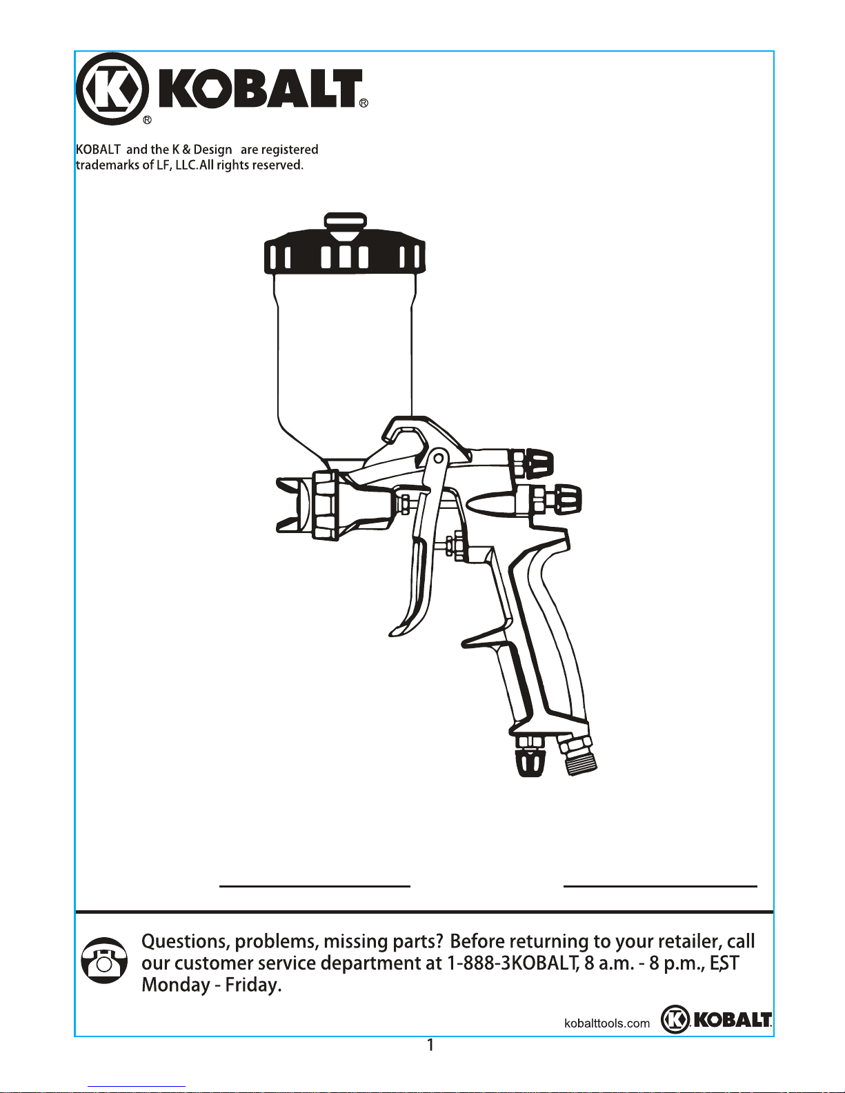
SMALL GRAVITY
FEED SPRAY GUN
ITEM #0301339
MODEL #SGY-AIR87TZ
ATTACH YOUR RECEIPT HERE
Serial Number Purchase Date
® ®
Page 2
2
TABLE OF CONTENTS
Safety Information ............................................................................................... 3
Assembly Instructions ..........................................................................................
Package Contents ................................................................................................ 5
Product Specifications .......................................................................................... 5
Preparation ..........................................................................................................
Operating Instructions ........................................................................................
Care and Maintenance .......................................................................................
Repair Instructions ..............................................................................................
Troubleshooting ...................................................................................................
Replacement Parts List ........................................................................................
Warranty ................................................................................................................
5
6
7
8
10
10
12
13
IMPORTANT: To operate correctly, this tool requires airflow that is at least 3.3 cubic feet per
minute (CFM) at 40 pounds per square inch (PSI). Check the specifications of your air compressor
to be sure that it can support both the minimum CFM and PSI required. An air hose may cause
up to 15 PSI drop in pressure, so you may need to set the output higher to maintain the required
pressure at the tool.
de maintenir un niveau adéquat.
IMPORTANTE: Para funcionar de manera correcta, esta herramienta requiere un flujo de aire de
por lo menos 3,3 pies cúbicos por minutos (CFM por sus siglas en inglés) para 40 libras por
pulgada cuadrada(PSI, por sus siglas en inglés). Revise las especificaciones de su compresora
de aire para asegurarse de que puede soportar tanto los CFM como las PSI mínimas requeridas.
Una manguera de aire comprimido puede causar una caída de hasta 15 PSI en la presión, de
manera que puede necesitar configurar la potencia más alta para mantener la presión requerida
en la herramienta.
IMPORTANT : Cet outil nécessite un débit d'air d'au moins 3,3 pi par minute à une pression de
3
3
aux exigencies minimales (pi /min et lb/psi ). L'utilisation d'un tuyau à air peut entraîner une chute
2
40 lb/psi . Vérifiez les spécifications de votre compresseur d'air afin de vous assurer qu'il satisfait
2
de pression de jusqu'à 15 lb/psi . Il peut donc s'avérer nécessaire d'augmenter la pression afin
2
3.3
CFM40PSI
Tool Requirements
Exigences relatives aux outils
Requisitos de herramientas
@
Page 3
3
SAFETY INFORMATION
Please read and understand this entire manual before attempting to assemble, operate
or install the product. If you have any questions regarding the product, please call
customer service at 1-888-3KOBALT, 8:00 a.m.-8:00 p.m., EST, Monday-Friday.
Do not allow children to operate tool, and keep children away from the work area.
Noise can harm your hearing. To safe guard your hearing always wear proper ear
protection.
Whenever doing maintenance on tool, proper impact resistant safety glasses and face
protection must be used.
During cleaning and flushing, be sure operator and others in the work areas are wearing
proper impact resistant eye and face protection. Solvents can be forcefully expelled
from fluid and air passages which may cause eye injury. Even small objects can in
jure
eyes and cause blindness.
Do not wear loose clothing, jewelry, or anything that may get caught or tangled when
using tool.
Before changing accessories, when making repairs, or when tool is not in use, always
first shut off air supply and release / drain air pressure from hose. Then disconnect too
l
from air supply or hose and store in a safe location.
Always have control of the air hose.
Never spray or direct air at yourself or anyone else.
Whipping hoses can cause serious injury. Always check for damaged or loose hoses
and fittings before use. Never use quick change couplings at tool. They add weight and
could fail due to vibration. Instead, add a hose whip connect coupling between air
supply and hose whip, or between hose whip and leader hose.
Always use the tool at a safe distance from other people in the work area.
Maintain tools with care, never use a tool that is leaking air, has missing or damaged
parts, or requires repairs.
Keep tools clean and properly oiled for best and safest performance. Follow lubrication
instructions for best and safest operation.
Follow assembly and repair instructions on how to properly change accessories.
Wiping or cleaning rags and other flammable waste materials that may have been
used on tool must be placed in a tightly closed metal container, and disposed of in a
proper manner.
Keep proper footing at all times. Do not overreach, as slipping, tripping, and or falling
can be a major cause of serious injury and or death. Be aware of excess hose in the
working area or work surface.
Check hoses for weak or worn connections before each use, and make certain that all
connections are secure.
Whenever possible, secure work with clamps, or vise so both hands can be free to
operate tool.
Repetitive motions, awkward positions and exposure to vibration can be harmful to
hands and arms.
Adequate exhaust must be provided to keep the air free of toxic materials. Use proper
work clothin t g o avoid direct skin contact.
Do not abuse hoses or connectors. Never carry the tool by the house or yank it to
disconnect it from a power supply. Keep hoses away from heat, oil, sharp edges, and
other sharp objects.
Page 4
4
SAFETY INFORMATION
Do not remove Brass baffle attached to front of gun body as special technical training
and tools are required. Only authorized service centers should remove this part.
To avoid cross-threading, all spray gun parts should be initially screwed in by hand
and hand tightened only. If the parts cannot be easily turned by hand, be sure you have
the correct parts, unscrew, realign, and secure properly in matching parts.
WARNING
CAUTION
SOME DUST CREATED BY PAINT SPRAYING, POWER SANDING, SAWING,
GRINDING, DRILLING, AND OTHER RELATED ACTIVITIES KNOWN TO THE
STATE OF CALIFORNIA TO CAUSE CANCER, BIRTH DEFECTS, AND OTHER
REPRODUCTIVE HARM. A LISTING OF CHEMICALS CAN BE OBTAINED FROM
www.oehha.ca.gov UNDER PROPOSITION 65. SOME EXAMPLES OF THESE
CHEMICALS ARE:
YOUR RISK FROM THESE EXPOSURES VARIES, DEPENDING ON HOW OFTEN
YOU DO THIS TYPE OF WORK. TO REDUCE YOUR EXPOSURE TO THESE
CHEMICALS WORK IN A WELL VENTILATED AREA, AND WORK WITH
WHICH ARE SPECIALLY DESIGNED TO FILTER MICROSOPIC PARTICLES.
LEAD FROM LEAD BASED PAINTS
PRODUCTS
CRYSTALLINE SILICA FROM BRICKS, CEMENT AND OTHER MASONRY
ARSENIC AND CHROMIUM FROM CHEMICALLY TREATED LUMBER
APPROVED SAFETY EQUIPMENT, SUCH AS A RESPRIATOR OR DUST MASKS
Use proper respirator whenever possible, or if there is a chance of inhaling sprayed
materials. The mask must be compatiblewith the materials being sprayed. Contact the
materials supplier for further details.
Solvent and coating can be highly combustibleespecially when sprayed.
Adequate exhaust must beprovided to keep air freeof flammable vapors.
Do not smoke in or near work area.
Always keep a fire extinguisher present in thework area.
Never spray near sources of ignition such sources such as pilot lights, welders, etc.
Halogenated hydrocarbonsolvents, andmethylene chloride, are not chemically
compatible with the aluminum that might beused in may spray system components.
The chemical reaction caused by thesesolventsreacting with aluminum can become
da
ngerous and lead to equipment failure and or equipment explosion.
Guns with stainless steel fluid passages may be used with thesesolvents; however
aluminum is widelyused in other spray applications suchas material pumps, cups, and
regulators, valves etc. Check all other equipment items before use and make sure they
can alsobe safely used with these solvents. Read the label or materialsafety data
sheet for the materials you intend to spray.
Operators andmaintenance personnel must be physically able to handle the bulk
weight, and power of the tool.
This tool is not intended forusing in explosive atmospheres andis not insulated for
contact with electricalpower sources.
Page 5
5
PREPARATION
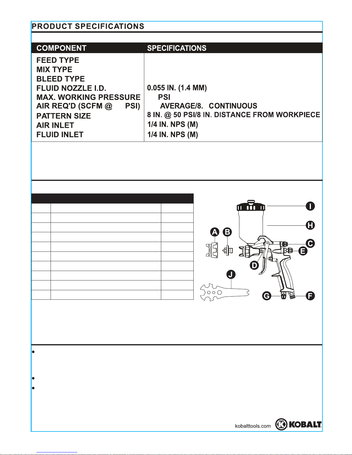
Before beginning assembly and operation of product, make sure all parts are present. Compare
parts with package contents list and diagram above. If any part is missing or damaged, do not
attempt to assemble or operate the product. Contact customer service for replacement parts.
Estimated Assembly Time: 3 minutes
Tools Required for Assembly: Wrench (included)
Quantity
1
1
1
1
1
1
1
1
1
1
Part
A
B
C
D
E
F
G
H
I
J
Description
PACKAGE CONTENTS
Air Cap w/Ring
Fluid Nozzle
Spray Pattern Adjustment Knob
Paint Needle
Fluid Adjustment Knob
Air Connection
Air Adjustment Knob
Plastic Cup
Cover
Wrench
3.3
6
40
40
GRAVITY
EXTERNAL
BLEEDER
Page 6
6
ASSEMBLY INSTRUCTIONS
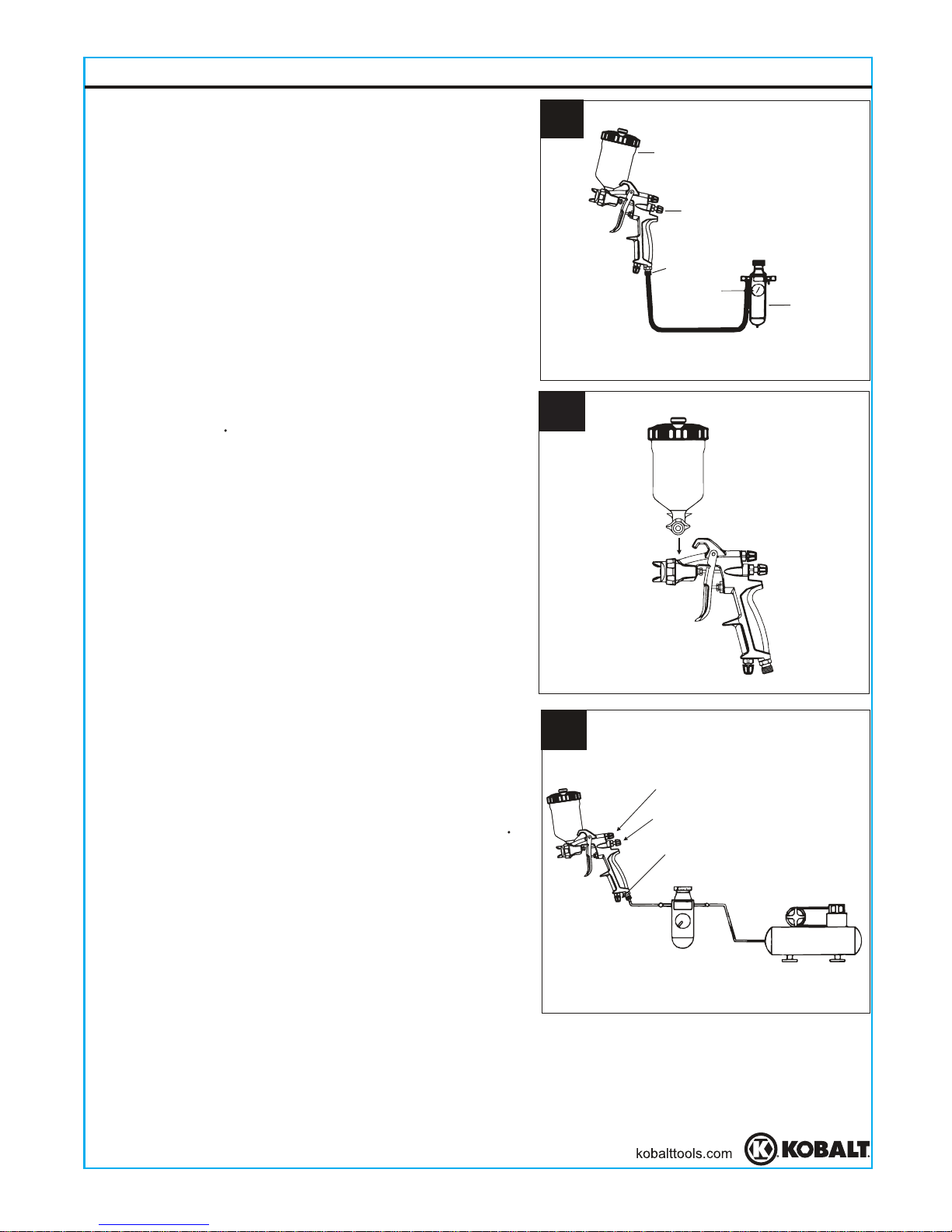
1
1. Take out spray gun and put on paint cup
(see Figure 2)
3
The life of this product and the efficiency of its
operation depend upon the knowledge of its
construction
,
usage and maintenance (See Figure 1.
Not all accessories shown are included).
2
Gravity Feed Cup
Fluid Adjustment Knob
Oil and
Water
Extractor
Atomization
Pressure Gauge
Air Hose
Air Inlet
Spray Pattern Adjustment Knob
Air Adjustment Knob
Fluid Adjustment Knob
2. Connect air tube to air intake connector from air
compressor; set pressure to 43 psi. Fully open air
adjustment knob and adjust the spray pattern
adjustment knob to proper range (See Fig 3. Oil and
water extractor and air compressor not included.)
Read and follow all directions before assembly or use
Page 7
7
ASSEMBLY INSTRUCTIONS
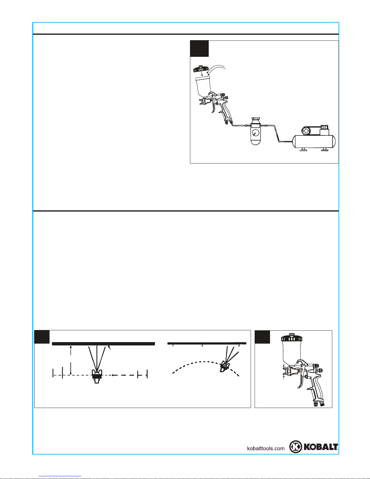
4
4. Pour paint into paint cup and put on cover
(See Fig 4. Oil and water extractor and air
compressor not included).
Load paint
OPERATION INSTRUCTIONS
Proper handling of the gun is essential for obtaining a good finish. The gun should be held at a
90 angle the surface being covered, and moved parallel to it. For precise control of the gun and
material, the trigger should be released before the end of the stroke. Hold the gun 6 to 12 inches
away from the surface depending on material and atomizing pressure. For a uniform finish, lap
each stroke over the preceding stroke, making sure the spray is smooth and wet. Using the
lowest possible atomizing air pressure will reduce over spray and provide maximum efficiency
(See Fig. 5).
O
6 to 12 inches
Start
stroke
Pull
trigger
Even and wet coat
Release
trigger
End of
stroke
RIGHT
Light coat Heavy coat
WRONG
5
During normal use, the air cap wings are horizontal and the air cap should be pointed up as
shown here (See Fig. 6). This provides a vertical fan-shaped pattern which gives maximum and
even material coverage as the gun is moved back and forth parallel to the surface being finished.
The air cap wings
are horizontal.
6
Page 8
8
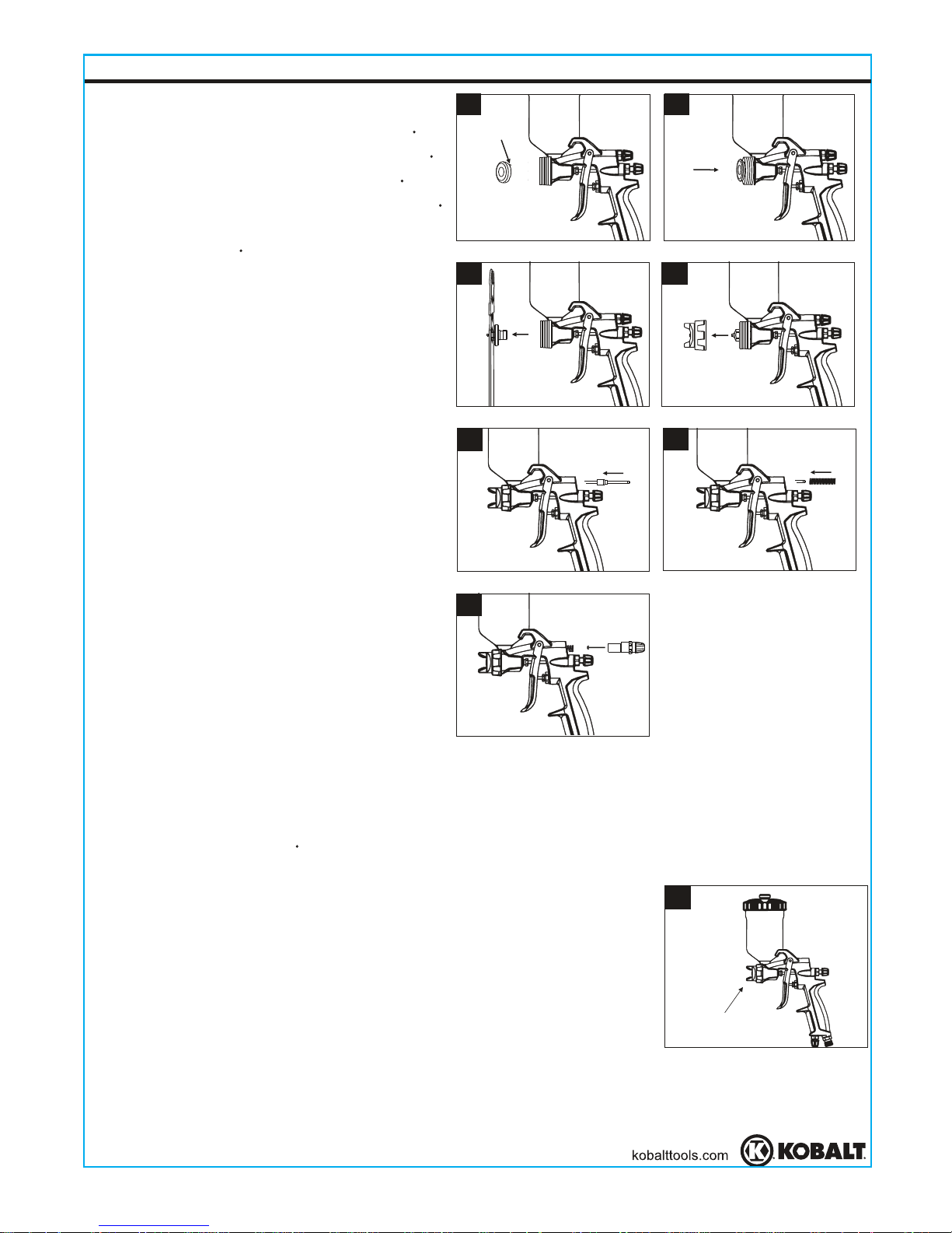
REPAIR INSTRUCTIONS
CAUTION:
Remove air pressure from air hose / gun.
Take care not to damage the seals on the gun body when
removing the air distribution ring.
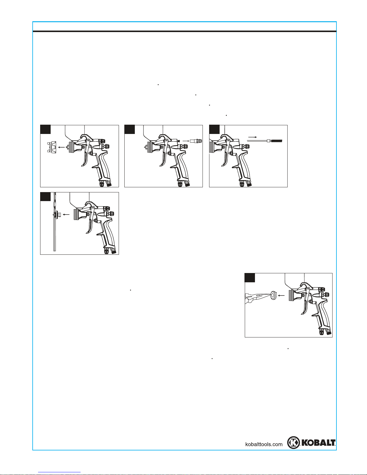
1. Remove the nozzle set:
a. Remove air cap w/ring (See Fig. 1)
b. Unscrew the fluid adjustment knob (See Fig. 2)
c. Pull out needle spring and paint needle (See Fig. 3)
d. Remove paint nozzle using wrench provided (See Fig. 4)
1 2 3
4
2. Pull out the air distribution ring using needle-nose pliers,
and remove dirt (See Fig. 5)
NOTE: Make sure that dirt has not settled in the sealing surfaces
and no scratches prevent optimum sealing performance.
5
pin marked with an arrow (1) fits smoothly into the hole marked (2) (See Fig. 6)
Then firmly push in the air distribution ring (See Fig. 7) Insert the paint nozzle and
tighten slightly. Then remove it again. Make sure the air distribution ring
fits securely against the gun body.
Reconnect air hose with spray gun and set to desired PSI.
Page 9
9
REPAIR INSTRUCTIONS
8
9
10
11
12
6
7
4. Mount the nozzle set:
a. Screw on paint nozzle (See Fig. 8)
b. Attach the air cap w/ring (See Fig. 9)
c. Put on paint needle (See Fig. 10)
d. Attach the needle spring (See Fig. 11)
e. Screw on the fluid adjustment knob
(See Fig. 12)
NOTE: Test spray pattern before use again.
During normal use, the air cap wings are horizontal and the air cap should be pointed up as
shown here (See Fig. 13)
This provides a vertical fan-shaped pattern which gives maximum
and even material coverage as the gun is moved back and forth parallel to the surface being
finished.
The air cap wings
are horizontal.
13
Page 10
10
CARE AND MAINTENANCE
To properly maintain and keep your small gravity feed sprayer working at its optimal performance,
it is recommended that the spray gun nozzle be cleaned and cleared of any clogs or debris buildup
using paint thinner, or lacquer thinner. DO NOT USE ANY ACID BASED SOLVENTS, AS ACID
BASED SOLVENTS CAN DAMAGE THE SPRAYER. Please consult with your local Lowes
retailer in choosing the right solvent materials.
15
14
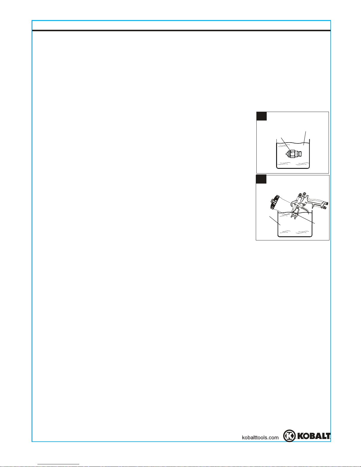
1. Pour enough solvent material(s) into container so that nozzle will be completely submerge in
solvent material
NOTE: There are two methods for properly submerging spray gun nozzle into cleaning solvent
material(s). The manufacturer recommends method 1:
Nozzle
Nozzle
Solvent material
Solvent
material
Method 2: Keeping the Spray gun nozzle attached to the spray gun
housing, submerge the front end of the spray gun only (See Fig. 15).
Make sure that only the spray gun nozzle is submerged in solvent
material(s). IF USING METHOD 2, AND NOT COMPLETELY
REMOVING SPRAY GUN NOZZLE, MAKE SURE A SUITALBLE
CONTAINER IS USED WHICH CAN NOT EASILY TIP OVER. IF
THE CONTAINER USED DOES TIP OVER, YOU WILL SPIL
SOLVENT MATERAIL(S), CAUSING A POTENTIAL SAFETY HAZZARD.
NOTE: Make sure that you never submerge any part of the spray gun
housing into solvent material(s), as air passages would become clogged
with dirty solvent. This would also cause the lubricant in the leather
packaging, and other gaskets inside the gun housing to dry out,
resulting in difficult operation and faster wear on the item which will cause poor spray performance.
2. Let nozzle sit in solvent material(s) for 3-5 minutes allowing solvent material(s) to break up any
build up of dirt and or debris on spray nozzle.
3. Remove nozzle from solvent material(s) and closely inspect the spray gun nozzle to ensure any
dirt or debris build up has been cleared.
NOTE: Depending on the paint and solvent material(s) used, steps 1-4 may need to be repeated
multiple times.
BEFORE PERFORMING ANY CLEANING OR MAINTENANCE REMOVE SPRAY GUN FROM
AIR SUPPLY AND KEEP AWAY FROM ANY INGITION SOURCES.
Method 1: Remove the spray gun nozzle completely from spray gun
and place into a container that will not cause solvent derogation when
solvent material(s) are added (See Fig. 14).
4. If debris or build up is still present use a non wire soft bristle brush and brush area of nozzle
that still contains dirt or debris, and repeat steps 1-4.
5. Once spray gun nozzle has been completely cleared of any dirt or debris, and is clean, wipe
nozzle clean with a clean cloth or rag.
6. Once nozzle has been properly cleaned reconnect nozzle to spray gun, and reconnect spray
gun to air supply, and test sprayer ensuing that sprayer is working properly. If you are at the
end of a project, when test spraying make sure you do not test spray having paint go through
the system as this will require you to begin the cleaning process again.
7. Once sprayer is working properly, make sure you follow the solvent manufactures
recommendations for properly discarding any dirty cloths, or rags that were used in the
cleaning process.
Storing
1. When not using spray gun, turn the fluid adjustment knob counterclockwise to open
which will reduce spring tension on needle fluid tip.
2. Spray gun must be well cleaned and lightly lubricated.
3. Store spray gun in a dry and safe place out of reach of children.
Page 11
TROUBLESHOOTING
11
a) Gun improperly adjusted.
b) Dirty air cap.
c) Fluid tip obstructed.
d) Sluggish needle.
Fan adjustment screw not seating
properly.
a) No air pressure at gun.
b) Fluid pressure too low with internal
mix cap and pressure tank.
c) Fluid control screw not open
enough.
d) Fluid too heavy for suction feed.
a) Packing nut loose.
b) Packing worn or dry.
a) Tighten, but not so tight as to grip
needle.
b) Replace packing or lubricate.
a) Check air supply and air lines.
b) Increase fluid pressure at tank.
c) Open fluid control screw.
d) Thin material or change to
pressure feed.
Clean or replace.
a) Re-adjust gun. Follow instructions
carefully.
b) Clean air cap.
c) Clean.
d) Lubricate.
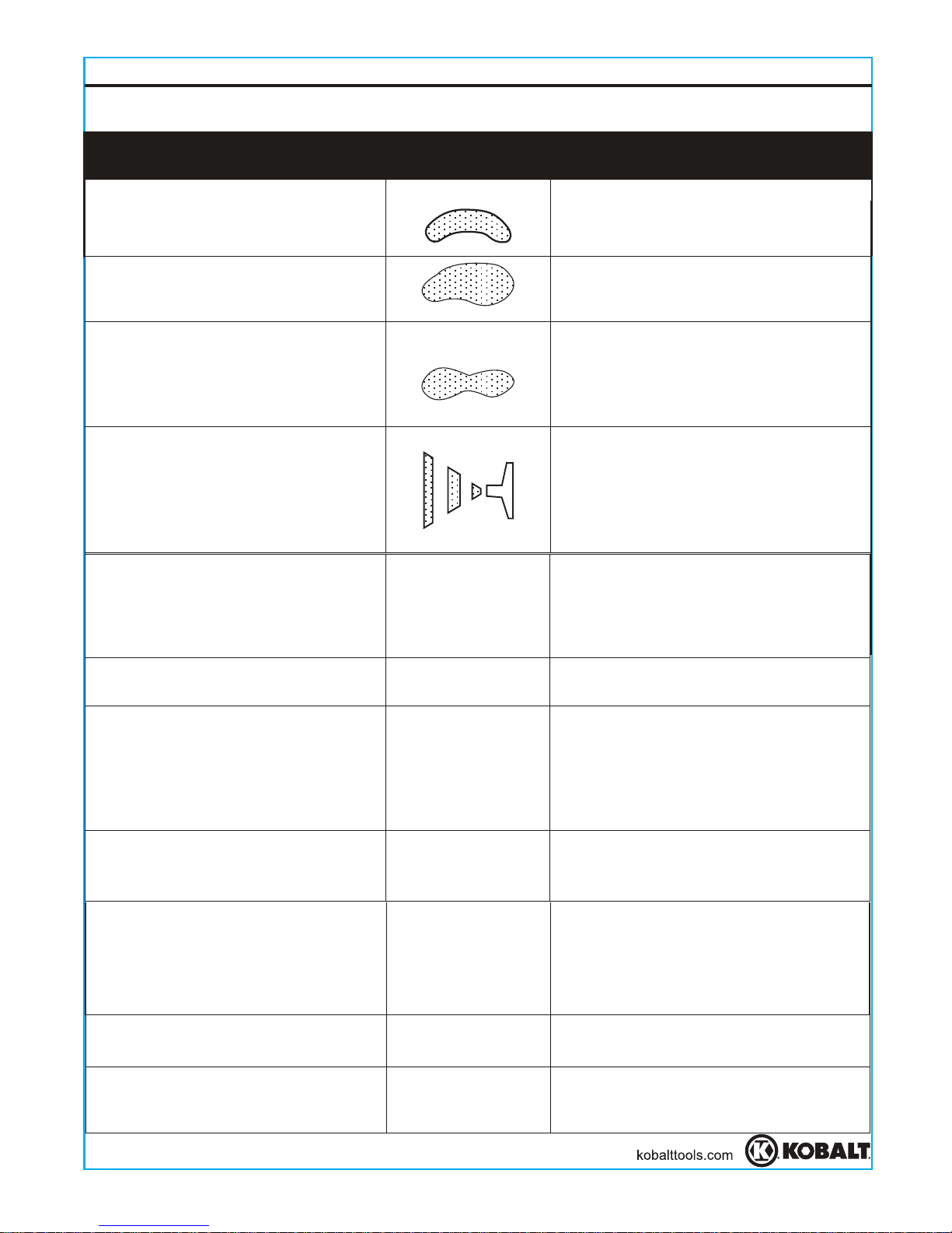
Unable to get
round spray.
Improper spray
pattern.
Will not spray.
Fluid leakage
from packing nut.
PROBLEM
SOLUTION
SPRAY PATTERN/
CONDITION
If you have any questions regarding the product, please call customer service at 1-888-3KOBALT,
8 a.m. - 8 p.m., EST, Monday - Friday.
Gun held too close to surface.
a) Dry packing.
b) Sluggish needle.
c) Tight packing nut.
d) Worn fluid nozzle or needle.
a) Gun held too far from surface.
b) Atomization pressure set too high.
Move gun further from surface.
a) Move gun closer to surface.
b) Adjust atomization pressure.
a) Lubricate.
b) Lubricate.
c) Adjust.
d) For pressure feed, replace with
new fluid nozzle and needle.
Dripping from
fluid tip.
Thick, dimpled
finish resembling
orange peel.
Thin, sandy
coarse finish.
a) Loose air nozzle.
b) Material around outside of air
nozzle has dried.
a) Atomization air pressure is set too
high.
b) Trying to spray a thin material in
too wide a pattern.
a) Packing around needle valve is dried
out.
b) Fluid nozzle loosely installed, or dirt
between nozzle and body.
c) Needle sealing damaged.
a) Back up knurled nut, put a few drops of
machine oil on packing, retighten nut.
b) Take off fluid nozzle, clean rear of nozzle
and seat in gun body. Replace nozzle
and bring in tight to body.
c) Replace seal.
a) Reduce air pressure.
b) Increase material control by turning fluid
adjustment knob to left, while reducing
spray width by turning spray pattern
adjustment knob to right.
a) Trigger air nozzle.
b) Take off air nozzle and wipe off fluid tip,
using a rag moistened with thinner.
Intermittent spray
Soak nozzle in solvent to loosen clog, then
blow air through until clean. To clean orifices
use a broom straw or toothpick. Never try to
detach dried material with sharp tool.
One side of nozzle is clogged.
Page 12

WARRANTY
12
This tool is warranted by the manufacturer to the original purchaser from the original
purchase date for three (3) years subject to the warranty coverage described herein.
This tool is warranted to the original user to be free from defect in material and
workmanship. If you believe that a tool is defective, return the tool, with proper proof
of purchase to the point of purchase. If it is determined that the tool is defective and
covered by this warranty, the distributor will replace the tool or refund the
purchase price.
This warranty is void if: defects in materials or workmanship or damages result from
repairs or alterations which have been made or attempted by others or the
unauthorized use of nonconforming parts; the damage is due to normal wear,
damage is due to abuse (including overloading of the tool beyond capacity), improper
maintenance, neglect or accident; or the damage is due to the use of the tool after
partial failure or use with improper accessories or unauthorized repair or alteration.
This warranty gives you specific legal rights, and you may also have other rights that
vary from state to state.
For warranty questions, call our customer service department at 1-888-3KOBALT,
8:00 a.m.-8:00 p.m. EST, Monday-Friday.
Page 13

REPLACEMENT PARTS LIST
13
Washer D=3
1 43 Non-drip control device 1
12
Spring
1 44
Washer D=3
1
13
Washer D=3
1 I Cover 1
14 O-ring2.5x2.1 1 46
Air Valve Spring
1
15 O-ring 8x1.5 1 47
Washer D=3
1
16 Pattern Adj. Knob 1 48 O-ring 2.5x2.1 1
17 Pattern Adj.Screw 1 49 O-ring 8x1.5 1
C
Spray pattern adj. knob
1 50
Pattern Adj. Knob
1
19 Screw M 5X2.5
5X2.5
1 51
Air Adj. Screw
1
20 Screw M 1 H
J
CPlastic up 1
E
Fluid adj. knob
1 G Air Adj. Knob 1
22
Fluid Adj. Screw Plug
1 54 Screw M2.5x5 1
23
Needle Housing Fluid
1 55 Fluid nipple 1
24 O-ring 10x1.8 1 56
Butterfly Nut
1
25 Snap Retainer d=4 1 57
Paint inlet Nozzle
1
26 Trigger 1 58 Cup holder 1
27 Gasket 1 59 Plug 1
28 O-ring 7x1.5 1 60
61
63
Plug 1
1
1
1
29 Needle spring 1
1
1
1
30 Washer
31 Washer
32 Trigger pin
Part No. Description Qty. Part No. Description Qty.
A Air cap w/Ring 1 D Paint Needle 1
2 Air nozzle washer 1 34 Spring 1
3 Air cap 1 35
Air Valve
1
4 Air cap washer 1 36 O-ring 6x1.5 1
B Fluid nozzle 1 37 O-ring 8x1.5 1
6 Gun body 1 38
Switch Seat
1
7
Washer
1 39 O-ring 2.5x1.5 1
8
Sealing gasket
1 40
Switch Screw Seat
1
9
Direction Screw
1 F Air connection 1
10
Pattern Needle
1 42
Air Inlet Valve
1
11
Printed in China
Gun holder
Wrench
Brush
Page 14

SMALL GRAVITY
FEED SPRAY GUN
14
Article #0301339
MODÈLE #SGY-NS87TZ
Numéro de série Date d'achat
KOBALT et le motif de K sont des marques
de commerce déposées de LF, LLC Tous droits
réservés.
JOIGNEZ VOTRE REÇU ICI
Des questions, des problèmes, des pièces manquantes? Avant de
retourner l'article au détaillant, communiquez avec notre service à la
clientèle au 1 888 3KOBAL , entre 8 h et 20 h (HNE), du lundi au vendredi.
® ®
Page 15

15
TABLE DES MATIÈRES
Consignes de sécurité
....................................................................................... 16
Caractéristiques du produit .................................................................................. 18
Contenu de l'emballage ....................................................................................... 18
Préparation .......................................................................................................... 18
Directives d’assemblage ..................................................................................... 19
Instructions d’utilisation ...................................................................................... 20
Entretien .............................................................................................................. 23
Dépannage ......................................................................................................... 24
Garantie ............................................................................................................. 25
Liste des pièces de rechange ............................................................................... 26
Instructions pour la réparation ........................................................................... 21
Page 16

16
CONSIGNES DE SÉCURITÉ
Veuillez vous assurer de lire et de comprendre l'intégralité du présent guide avant
u
d'assembler, d' tiliser ou d'installer ce produit. Si vous avez des questions concernant
ce produit, veuillez téléphoner au service à la clientèle au 1 888 3KOBALT, entre 8 h et
20 h (HNE), du lundi au vendredi.
Ne laissez pas les enfants utiliser l’outil et gardez les enfants à distance de l’aire de travail.
Le bruit peut détériorer votre ouïe. Afin de protéger votre ouïe, portez toujours des
protecteurs auditifs appropriés.
Lorsque vous entretenez l’outil, portez un protecteur facial et des lunettes de sécurité
résistant aux chocs.
Lors du nettoyage et du rinçage, assurez-vous que l’utilisateur et les autres personnes
présentes dans l’air de travail portent un protecteur facial et des lunettes de sécurité
résistant aux chocs appropriés. Les solvant
s peuvent être expulsés sous la pression de
l’air et des fluides et causer des blessures aux
yeux. Les petits objets peuvent ég
alement
blesser les yeux et entraîner la cécité.
Ne portez pas de vêtements amples, de bijoux ni tout autre article qui pourrait
s’accrocher ou s’emmêler dans l’outil lors de son utilisation.
Coupez l’alimentation en air et évacuez la pression d’air du tuyau avant de changer les
accessoires ou d’effectuer des réparations, ainsi que lorsque vous n’utilisez pas l’outil.
Débranchez ensuite l’outil de l’alimentation en air et rangez-le dans un endroit sécuritaire.
Gardez toujours la maîtrise du tuyau à air.
Ne pointez jamais le jet d’air vers vous-même ou une autre personne.
Le cinglage des tuyaux souples peut entraîner de graves blessures.Vérifiez toujours les
tuyaux et les raccords pour déceler des dommages ou desserrages éventuels. N'utilisez
jamais de raccords à changement rapide sur l'outil. Ils ajoutent du poids et pourraient
Gardez toujours l’outil à une distance sécuritaire des personnes présentes dans l’aire
de travail.
Entretenez soigneusement les outils. N’utilise
z jamais un outil qui présente une fuite d’air,
auquel il manque des pièces, dont des pièces son
t endommagées ou qui nécessite des réparations
.
Gardez les outils propres et adéquatement huilés pour un rendement optimal et sécuritaire.
Suivez les instructions pour la lubrification afin d’assurer un fonctionnement optimal et sécuritaire.
Suivez les instructions pour l’assemblage et les réparations pour changer les
accessoires correctement.
Demeurez stable sur vos pieds et gardez l'équilibre en tout temps. Glisser, trébucher ou
Vérifiez les tuyaux souples pour déceler tout signe de faiblesse ou d'usure avant de les
utiliser et assurez-vous que toutes les connexions sont sûres.
Prenez soin des tuyaux souples et des connecteurs. Ne transportez jamais l'outil par le
tuyau souple et ne le tirez pas d'un coup sec pour le débrancher de l'alimentation électrique.
tenez les tuyaux éloignés des sources de chaleur, de l’huile, des rebords coupants
et d’autres objets tranchants.
se desserrer en raison des vibrations. Ajoutez plutôt une amorce de tuyau et fixez le
raccord entre l'arrivée d'air et l'amorce ou entre l'amorce et le tuyau principal.
chuter peut causer des blessures graves ou le décès. Faites attention au surplus de
tuyau laissé sur le passage ou la surface de travail.
Si possible, fixez la pièce sur laquelle vous travaillez avec des pinces ou un étau afin de
pouvoir vous servir de vos mains pour faire fonctionner l'outil.
Les mouvements répétitifs effectués pendant le travail, les positions inconfortables et
l'exposition aux vibrations peuvent se révéler douloureux pour les mains et les bras.
Une sortie de ventilation doit être prévue pour maintenir l'air exempt de matériaux toxiques.
Gardez une posture sécuritaire en tout temps. Ne vous étirez pas pour étendre votre
portée; vous risqueriez de glisser, de trébucher ou de tomber et de subir des blessures
graves ou mortelles. Faites attention à l’excédent du tuyau à air et aux prises
d’alimentation de l’aire de travail.
Portez des vêtements de travail appropriés pour éviter le contact direct avec la peau.
Page 17

17
ING
Portez un masque respiratoire approprié lorsque possible, ainsi que lorsqu’il y a un risque
d’inhalation des matériaux vaporisés. Le masque doit être compatible avec les matériaux
vaporisés. Communiquez avec le fournisseur des matériaux pour plus de détails.
Les solvants et les apprêts peuvent se révéler très combustibles, tout particulièrement
lorsqu'ils sont pulvérisés.
Une sortie de ventilation doit être prévue pour maintenir l'air exempt de vapeurs inflammables.
Ne fumez pas sur le lieu de travail ou à proximité.
Ayez toujours un extincteur sur le lieu de travail.
Ne pulvérisez jamais près des sources d'inflammation telles que les flammes de veilleuses,
les machines à souder, etc.
Les halons, par exemple les dichlorométhanes, ne sont pas chimiquement compatibles avec
l'aluminium qui pourrait être utilisé dans de nombreux composants du système. La réaction
chimique causée par ces solvants réagissant à l'aluminium peut se révéler dangereuse et
provoquer une explosion de l'équipement.
Les pistolets munis de conduites de fluide en acier inoxydable peuvent être utilisés avec ces
solvants. Toutefois, l'aluminium est largement utilisé dans d'autres outils de pulvérisation tels
q
ue les pompes à pulvériser, les godets et les régulateurs, les soupapes, etc. Vérifiez toutes
les pièces de l'équipement avant de vous en servir et assurez-vous qu'elles peuvent être
utilisées en toute sécurité avec ces solvants. Lisez l'étiquette et la fiche signalétique de sécurité
du matériau que vous avez l'intention de pulvériser.
Les opérateurs et le personnel d'entretien doivent avoir les capacités physiques
nécessaires pour manier un outil de ce volume, de ce poids et de cette puissance.
Cet outil n'est pas conçu pour être utilisé dans des atmosphères explosives et n'est pas isolé
de façon à pouvoir supporter un contact avec les sources d'alimentation électrique.
CONSIGNES DE SÉCURITÉ
AVERTISSEMENT
LA POUSSIÈRE CRÉÉE PENDANT LE PONÇAGE, LE SCIAGE, LE POLISSAGE, LE
PERÇAGE ET D'AUTRES ACTIVITÉS PEUT CONTENIR DES PRODUITS CHIMIQUES
RECONNUS PAR L'ÉTAT DE LA CALIFORNIE COMME ÉTANT LA CAUSE DE CANCERS,
D'ANOMALIES CONGÉNITALES ET D'AUTRES PROBLÈMES LIÉS AUX FONCTIONS
AU www.oehha.ca.gov, CONFORMÉMENT À LA PROPOSITION 65. VOICI
QUELQUES-UNS DE CES PRODUITS CHIMIQUES :
DU PLOMB PROVENANT DE PEINTURES À BASE DE PLOMB;
DE LA SILICE CRISTALLINE PROVENANT DE LA BRIQUE, DU CIMENT OU
D
'AUTRES MATÉRIAUX DE MAÇONNERIE;
DE L'ARSENIC ET DU CHROME PROVENANT DU BOIS D'ŒUVRE TRAITÉ AVEC
UN PRODUIT CHIMIQUE.
REPRODUCTRICES. VOUS POUVEZ OBTENIR LA LISTE DES PRODUITS CHIMIQUES
LES RISQUES LIÉS À L’EXPOSITION À CES PRODUITS VARIENT SELON LE NOMBRE
DE FOIS OÙ VOUS PRATIQUEZ CES ACTIVITÉS. AFIN DE LIMITER VOTRE
EXPOSITION À CES PRODUITS CHIMIQUES, TRAVAILLEZ DANS UN ENDROIT BIEN
VENTILÉ ET UTILISEZ DE L’ÉQUIPEMENT DE SÉCURITÉ APPROUVÉ, TEL QU’UN
APPAREIL RESPIRATOIRE OU UN MASQUE ANTIPOUSSIÈRE CONÇUS
SPÉCIALEMENT POUR FILTRER LES PARTICULES MICROSCOPIQUES.
Page 18

18
CARACTÉRISTIQUES DU PRODUIT
CARACTÉRISTIQUES
COMPOSANTE
ENTRÉE D’AIR
.
NE RETIREZ PAS le déflecteur en laiton fixé à l'avant du corps du pistolet car une
formation technique spéciale et certains outils
sont nécessaires. Le retrait de cette
pièce devrait être confié aux centres de réparation et d'entretien autorisés.
CONSIGNES DE SÉCURITÉ
1
1
1
1
1
1
1
1
1
1
A
B
C
D
E
F
G
H
I
J
Quantité
Pièce Description
Obturateur d’air avec anneau
Buse à fluide
Pointeau à peinture
Bouton de réglage du fluide
Raccord d'air
Bouton de réglage de l’air
Recipiente de plástico
Cubierta
Clé
Bouton de réglage du jet
CONTENU DE L'EMBALLAGE
PRÉPARATION
Avant de commencer l'assemblage et d'utiliser le produit, assurez-vous de disposer de toutes les
pièces. Comparez les pièces dans l'emballage avec la liste et le tableau ci-dessus. Si des pièces
sont manquantes ou endommagées, ne tentez pas d'assembler ou d'utiliser le produit.
Communiquez avec le service à la clientèle pour obtenir des pièces de rechange.
Temps d'assemblage approximatif : 3 minutes
Accessoires requis pour l'assemblage : Clé (comprise)
Pour éviter de déformer le filetage, toutes les pièces du pistolet de pulvérisation
devraient d’abord être serrées solidement à la main. Si le serrage à la main s’avère
difficile, assurez-vous qu’il s’agit des bonnes pièces. Dévissez-les, ajustez-les et
tentez de les visser de nouveau avec plus de force.
TYPE D’ALIMENTATION
TYPE DE MÉLANGE
TYPE DE PURGE
DIAMÈTRE INTÉRIEUR DE
LARGEUR DU JET
ENTRÉE DE FLUIDE
LB/PO )
2
AIR REQUIS (PI /MIN À 40
3
PRESSION DE SERVICE MAXIMALE
GRAVITÉ
EXTERNE
PURGEUR
1,4 MM (0,055 PO)
40 LB/PO
2
3,3 EN MOYENNE/8,6 EN CONTINU
20,32 CM (8 PO) À 50 LB/PO /À 20,32 CM (8 PO)
DE LA PIÈCE
2
1/4 PO NPS (M)
1/4 PO NPS (M)
MISE EN GARDE
Page 19

19
1
3
2
Godet de pistolet
à gravitation
Molette de réglage du fluide
Extracteur
d'huile
et d'eau
Manomètre
de pulvérisation
Tuyau d'air souple
Arrivée d'air
DIRECTIVES D'ASSEMBLAGE
3. Raccordez le tube d’air au connecteur d’entrée
d’air du compresseur d’air et réglez la pression
à 60 lb/po2. Tournez complètement le bouton
de réglage du débit d’air en position ouverte et
tournez le bouton de réglage du jet en position
adéquate. (Consultez la figure. 3. L’extracteur
d’huile et d’eau et le compresseur d’air ne
sont pas inclus.)
Molette de réglage de la répartition
de la pulvérisation
Molette de régulation de l'air
Molette de réglage du fluide
Ce pistolet de pulvérisation est d'une fabrication
robuste; il a été conçu pour offrir une valeur
exceptionnelle. La durée de vie et l'efficacité de ce
produit dépendent des connaissances qu'ont les
utilisateurs relativement à sa fabrication, à son
utilisation et à son entretien. (Consultez la figure 1..
Certains accessoires illustrés ne sont pas inclus.)
2.
Prenez le pistolet de pulvérisation et placez-le sur
le réservoir à peinture. (Consultez la figure 2.)
Page 20

20
4
La manipulation appropriée du pistolet est essentielle à l’obtention d’un fini adéquat. Le pistolet
doit être tenu à un angle de 90° de la surface couverte et il doit être déplacé parallèlement à
celle-ci. Pour plus de précision, gardez le pistolet à une distance de 15,24 cm à 30,48 cm de la
surface et des matériaux. Relâchez la gâchette avant la fin du trait pour obtenir une couverture
uniforme. Pour obtenir une couverture uniforme, tenez le pistolet à une distance de 15,24 cm à
30,48 cm, selon le matériau pulvérisé, la pression de pulvérisation et la surface couverte. Pour
un fini uniforme, faites chevaucher chaque trait sur le trait précédent, en vous assurant que la
couverture est lisse et humide. En utilisant le réglage de pression de vaporisation le plus faible,
vous réduirez les risques de surpulvérisation et vous jouirez d’une efficacité maximale.
(Consultez la fig. 5.)
5
Lors de l’utilisation normale, les ailettes de l’obturateur d’air sont à l’horizontale et l’obturateur
d’air est orienté vers le haut, tel qu’il est illustré. (Consultez la fig. 6) Ainsi, vous obtiendrez un
jet vertical en forme d’éventail et vous vous assurerez d’obtenir une couverture optimale et
uniforme (déplacez le pistolet dans un mouvement de va-et-vient parallèle à la surface).
6
4. Versez la peinture dans le réservoir à peinture
et mettez le couvercle en place. (Consultez la
fig. 4. L’extracteur d’huile et d’eau et le
compresseur d’air ne sont pas inclus.)
Chargez la peinture
DIRECTIVES D'ASSEMBLAGE
INSTRUCTIONS D'UTILISATION
Commencez
le passage
Tirezla
gâchette
Couche uniforme
et mouillée
Relâchez
la gâchette
Findu
passage
Couche
légère
Couche
épaisse
INADÉQUAT
15,25 à 30,50 cm
(6 à 12 po)
Les ailettes du
capuchon d'air
sont à l'horizontale.
DROITE
Page 21

21
MISE EN GARDE: Veillez à ne pas endommager les joints du corps du
pistolet lorsque vous retirez la bague de distribution d'air.
1. Retirez l'ensemble de la buse :
a. Retirez le bouchon d'air avec bague (Voir fig. 1)
b. Dévissez la molette de réglage du fluide. (Voir fig. 2)
c. Retirez le ressort de l'aiguille et l'aiguille à peinture. (Voir fig. 3)
d. Retirez la buse à peinture à l'aide de la clé fournie. (Voir fig. 4)
2. Retirez la bague de distribution d'air à l'aide de pinces à becs
pointus et enlevez la saleté. (Voir fig. 5)
REMARQUE: Assurez-vous que la saleté ne s'est pas accumulée
sur les surfaces des joints et que des rayures n'altèrent pas la
performance de l'étanchéité.
marquée d'une flèche (1) s'engage sans entrave dans l'orifice marqué (2). (Voir fig. 6.) Ensuite,
enfoncez fermement la bague de distribution d'air. (Voir fig. 7.) Insérez la buse à peinture et
serrez légèrement. Retirez-la de nouveau. Assurez-vous que la bague de distribution d'air est
bien ajustée contre le corps de la bague.
Éliminez la pression d’air des tuyaux à air du pistolet de pulvérisation.
Raccordez le tuyau à air au pistolet de pulvérisation et réglez à la
pression en lb/po souhaitée.
INSTRUCTIONS POUR LA RÉPARATION
2
1 2 3
4
5
Page 22

22
13
4. Montez l'ensemble de la buse :
a. Vissez la buse à peinture. (Voir fig. 8)
a. Fixez le bouchon d'air avec bague.
(Voir fig. 9)
c. Mettez l'aiguille à peinture en place.
(Voir fig. 10)
d. Fixez le ressort d'aiguille. (Voir fig. 11)
e. Vissez la molette de réglage du fluide.
(Voir fig. 12)
REMARQUE: Effectuez un essai de pulvérisation pour vérifier la répartition avant d'utiliser de
nouveau l'outil.
Pendant l'utilisation normale, les ailettes du bouchon d'air sont à l'horizontale et le bouchon d'air
devrait pointer tel qu'il est illustr. (Voir fig. 13.) Vous obtenez ainsi la répartition verticale en forme
d'éventail qui procure une couverture maximale et uniforme tandis que le pistolet fait des
aller-retour parallèlement à la surface qui est revêtue.
Les ailettes du
capuchon d'air
sont à l'horizontale.
INSTRUCTIONS POUR LA RÉPARATION
8
9
10
11
12
6
7
Page 23

23
15
14
La buse
La buse
Solvant
Solvant
ENTRETIEN
Pour bien entretenir et garder votre pulvérisateur de travail à sa performance optimale, nettoyez
la buse de pulvérisation et enlevez-en les obstructions et les débris à l’aide d’un diluant à peinture
ou d’un diluant à peinture-laque seulement. N’UTILISEZ PAS DE SOLVANT À BASE D’ACIDE,
CAR CES PRODUITS PEUVENT ENDOMMAGER LE PISTOLET DE PULVÉRISATION.
N’hésitez pas à consulter votre détaillant Lowes afin de choisir le bon solvant.
1. Versez suffisamment de solvant dans un récipient pour que la buse soit complètement immergée.
REMARQUE : Il existe deux moyens d’immerger correctement la buse du pistolet de pulvérisation
dans le solvant. Le fabricant recommande l’utilisation de la méthode 1.
Méthode 2 : laissez la buse du pistolet de pulvérisation fixée au
boîtier du pistolet et immergez complètement la partie avant de
celui-ci (consultez la figure 15). Assurez-vous que seule la buse du
pistolet de pulvérisation se trouve immergée dans le solvant. SI VOUS
CHOISISSEZ LA MÉTHODE 2 ET NE RETIREZ PAS
COMPLÈTEMENT LA BUSE, ASSUREZ-VOUS D’UTILISER UN
CONTENANT ADÉQUAT QUI NE SE RENVERSE PAS
FACILEMENT. SI LE CONTENANT SE RENVERSAIT, LE SOLVANT
RÉPANDU ENTRAÎNERAIT UN RISQUE POUR LA SÉCURITÉ.
REMARQUE : Assurez-vous de ne jamais immerger aucune partie du
boîtier du pistolet de pulvérisation dans le solvant, car le solvant souillé
pourrait boucher les conduits d’air. Cela pourrait également assécher le
lubrifiant de la garniture en cuir et des autres joints se trouvant à
l’intérieur du pistolet, ce qui rendrait l’utilisation difficile, accélérerait l’usure de l’article et
entraînerait un mauvais rendement.
2. Laissez la buse reposer durant 3 à 5 minutes, afin de permettre au solvant de dissoudre les
débris et les accumulations.
3. Remove nozzle from solvent material(s) and closely inspect the spray gun nozzle to ensure any
dirt or debris build up has been cleared.
REMARQUE : Selon la peinture et le solvant utilisés, vous devrez peut-être répéter les étapes 1
à 4 plusieurs fois.
VANT DE PROCÉDER AU NETTOYAGE OU À L’ENTRETIEN, DÉBRANCHEZ LE PISTOLET
DE PULVÉRISATION DE L’ALIMENTATION EN AIR ET TENEZ-LE LOIN DES SOURCES
D’INFLAMMATION.
Méthode 1: retirez la buse du pistolet de pulvérisation et déposez-la
dans un récipient qui n’altérera pas le solvant (consultez la figure 14).
4. S’ils ne sont pas complètement dissous, brossez l’endroit où se trouvent les saletés à l’aide
d’une brosse à soies souples et répétez les étapes 1 à 4.
5. Une fois la buse complètement nettoyée, essuyez-la avec un linge propre.
6. Une fois le nettoyage terminé, raccordez la buse au pistolet de pulvérisation ainsi que
l’alimentation en air, puis testez le pistolet afin de vérifier s’il fonctionne correctement. Si vous
avez terminé votre projet, assurez-vous qu’il n’y a pas de peinture dans le système lorsque
vous le testez. Si tel est le cas, vous devrez recommencer le processus de nettoyage.
7. Lorsque le pistolet de pulvérisation fonctionne correctement, suivez les consignes du fabricant
de solvant afin de vous débarrasser adéquatement des linges utilisés pendant le nettoyage.
Entreposage
1. Lorsque vous n'utilisez pas le pistolet de pulvérisation, tournez le bouton de réglage
du fluide dans le sens contraire des aiguilles d'une montre afin de réduire la tension
du ressort sur le bout du pointeau du fluide.
2. Il faut bien nettoyer et légèrement lubrifier le pistolet de pulvérisation.
3. Rangez le pistolet de pulvérisation dans un endroit sec et sûr, hors de la portée des
enfants.
Page 24

24
DÉPANNAGE
Pour obtenir des pièces de rechange, communiquez avec notre service à la clientèle
au 1 888 3KOBALT, entre 8 h et 20 h (HNE), du lundi au vendredi.
PROBLÈME SOLUTION
RÉPARTITION/ÉTAT
DE LA PULVÉRISATION
Faites tremper la buse dans du solvant pour
la déboucher, puis nettoyez à l'air comprimé.
Pour nettoyer les orifices, utilisez une paille
de balai ou un cure-dent. N'essayez pas de
détacher du matériau sec à l'aide d'un outil
coupant.
Un côté de la buse est obstrué.
a) La pression d'air de pulvérisation est
réglée à un niveau trop élevé.
b) Vous essayez de pulvériser un
matériau fin selon une répartition
trop large.
a) Réduisez la pression de l'air.
b) Contrôlez davantage le matériau en
tournant la molette de réglage du fluide
vers la gauche tout en réduisant la
largeur de la pulvérisation en tournant la
molette de réglage de la répartition de la
pulvérisation vers la droite.
A) La buse à air est mal ajustée.
b) Le matériau a séché sur le pourtour
extérieur de la buse à air.
a) Faites basculer la buse à air.
b) Retirez la buse à air et essuyez la pointe
de la buse avec un chiffon humecté de
diluant.
a) La garniture du pourtour de la soupape
de l'aiguille a séché.
b) La buse à fluide n'a pas été assez
serrée à l'installation ou il y a de la
saleté entre la buse et le corps de l'outil.
c) Le joint de l'aiguille est endommagé.
a) Desserrez l'écrou moleté, versez
quelques gouttes d'huile
sur la garniture et resserrez l'écrou.
b) Enlevez la buse à fluide, nettoyez
l'arrière de la buse et posez le corps du
pistolet. Remettez la buse en place et
ajustez-la contre le corps du pistolet.
c) Replacez le joint.
pour machines
Pulvérisation
intermittente
a) Le pistolet n'est pas réglé
correctement.
b) Le bouchon d'air est sale.
c) La pointe de la buse à fluide est
obstruée.
d) L'aiguille est lente.
La vis de réglage du jet en éventail
n'est pas correctement assise.
a) Il n'y a pas de pression d'air au pistolet.
b) La pression du fluide est trop basse
lorsque le bouchon du mélange interne
est en place et le godet est sous pression.
c) La vis de commande du fluide n'est pas
suffisamment ouverte.
d) Le fluide est trop lourd pour l'aspiration.
a) L'écrou de la garniture est desserré.
b) La garniture est usée ou sèche.
a) La garniture est sèche.
b) L'aiguille est lente.
c) L'écrou de la garniture est trop
serré.
d) La buse ou l'aiguille à fluide est
usée.
a) Lubrifiez.
b) Lubrifiez.
c) Réglez.
d) Pour l'alimentation sous pression,
remplacez la buse et l'aiguille à fluide.
a) Serrez, mais pas excessivement pour
éviter que l'aiguille ne se grippe.
b) Remplacez la garniture ou lubrifiez.
a) Réglez de nouveau le pistolet. Suivez
attentivement les instructions.
b) Nettoyez le bouchon d'air.
c)
Nettoyez.
d) Lubrifiez.
Des gouttes fuient
de la buse à fluide.
Il est impossible
d'obtenir une
pulvérisation ronde.
La répartition de la
pulvérisation est
inadéquate.
Il est impossible de
pulvériser.
Du fluide fuit de
l'écrou de la garniture.
a) Vérifiez l'arrivée et les conduites d'air.
b) Augmentez la pression du fluide dans
le godet.
c) Ouvrez la vis de commande du fluide.
d) Amincissez le matériau ou optez pour
l'alimentation sous pression.
Nettoyez-la ou remplacez-la
Page 25

25
Le pistolet est tenu trop près de la
surface.
a) Le pistolet est tenu trop loin de la
surface.
b) La pression de la pulvérisation est
réglée à un niveau trop élevé.
Éloignez le pistolet de la surface.
a) Avancez le pistolet plus près de la surface.
b) Réglez la pression de la pulvérisation.
La finition est épaisse,
alvéolée et ressemble
à de la peau d'orange.
La finition est à gros
grains grossiers.
TROUBLESHOOTING
Pour obtenir des pièces de rechange, communiquez avec notre service à la clientèle
au 1 888 3KOBALT, entre 8 h et 20 h (HNE), du lundi au vendredi.
PROBLÈME SOLUTION
RÉPARTITION/ÉTAT
DE LA PULVÉRISATION
Cet outil est garanti par le fabricant pour une période de trois (3) ans à partir de la
date d'achat, selon les modalités décrites aux présentes.
Cet outil est garanti contre les défauts de matériaux et de fabrication. Si vous croyez
qu'il est défectueux, retournez-le, accompagné d'une preuve d'achat acceptable, au
point de vente d'origine. Si l'outil est jugé défectueux et qu'il est couvert par la
présente garantie, le distributeur l'échangera ou vous remboursera le prix d'achat.
Cette garantie sera annulée si : les défauts de matériaux ou de fabrication ou les
dommages résultent de réparations ou de modifications non autorisées, de
l'utilisation de pièces non conformes, de l'usure normale, d'un usage abusif
(notamment une surcharge de l'outil), d'un entretien inadéquat, d'une négligence,
d'un accident, d'une utilisation après une défaillance partielle ou de l'utilisation
d'accessoires inappropriés.
Cette garantie vous confère des droits précis. Il est possible que vous disposiez
également d'autres droits, qui varient d'un État ou d'une province à l'autre.
Pour toute question concernant la garantie, communiquez avec le service à la
clientèle au 1 888 3KOBALT, entre 8 h et 20 h (HNE), du lundi au vendredi.
GARANTIE LIMITÉE DE TROIS ANS
Page 26

26
D=3
1 43 Dispositif anti-goutte 1
12 1 44
Arandela D=3
Arandela D=3
1
13
D=3
1
1
1
I Cubierta 1
14 46
Ressort de la soupape d’air
Junta tórica de 2.5x2.1
1
15 47
1
1
16
48
17
49 Junta tórica de 8x1.5 1
C 1
1
1
1
1
50 1
19 Vis M 5X2.5
5X2.5
51
Vis de réglage de l'air
Perilla de ajuste de modalidad
1
20 H
J
Recipiente de plástico 1
1
1
E
Bouton de réglage du fluide
1 G
22
Bouchon à vis du fluide
1 54
23
Pointeau du fluide
1
1
1
55
Boquilla acopladora de fluido
1
24 56
Écrou à ailettes
1
25 57
Embout d’entrée de la peinture
1
26 Gâchette 1 58 Support du gobelet 1
27 Joint 1
1
1
1
1
1
59 Fiche
Fiche
1
28 60
61
63
1
1
1
1
29
30
31
32
Pieza No.
A D Pointeau à peinture
Descripción Cant.Pieza No. Descripción Cant.
1
2 34 Resorte 1
3 1
1
1
1
1
1
35
Soupape d'air
1
4 36 Junta tórica de 6x1.5 1
B 37 Junta tórica de 8x1.5 1
6 38
39
Siège de l’interrupteur
Junta tórica de2.5x1.5
1
17 1
8 1 40
Vis du siège de l’interrupteur
1
9 1 F Raccord d’air 1
10
Motif de l'aiguille
1 42
Robinet d’entrée d’air
1
11
Obturateur d’air avec anneau
Rondelle de buse à air
Obturateur d’air
Rondelle d’obturateur d’air
Buse à fluide
Corps du pistolet
Rondelle
Joint d’étanchéité
Vis d’orientation
Rondelle
Rondelle
Ressort
Joint torique de 2,5 x2,1
Joint torique de 8 x1,5
Joint torique de 10 x1,8
Joint torique de 7 x1,5
Bouton de réglage du jet
Vis de réglage du jet
Bouton de réglage du jet
Vis M
Dispositif de retenue à pression p=4
Ressort de pointeau
Rondelle
Rondelle
Goupille de gâchette
Imprimé en Chine
Bouton de réglage de
l’air
Vis M2.5x5
LISTE DES PIÈCES DE RECHANGE
Support à pistolet
Clé
Douille
Page 27

27
ARTÍCULO #0301339
MODELO #SGY-AIR87TZ
PISTOLA ATOMIZADORA
GRANDE ALIMENTADA
POR GRAVEDAD
ADJUNTE SU RECIBO AQUÍ
Número de serie Fecha de compra
KOBALT y K & Design son marcas
registradas de LF, LLC. Todos los derechos
reservados.
¿Preguntas, problemas, piezas faltantes? Antes de volver a la tienda,
llame a nuestro Departamento de Servicio al Cliente al 1-888-3KOBALT, de
8:00 a.m. a 8:00 p.m. hora estándar del Este, de lunes a viernes.
® ®
Page 28

28
Especificaciones del producto ............................................................................31
Instrucciones de reparación................................................................................34
Cuidado y mantenimiento ................................................................................. 36
Solución de problemas ..................................................................................... 37
Garantía ............................................................................................................ 38
Lista de piezas de repuesto ............................................................................. 39
Información de seguridad .................................................................................. 29
Contenido del paquete ...................................................................................... 31
Preparación ...................................................................................................... 31
Instrucciones de ensamblaje ............................................................................ 32
Instrucciones de funcionamiento ...................................................................... 33
ÍNDICE
Page 29

29
No permita que los niños operen la herramienta y manténgalos alejados del área de trabajo.
El ruido puede dañar su audición. Para cuidarla, use siempre protección para los oídos adecuada.
Cada vez que realice mantenimiento en una herramienta, debe utilizar gafas de seguridad
resistente a los impactos y máscaras de protección adecuadas.
Durante la limpieza y la descarga, asegúrese de que el operador y las demás personas
que
estén en el área de trabajo usen una protección facial y ocular resistente a los impactos
adecuada.
Los solventes pueden ser expulsados con fuerza de los conductos de aire y fluido, lo que puede
provocar lesiones oculares. Incluso los objetos pequeños puede dañar los ojos y causar ceguera.
No use vestimenta suelta, joyas o elementos que puedan atascarse o enredarse cuando
utilice la herramienta.
Siempre cierre el paso del suministro de aire, libere/drene la presión de aire de la
manguera
antes de cambiar los accesorios, realizar reparaciones o cuando la herramienta
no esté en uso. Luego
desconecte la herramienta del suministro de aire o de la manguera y almacene en una ubicación segura.
Siempre controle debidamente la manguera de aire.
Nunca rocíe o dirija el aire a usted mismo ni a otras personas.
Siempre use la herramienta a una distancia segura de las demás personas que se encuentran
en el área de trabajo. de aire y la manguera flexible, o bien, entre ésta y la manguera principal.
Mantenga las herramientas con cuidado; nunca use una herramienta que tenga fugas de
aire,
que le falten piezas o tenga piezas dañadas o que requiera reparaciones.
Mantenga las herramientas limpias y bien lubricadas para obtener un rendimiento óptimo y
seguro.
Siga las instrucciones de lubricación para un funcionamiento óptimo y seguro.
Siga las instrucciones de ensamblaje y reparación sobre cómo cambiar adecuadamente los
accesorios.
Los paños de limpieza y otros residuos inflamables que puedan haberse usado con la
herramienta deben colocarse en un recipiente metálico herméticamente cerrado y desecharse
de manera adecuada.
Mantenga un apoyo de pies adecuado en todo momento. No se extienda demasiado, ya
que podría resbalarse, tropezarse o caer y estos pueden ser la causa principal de lesiones
graves y/o la muerte. Tenga cuidado con las mangueras de aire y enchufes de alimentación
excedentes en el área o superficie de trabajo.
manguera ni jale de ella para desconectarla de la fuente de suministro eléctrico.
Mantenga la
manguera alejada del calor, aceite, bordes filosos y otros objetos afilados.
INFORMACIÓN DE SEGURIDAD
Lea y comprenda completamente este manual antes de intentar ensamblar, usar o
instalar el producto. Si tiene preguntas relacionadas con el producto, llame al
Departamento de Servicio al Cliente al 1-888-3KOBALT, de lunes a viernes de
8:00 a.m. a 8:00 p.m., hora estándar del Este.
No maltrate las mangueras ni los conectores- Nunca transporte la herramienta junto a la
Los latigazos de las mangueras pueden causar lesiones graves. Siempre compruebe que
no haya mangueras ni conectores dañados o flojos. Nunca use acopladores de cambio rápido
en la herramienta. Agregan peso y pueden fallar debido a la vibración. Por el contrario,
agregue una manguera flexible y conecte el acoplador entre el suministro.
Inspeccione las mangueras en busca de indicios de desgaste o deterioro antes de cada uso,
asegurándose de que todas las conexiones estén seguras.
Cuando sea posible, asegure las piezas de trabajo con abrazaderas o prensas de modo que
ambas manos queden libres para usar la herramienta.
Los movimientos de trabajo repetidos, las posiciones incómodas y la exposición a la vibración
pueden ser perjudiciales para las manos y brazos.
Se debe proporcionar una ventilación adecuada para mantener el aire libre de materiales
tóxicos.
Use ropa de trabajo adecuada para evitar el contacto directo con la piel.
Page 30

30
Use una máscara siempre que sea posible o si existe el riesgo de inhalar los materiales rociados.
La máscara debe ser compatible con los materiales rociados. Póngase en contacto con su
proveedor de materiales para mayor información.
Para evitar que se dañen las roscas, todas las piezas de la pistola rociadora primero
se deben atornillar a mano solo hasta que estén apretadas. Si las piezas no se pueden
girar fácilmente con la mano, asegúrese de tener las piezas correctas. Desenrosque,
realinee y vuelva a intentar con fuerza adicional la fijación correcta.
Los solventes y recubrimientos pueden ser altamente combustibles, especialmente cuando se rocían.
Se debe proporcionar una ventilación adecuada para mantener el aire libre de vapores inflamables.
No fume dentro o cerca del lugar de trabajo.
Siempre tenga un extinguidor de incendios en el lugar de trabajo.
Nunca rocíe cerca de fuentes de ignición, como luces piloto, soldadoras, etc.
Los solventes de hidrocarburo halogenado, como el cloruro de metileno, no son químicamente
compatibles con el aluminio que puede ser usado en varios componentes del sistema. La
reacción química generada por estos solventes que reaccionan con el aluminio puede ser
peligrosa y ocasionar una explosión en el equipo.
Con estos solventes, se pueden usar pistolas con conductos para fluido de acero inoxidable.
sin embargo, el aluminio se usa mucho en otros equipos de aplicación de rocío, como bombas
de material, ventosas y reguladores, válvulas, etc. Verifique los demás artículos del equipo antes
de usarlos y asegúrese de que también se puedan usar de manera segura con estos solventes.
Los operadores y el personal de mantenimiento deben estar capacitados físicamente para
manipular la masa, el peso y la potencia de la máquina.
Esta herramienta no está diseñada para ser utilizada en atmósferas explosivas y no está
equipada con aislamiento para evitar el contacto con fuentes de alimentación eléctrica.
NO RETIRE la placa de latón amarrada a la parte delantera del cuerpo de la pistola puesto
que se requieren herramientas y capacitación técnica especiales para hacerlo. Estas piezas
deben ser retiradas únicamente por centros de servicio autorizados.
PARTE DEL POLVO PRODUCIDO POR EL LIJADO, EL SERRUCHADO, LA
TRITURACIÓN Y LA PERFORACIÓN ELÉCTRICA Y OTRAS ACTIVIDADES
RELACIONADAS CONTIENE QUÍMICOS RECONOCIDOS POR EL ESTADO DE
CALIFORNIA COMO CAUSANTES DE CÁNCER, DEFECTOS CONGÉNITOS U OTROS
DAÑOS EN EL APARATO REPRODUCTIVO. SE PUEDE OBTENER UNA LISTA DE LAS
SUSTANCIAS QUÍMICAS EN www.oehha.ca.gov BAJO PROPOSITION 65 (PROPUESTA 65).
ALGUNOS EJEMPLOS DE ESTAS SUSTANCIAS QUÍMICAS SON:
PLOMO DE PINTURAS A BASE DE PLOMO
SÍLICE CRISTALINA DE LADRILLOS, CEMENTO Y OTROS PRODUCTOS DE
MAMPOSTERÍA
ARSÉNICO Y CROMO DE MADERA TRATADA CON QUÍMICOS
PRECAUCIÓN
INFORMACIÓN DE SEGURIDAD
ADVERTENCIA
SU RIESGO LUEGO DE ESTAS EXPOSICIONES VARÍA, DEPENDIENDO DE CUÁN
A MENUDO REALICE ESTE TIPO DE TRABAJO. PARA REDUCIR SU EXPOSICIÓN
A ESTOS QUÍMICOS, UTILICE UN EQUIPO DE SEGURIDAD APROBADO, COMO UN
RESPIRADOR O LAS MÁSCARAS PARA POLVO ESPECIALMENTE DISEÑADAS
PARA FILTRAR PARTÍCULAS MICROSCÓPICAS
Page 31

31
ESPECIFICACIONES DEL PRODUCTO
ESPECIFICACIONES
COMPONENTE
1
1
1
1
1
1
1
1
1
1
A
B
C
D
E
F
G
H
I
J
Anillo de la tapa de aire
Boquilla de fluido
Ajuste de la modalidad de rociado perilla
Aguja para pintura
Perilla de ajuste de fluido
Conexión de aire
Perilla de ajuste de aire
Recipiente de plástico
Cubierta
Llave de tuercas
Cantidad
Pieza
Descripción
CONTENIDO DEL PAQUETE
Antes de ensamblar y hacer funcionar el producto, asegúrese de contar con todas las piezas.
Compare las piezas con la lista del contenido del paquete y el diagrama. Si faltan piezas o están
dañadas, no intente armar ni usar el producto. Comuníquese con el departamento de Servicio al
Cliente para obtener las piezas de repuesto.
Tiempo aproximado de ensamblado: 3 minutos
Herramientas necesarias para el ensamblado: Llave (incluida)
PREPARACIÓN
GRAVEDAD
EXTERNO
CON PURGA
0,14 CM (0,055 PULG)
NPS de 1/4 PULG (M)
NPS de 1/4 PULG (M)
TIPO DE ALIMENTACIÓN
TIPO MIXTO
TIPO PURGA
I.D. DE LA BOQUILLA DE
FLUIDO
MÁXIMA
TAMAÑO DE LA
MODALIDAD
ENTRADA DE AIRE
ENTRADA DE FLUIDOS
@40PSI)
3,3 PROMEDIO/8,6 CONTINUO
AIRE NECESARIO (SCF,
PRESIÓN DE TRABAJO
40 PSI
20,32 CM @ 50PSI/20,32 CM DISTANCIA DE LA
PIEZA DE TRABAJO
Page 32

32
1
2. Extraiga la pistola rociadora y coloque el recipiente.
3
2
Figura. 1.
INSTRUCCIONES DE ENSAMBLADO
Recipiente de
alimentación por gravedad
Perilla de ajuste de fluido
Extractor de
aceite y agua
Indicador de
presión de
atomización
Manguera de aire comprimido
Admisión
de aire
(Consulte la Figura. 2)
3. Conecte el tubo de aire al conector de la
la entrada de aire desde la compresora;
configure la presión en 43 PSI. Abra
completamente la perilla de ajuste de aire y
ajuste la perilla de ajuste de modalidad de
rociado en el rango adecuado. (Consulte la
figura 3. Extractor de aceite y agua y
compresora de aire no incluidos)
Perilla de ajuste de
modalidad de chorro
Perilla de ajuste de aire
Perilla de ajuste de fluido
No se muestran todos los accesorios
incluidos.)
Esta pistola atomizadora tiene una estructura resistente
y está diseñada para representar un valor excepcional.
La vida útil de este producto y la eficacia de su
funcionamiento dependen del conocimiento de su
fabricación, uso y mantenimiento. (Consulte la
Page 33

33
4
.
5
Durante el uso normal, los alerones de la tapa del aire están en posición horizontal y la tapa
del aire debe colocarse hacia arriba, según se muestra. (Consulte la Fig. 6). Esto proporciona
un diseño vertical en forma de ventilador, lo cual brinda una cobertura total y uniforme del
material puesto que la pistola se mueve hacia delante y atrás paralelamente a la superficie
sobre la que se está aplicando el acabado.
Es esencial manipular correctamente la pistola para obtener un buen acabado. La pistola se
debe sostener en un ángulo de 90° con respecto a la superficie donde se rociará y se debe
mover paralelamente a ella. Para un control preciso, sostenga la pistola a una distancia de
15,24 a 30,48 cm de la superficie y del material. El gatillo se debe liberar antes del final de
la aplicación para obtener una cobertura uniforme y consistente. Para lograr una cobertura
consistente se recomienda sostener la pistola a una distancia de 15,24 a 30,48 cm,
dependiendo del material y la presión de atomización y del artículo que se está rociando.
Para lograr un acabado uniforme, aplique una vez más sobre la aplicación previa,
asegurándose de que el rocío esté suave y húmedo. Si usa la menor presión de aire de
atomización, es posible reducir el exceso de rocío y brindar una máxima eficiencia.
(Consulte la figura 5).
6
4. Vierta pintura en el recipiente y coloque la
tapa. (Consulte la figura 5. No se muestran
todos los accesorios incluidos)
INSTRUCCIONES DE ENSAMBLADO
Carga de pintura
INSTRUCCIONES DE FUNCIONAMIENTO
Aplicación
inicial
Gatillo de
disparo
Capa uniforme y húmeda
Gatillo de
liberación
Final de la
aplicación
Capa
liviana
Capa
pesada
DERECHA
INCORRECTO
6 a 12 pulg.
Los alerones
de la tapa del
aire están en
posición horizontal.
(15,24 a 30,48 cm)
Page 34

34
PRECAUCIÓN: Tenga cuidado para no dañar los sellos del cuerpo de la pistola al retirar el
anillo de distribución de aire.
1. Retire el conjunto de boquillas:
a. Retire la tapa de aire con anillo. (Consulte la Figura. 1)
b. Desatornille la perilla de ajuste de fluido. (Consulte la Figura. 2)
c. Retire el resorte de la aguja y la aguja de pintura. (Consulte la Figura. 3)
d. Retire la boquilla de pintura con la llave incluida. (Consulte la Figura. 4)
2. Retire el anillo de distribución de aire con un alicate de punta
fina y elimine la suciedad. (Consulte la Figura. 5)
NOTA: Asegúrese de que no haya suciedad asentada en las
superficies de sellado ni rayones que impidan un
rendimiento óptimo del sellado.
3. Con una flecha (1) encaje suavemente en el orificio marcado (2). (Consulte la Figura. 6). Luego,
presione firmemente el anillo de distribución de aire. (Consulte la Figura. 7). Inserte la boquilla
de pintura y apriete levemente. Luego vuelva a quitarla. Asegúrese de que el anillo de
distribución de aire encaje de forma segura contra el cuerpo de la pistola.
INSTRUCCIONES DE REPARACIÓN
Retire la presión de aire de la manguera de aire comprimido /pistola.
Vuelva a conectar la manguera de aire comprimido con
la pistola rociadora y establezca los PSI que desea.
1 2 3
4
5
Page 35

35
13
4. Monte el conjunto de boquillas:
a. Atornille la boquilla de pintura.
(Consulte la Figura. 8)
b. Conecte la tapa de aire con anillo.
(Consulte la Figura. 9)
c. Coloque la aguja de pintura.
(Consulte la Figura. 10)
d. Conecte el resorte de la aguja.
(Consulte la Figura. 11)
e. Atornille la perilla de ajuste de fluido.
(Consulte la Figura. 12)
NOTA: Pruebe la modalidad de rocío antes de volver a usar.
Durante el uso normal, los alerones de la tapa del aire están en posición horizontal y la tapa del
aire debe colocarse hacia arriba, según se muestra. (Consulte la Figura. 13). Esto proporciona un
diseño vertical en forma de ventilador, lo cual brinda una cobertura total y uniforme del material
puesto que la pistola se mueve hacia adelante y atrás paralelamente
a la superficie sobre la que se está aplicando el acabado.
Los alerones
de la tapa del
aire están en
posición horizontal.
INSTRUCCIONES DE REPARACIÓN
8
9
10
11
12
6
7
Page 36

36
14
Boquilla
Material disolvente
15
Boquilla
Material
disolvente
CUIDADO Y MANTENIMIENTO
Para mantener adecuadamente y mantener su rociador de trabajo en su rendimiento óptimo,
se recomienda limpiar la boquilla de la pistola rociadora y eliminar cualquier obstrucción o
acumulación de desechos con disolvente de pintura o disolvente de laca. NO USE NINGÚN
SOLVENTE A BASE DE ÁCIDO, YA QUE ESTOS PUEDEN DAÑAR EL ROCIADOR. Consulte
con el local minorista Lowes local para escoger los materiales disolventes adecuados.
1. Vierta suficiente material disolvente en el contenedor, de modo que la boquilla esté
completamente sumergida en material disolvente
NOTA: Existen dos métodos para sumergir adecuadamente la boquilla de la pistola rociadora en
el material disolvente de limpieza. El fabricante recomienda el método 1:
Método 2: Mantenga la boquilla de la pistola rociadora fija en la
carcasa de la pistola rociadora, sumerja solo el extremo frontal de la
pistola rociadora (consulte la Fig. 15). Asegúrese de sumergir solo la
boquilla de la pistola rociadora en el material disolvente. SI USA EL
MÉTODO 2, Y NO RETIRA COMPLETAMENTE LA BOQUILLA DE
LA PISTOLA ROCIADORA, ASEGÚRESE DE USAR UN
CONTENEDOR ADECUADO QUE NO SE VUELQUE FÁCILMENTE.
SI EL CONTENEDOR USADO SE VUELCA, DERRAMARÁ EL
MATERIAL DISOLVENTE, PROVOCANDO UN POSIBLE PELIGRO
DE SEGURIDAD.
NOTA: Asegúrese de nunca sumergir ninguna pieza de la carcasa de la
pistola rociadora en el material disolvente, ya que los pasajes de aire se
obstruirían con el disolvente sucio. Esto también provocaría que el lubricante en el empaque de
cuero y otras empaquetaduras dentro de la carcasa de la pistola se sequen, provocando un
funcionamiento difícil y un desgaste más rápido en el artículo, lo que causará en mal rendimiento
del rociador.
2. Deje que la boquilla se asiento durante 3 a 5 minutos, permitiendo que el material solvente
destruya desechos y cualquier acumulación en la boquilla del rociador).
3. Retire la boquilla del material disolvente e inspeccione cuidadosamente la boquilla de la pistola
rociadora para asegurarse de que se haya eliminado toda la suciedad o la acumulación de
desechos.
NOTA: Dependiendo de la pintura y el material disolvente usado, es posible que deba repetir
varias veces los pasos 1 a 4.
ANTES DE REALIZAR CUALQUIER LIMPIEZA O MANTENIMIENTO, RETIRE LA PISTOLA
ROCIADORA DEL SUMINISTRO DE AIRE Y ALÉJELA DE CUALQUIER FUENTE DE
IGNICIÓN.
Método 1: Retire completamente la boquilla de la pistola rociadora de
la pistola rociadora y colóquela en un contenedor que no se dañe con
el disolvente cuando se agregue el material disolvente (consulte la
Fig. 14).
4. Si aún están los desechos o la acumulación, use un cepillo de cerdas suaves no metálico y
cepille el área de la boquilla que aún contiene suciedad o desechos y repita los pasos 1 a 4.
5. Una vez que se haya eliminado toda la suciedad o los desechos de la boquilla de la pistola
rociadora, y esté limpia, pásele un trapo o paño a la boquilla.
6. Una vez que la boquilla se ha limpiado adecuadamente, vuelva a conectarla a la pistola
rociadora y vuelva a conectar la pistola rociadora al suministro de aire. Luego, pruebe el
rociador para asegurarse de que funcione correctamente. Si está al final de un proyecto, al
probar el rociador, asegúrese de no probarlo con pintura dirigiéndose al sistema, ya que esto
requerirá que comience el proceso de limpieza nuevamente.
7. Una vez que el rociador funcione correctamente, asegúrese de seguir las recomendaciones
del fabricante del disolvente para desechar correctamente cualquier paño o trapo sucio usado
en el proceso de limpieza.
Page 37

37
SOLUCIÓN DE PROBLEMAS
Para obtener piezas de repuesto, llame a nuestro Departamento de Servicio al Cliente
al 1-888-3KOBALT, de lunes a viernes de 8:00 a.m. a 8:00 p.m., Hora estándar del Este.
NÓICULOSAMELBORP
MODALIDAD DE
ROCÍO/CONDICIÓN
Obstrucción en un lateral de la
boquilla.
a) La presión de aire de atomización
está ajustada en un nivel muy
elevado.
b) Se intenta rociar un material
delgado en una modalidad
demasiado amplia.
a) Boquilla de aire floja.
b) El material alrededor de la parte
externa de la boquilla de aire está
seco.
a) La empaquetadura alrededor de la
válvula de la aguja está seca.
b) La boquilla de fluido está floja o hay
suciedad entre la boquilla y el
cuerpo.
c) El sello de la aguja está dañado.
Sumerja la boquilla en solvente para liberar
la obstrucción y luego sople aire hasta
limpiarla. Para limpiar los orificios, use una
pajilla o palillo. Nunca intente retirar el
material seco con una herramienta afilada.
a) Reduzca la presión de aire.
b) Aumente el control del material girando
la perilla de ajuste de fluido hacia la
izquierda mientras reduce la amplitud
del chorro girando la perilla de ajuste de
modalidad hacia la derecha.
a) Presione la boquilla de aire.
b) Retire la boquilla de aire y elimine la
punta de fluido usando un paño
humedecido con diluyente.
a) Desatornille ligeramente la tuerca
moleteada, aplique unas gotas de aceite
lubricante en la empaquetadura y vuelva
a ajustar la tuerca.
b) Retire la boquilla de fluido, limpie su
parte posterior y asiéntela en el cuerpo
de la pistola. Vuelva a colocar la boquilla
y ajústela al cuerpo.
c) Vuelva a colocar el sello.
Rocío intermitente
a) La pistola no está bien ajustada.
b) La tapa de aire está sucia.
c) La punta de fluido está obstruida.
d) La aguja está floja.
El tornillo de ajuste del ventilador no
está asentado correctamente.
a) No hay presión de aire en la pistola.
b) La presión de fluido es demasiado
baja para la tapa de mezcla interna y
el tanque de presión.
c) El tornillo para control de fluidos no
está suficientemente abierto.
d) El fluido es demasiado pesado para la
alimentación de succión.
a) Verifique el suministro y los
conductos de aire.
b) Aumente la presión de fluido en el
tanque.
c) Abra el tornillo de control de fluidos.
d) Diluya el material o ajuste la
alimentación de presión.
Limpie o reemplace.
a) Vuelva a ajustar la pistola. Siga
cuidadosamente las instrucciones.
b) Limpie la tapa de aire.
c) Limpie.
d) Lubrique.
No se logra un
rociado circular.
Modalidad de chorro
incorrecta.
No sale rocío.
CUIDADO Y MANTENIMIENTO
Almacenamiento
1. Cuando no utilice la pistola de rociado, gire la perilla de ajuste de liquido en la dirección contraria
a las manecillas del reloj para abrirla. Esto reducirá la tensión del resorte en la punta de la aguja
de líquido.
2. La pistola de rociado debe estar bien limpia y ligeramente lubricada.
3. Almacene la pistola de rociado en un lugar seco y seguro, fuera del alcance de los niños.
Page 38

38
NÓICULOSAMELBORP
MODALIDAD DE
ROCÍO/CONDICIÓN
La pistola está demasiado cerca de la
superficie.
a) La pistola está demasiado alejada de
la superficie.
b) La presión de atomización está
ajustada en un nivel muy elevado.
Aleje la pistola de la superficie.
a) Acerque la pistola a la superficie.
b) Ajuste la presión de atomización.
El acabado es grueso
e indentado, como la
cáscara de una naranja.
El acabado es
delgado, arenoso
y áspero.
SOLUCIÓN DE PROBLEMAS
Para obtener piezas de repuesto, llame a nuestro Departamento de Servicio al Cliente
al 1-888-3KOBALT, de lunes a viernes de 8:00 a.m. a 8:00 p.m., Hora estándar del Este.
Esta herramienta está garantizada por el fabricante para el comprador original desde
la fecha de compra original por tres (3) años y está sujeta a la cobertura de garantía
que se describe en el presente.
Esta herramienta tiene una garantía para el usuario original contra defectos en los
materiales y la mano de obra. Si cree que una herramienta presenta defectos,
devuelva la herramienta con una adecuada prueba de compra al lugar de la compra.
Si se determina que la herramienta presenta defectos y estos están cubiertos por
esta garantía, el distribuidor reemplazará la herramienta o reembolsará el precio de
compra.
Esta garantía es nula si: Los defectos en los materiales o la mano de obra o los
daños han sido causados por reparaciones o modificaciones hechas o que se hayan
intentado hacer por parte de terceros o el uso no autorizado de piezas que
incompatibles; el daño es debido al desgaste normal; el daño es debido al abuso
(lo que incluye la sobrecarga de la herramienta por encima de su capacidad),
mantenimiento inadecuado, negligencia o accidente; o el daño es debido al uso de la
herramienta después de una falla parcial, el uso con accesorios inadecuados o
reparaciones o alteraciones no autorizadas.
Esta garantía le otorga derechos legales específicos, pero podría tener también otros
derechos que varían según el estado.
Si tiene preguntas acerca de la garantía, llame a nuestro Departamento de Servicio
al Cliente al 1-888-3KOBALT, de lunes a viernes de 8:00 a.m. a 8:00 p.m.,
Hora estándar del Este.
GARANTÍA
a) La empaquetadura está seca.
b) La aguja está floja.
c) Apretar la tuerca de la
empaquetadura.
d) La aguja o la boquilla de fluido
están desgastadas.
a) Lubrique.
b) Lubrique.
c) Ajuste.
d) Para la alimentación de presión,
reemplace con una aguja y una
boquilla de fluido nuevas.
Hay una fuga en la
punta de fluido.
a) La tuerca de la empaquetadura
está floja.
b) La empaquetadura está
desgastada o seca.
a) Apriete sin ajustar demasiado para
sujetar la aguja.
b) Reemplace la empaquetadura o
lubríquela.
Hay una fuga de fluido
en la tuerca de la
empaquetadura.
Page 39

39
Arandela D=3
1 43
12
Resorte
1 44
Arandela D=3
1
1
13
Arandela D=3
1
1
1
I Cubierta 1
14 46
Resorte de la válvula de aire
1
15 47
Arandela
D=3
1
16 48
17 49 1
1
C
Ajuste de la modalidad de rociado perilla
Perilla de ajuste de fluido
1
1
1
1
1
50
Perilla de ajuste de aire
1
19 51
Tornillo de ajuste de aire
1
20 H
J
Recipiente de plástico 1
1
1
E 1 G
22
Tapón atornillable de ajuste de fluido
1 54
23
Fluido de la carcasa de la aguja
1
1
1
55 1
24 56
Tuerca de mariposa
1
25 57
Boquilla de entrada de pintura
1
26 Gatillo 1 58 Recipiente 1
27 Empaquetadura 1
1
1
1
1
1
59 Tapón 1
28 60
61
63
Tapón 1
1
1
1
29
30 Arandela
Arandela
31
32
A D Aguja para pintura 1
2 34 Resorte 1
3 1
1
1
1
1
35
Cuerpo de la válvula de aire
1
4 36 1
B 37 1
Cuerpo de la pistola
38
Asiento de interruptor
1
1
7
6
1
1
39
8 1 40
Asiento atornillable de interruptor
1
9
Tornillo de dirección
1 F
10
Aguja para pintura
1 42
Válvula de entrada de aire
1
1
11
LISTA DE PIEZAS DE REPUESTO
Pieza No.
Descripción
Cant.
Pieza No.
Descripción
Cant.
Anillo de la tapa de aire
Arandela de la boquilla de aire
Tapa de aire
Arandela de la tapa de aire
Boquilla de fluido
Arandela
Empaquetadura de sellado
Junta tórica de 2,5 x 2,1
Junta tórica de
8x1.5
Junta tórica de
8x1.5
Junta tórica de
8x1.5
Junta tórica de
2.5x2.1
Junta tórica de
2.5x2.1
Junta tórica de
6x1.5
Junta tórica de
7x1.5
Junta tórica de
10x1.8
Perilla de ajuste de modalidad
Tornillo de ajuste de modalidad
Tornillo M2.5X5
Tornillo M2.5X5
Retenedor a presión d=4
Resorte de la aguja
Pasador del gatillo
Conexión de aire
Dispositivo de control anti goteo
Perilla de ajuste de modalidad
Tornillo M2.5x5
Boquilla acopladora de fluido
Impreso en China
Porta pistola
Llave de tuercas
Brocha
 Loading...