

Page 1
ITEM #0220964
MODEL #SGY-AIR70TZ
1
Français p. 15
Español p. 30
KOBALT® and the K & Design® are registered
trademarks of LF, LLC. All rights reserved.
LATEX SPRAY GUN KIT
ATTACH YOUR RECEIPT HERE
Serial Number Purchase Date
Questions, problems, missing parts? Before returning to your retailer, call
our customer service department at 1-888-3KOBALT, 8:00 a.m.-8:00 p.m.,
EST, Monday-Friday.
Page 2

TABLE OF CONTENTS
2
Safety Information ............................................................................................... 3
Package Contents ............................................................................................... 4
Preparation .......................................................................................................... 6
Assembly Instructions .......................................................................................... 7
Operating Instructions ........................................................................................ 7
Care and Maintenance ....................................................................................... 10
Troubleshooting .................................................................................................. 12
Warranty ............................................................................................................. 13
Replacement Parts List ...................................................................................... 14
Page 3
3
SAFETY INFORMATION
Please read and understand this entire manual before attempting to assemble, operate
or install the product. If you have any questions regarding the product, please call
customer service at 1-888-3KOBALT, 8:00 a.m.-8:00 p.m., EST, Monday-Friday.
Follow all local electrical and safety codes as well as the United States National
Electrical Codes (NEC) and Occupational Safety and Health Act (OSHA).
When spraying and cleaning, always follow the manual and safety precautions
provided by the material manufacturer (Refer to Material Safety Data Sheets --- MSDS).
Do not use this product with other people, children or pets in the working area.
Always work in a clean environment. To avoid any injury or damage to workpiece,
do not aim the spray gun at any dust or debris.
Always use a pressure regulator on the air supply to the spray gun.
WARNING
No not operate tool if damaged during shipping, handling or use. Damage could
result in bursting and cause injury and/or property damage.
Use a face mask/respirator and proctective clothing when spraying. Always spray in
a well ventilated area to prevent health and fire hazards. Refer to Material Safety
Data Sheets (MSDS) of spray material for details.
Never spray flammable materials in vicinity of open flame or near ignition sources.
Never store flammable liquids or gases near air compressor.
Do not spray acids, corrosive materials, toxic chemicals, fertilizers or pesticides.
Using these materials could result in death or serious injury.
Never aim or spray at yourself or anyone else, which could result in serious injury.
If eyes or face come into direct contact with sprayed material, contact your local
doctor and or emergency room for immediate help.
Do not use pressure exceeding the operating pressure of any of the parts (hoses,
fittings, etc.) in the painting system.
Keep proper footing at all times, do not overreach, as slipping, tripping, and or falling
can be a major cause of serious injury and or death. Be aware of excess hose left in
the working area or work surface. Do not abuse hoses or connectors. Never carry the
tool by hose or yank it to disconnect it from power supply. Keep hoses away from
heat, oil, and sharp edgess. Check hoses for weak or worn connections before each
use and make certain that all connections are secure.
Certain materials that can be used with this device if coming in direct contact with
skin may cause skin irritation. Read the label or materials sagety data sheet for the
materials you intent to find out which materials may cause skin irritation.
YOUR RISK FROM THESE EXPOSURES VARIES, DEPENDING ON HOW OFTEN
YOU DO THIS TYPE OR WORK. TO REDUCE YOUR EXPOSURE TO THESE
CHEMICALS, WORK IN A WELL VENTILATED AREA, AND WORK WITH
APPROVED SAFETY EQUIPMENTS, SUCH AS THOSE DUST MASKS THAT ARE
SPECIALLY DESIGNED TO FILTER OUT MICROSCOPIC PARTICLES.
DANGER
Never spray closer than 25 feet to the
air compressor. If possible, place
compressor in separate room.
CAUTION
Keep hose away from sharp objects.
Bursting air hose could result in personal
injury. Examine air hoses regularly and
replace them if damaged or broken.
Page 4
SPECIFICATIONS
PRESSURE/SIPHON
INTERNAL/EXTERNAL
BLEEDER/NON-BLEEDER
0.055 IN. (1.4 MM)
50 PSI
3.5 AVERAGE/8.6 CONTINUOUS
8 IN. @ 50 PSI/8 IN. DISTANCE FROM WORKPIECE
1/4 IN. NPS (M)
3/8 IN. NPS (M)
COMPONENT
FEED TYPE
MIX TYPE
BLEED TYPE
FLUID NOZZLE I.D.
MAX. WORKING PRESSURE
40 TO 50 PSI
WORKING PRESSURE
AIR REQ'D (SCFM @ 50 PSI)
PATTERN SIZE
AIR INLET
FLUID INLET
PRODUCT SPECIFICATIONS
4
NOTE
This latex spray gun is designed for home, farm and commercial use. It handles
all kinds of latex paints. It can be easily and quickly converted from non-bleeder
to bleeder, pressure to siphon feed and internal or external mix air caps. It also
features pattern size control. It can also be converted for use with a separate
pressure paint tank.
The pressure for atomization is controlled by the regulator on the air source. The
amount of fluid is adjusted by the fluid control knob, the paint viscosity, and the
air pressure.
Failure to install appropriate water/oil removal equipment could result in damage
to product or workpiece.
SAFETY INFORMATION
PACKAGE CONTENTS
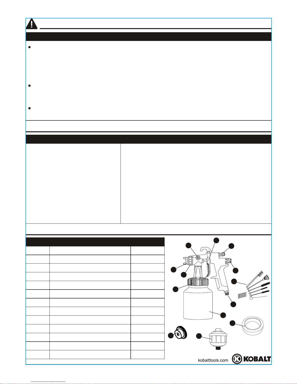
DESCRIPTION
Latex Spray Gun
Spray Gun Cleaning Kit
Spray Gun Filter
Masking Tape
Air cap (external mix)
Pattern Control Knob
Fluid Control Knob
Side Knob
Air Inlet
Air Cap Ring
Trigger
Canister
QUANTITY
1
1
1
1
1
1
1
1
1
1
1
1
PART
A
B
C
D
E
F
G
H
I
J
K
L
Air cap (internal mix)
1
M
B
C
D
A
E
F
G
H
I
J
K
L
M
Page 5
5
SPRAY GUN TERMS
Internal Mix
Process where the air and paint are mixed inside the air cap just before being
sprayed. This method is best for heavy bodied, slow drying paints and can only be
used with the pressure feed method. Do not use fast drying latex paints with internal
mix. The paint will dry inside and quickly clog the air cap.
External Mix
Process where the air and paint are mixed just after leaving the nozzle. This type of
mix should be used for fast drying latex paint and when a high quality finish is needed.
Pressure Feed
Method of material feed where a canister or paint tank is pressurized to force material
to the gun. Either internal or external mix air caps are used with this method. Pressure
feed is generally used for heavy bodied latex paints or for larger size projects.
Siphon Feed
Method of material feed where atmospheric pressure creates a partial vacuum to
siphon material to the gun. Only external mix air caps are used with this method.
Siphon feed is used with light bodied latex paints.
Bleeder
In this mode, air passes continuously through the gun whether spraying or not. This
mode is generally used when the
air is supplied by a continuously running air
compressor without tank.
Non-Bleeder
In this mode, air flows only when the trigger is pulled. This type of operation is
used with an air compressor equipped with a tank or with a large factory air system.
Do not use with a continuously running air compressor that does not have a tank.
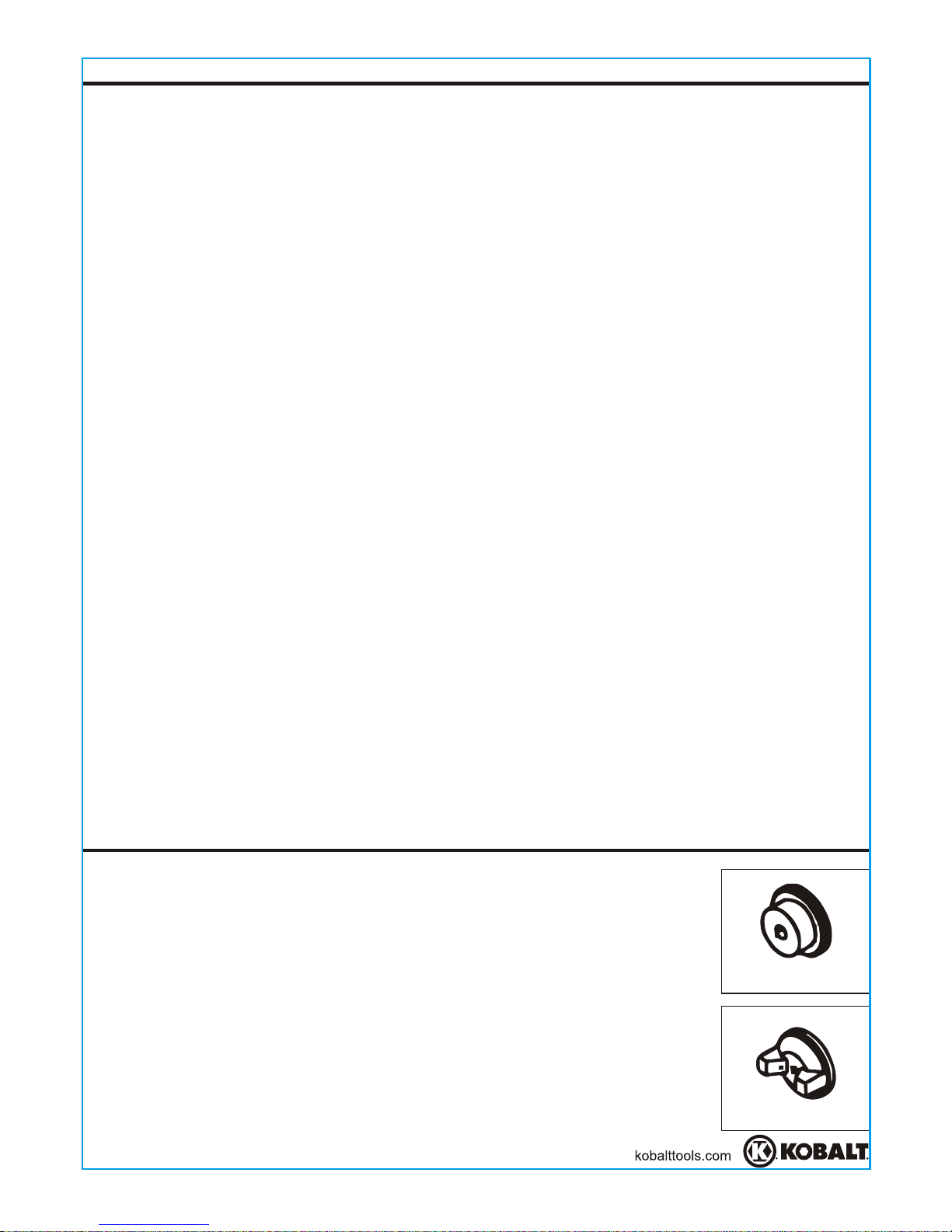
Use of Air Caps
Internal Mix - Generally used with slow drying, heavy bodied latex
paints and for faster material application. NOT to be used with fast
drying latex paints which will clog the opening in the air cap. Internal
mix caps must be used with pressure feed operation.
External Mix - Used for quick drying, light bodied latex paints. Better
for fine finish work. These caps can be used with either siphon or
pressure feed.
SPRAY GUN SET-UP
Internal mix air cap
external mix air cap
Page 6
Air Valve Spring
Pattern Control
Knob
Fluid
Control
Knob
Fluid Needle
Spring
Change of Feed Method
This latex spray gun is capable of pressure or
siphon feed. The feed method can be easily
changed by fully turning the side knob. You should
be sure before using the desired feed method.
(See Figure 1)
SPRAY GUN SET-UP
P: Pressure feed
S: Siphon feed
P
S
1
2
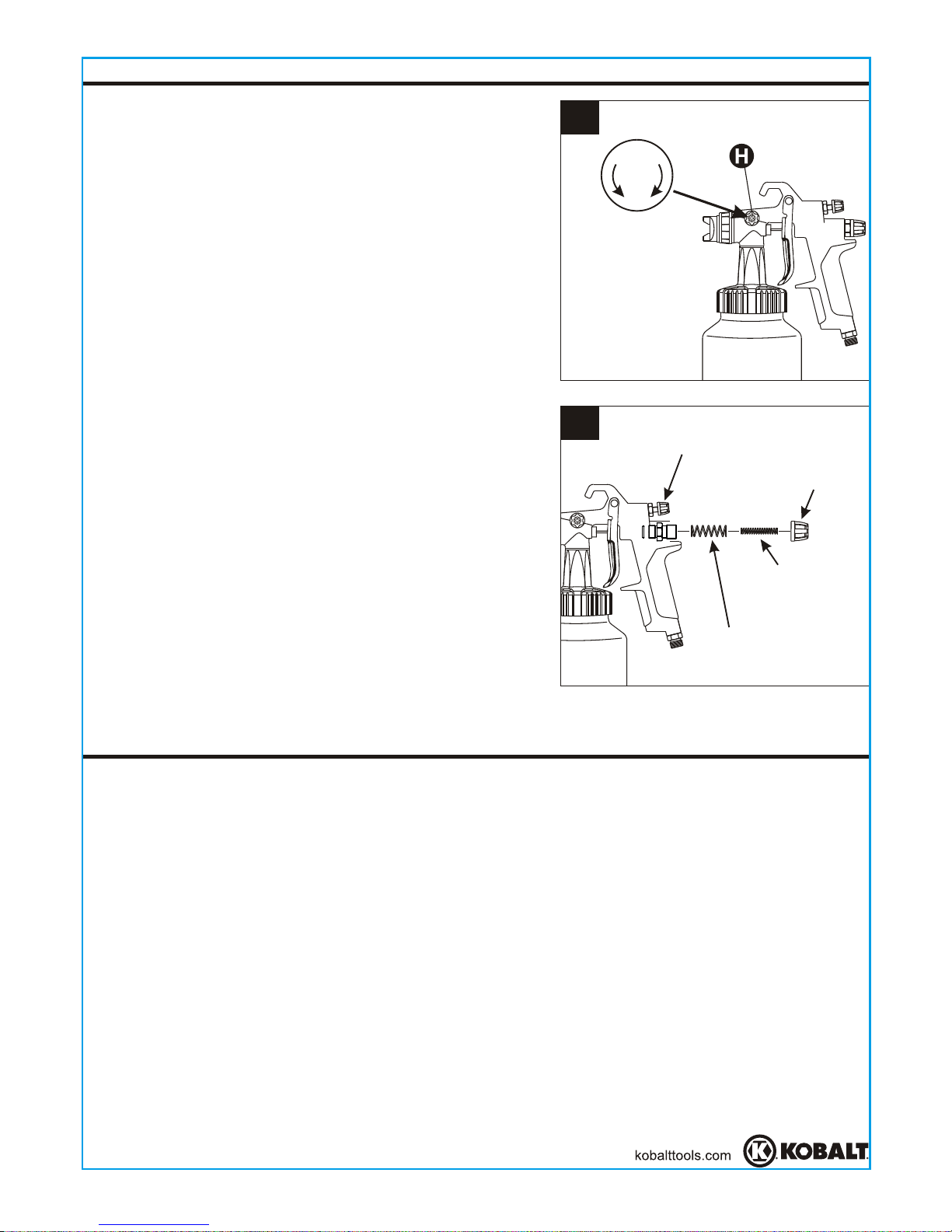
Non-Bleeder to Bleeder Conversion
(See Figure 2)
1. Remove spray gun from air supply.
2. Remove fluid control knob and the fluid needle
spring.
3. Remove air valve spring and store it in a safe
place so it can be replaced when necessary to
convert back to a non-bleeder type arrangement.
4. Insert fluid needle spring and replace fluid
control knob.
Before beginning assembly ofproduct, make sure allparts are present. Compare
parts with package contents list. Ifany part is missing ordamaged,do notattemptto
assemble the product. Contactcustomerservice forreplacementparts.
EstimatedAssembly Time:5-10 minutes
Tools Required forAssembly (notincluded):Adjustable wrench
PREPARATION
6
Page 7
ASSEMBLY INSTRUCTIONS
7
2
1
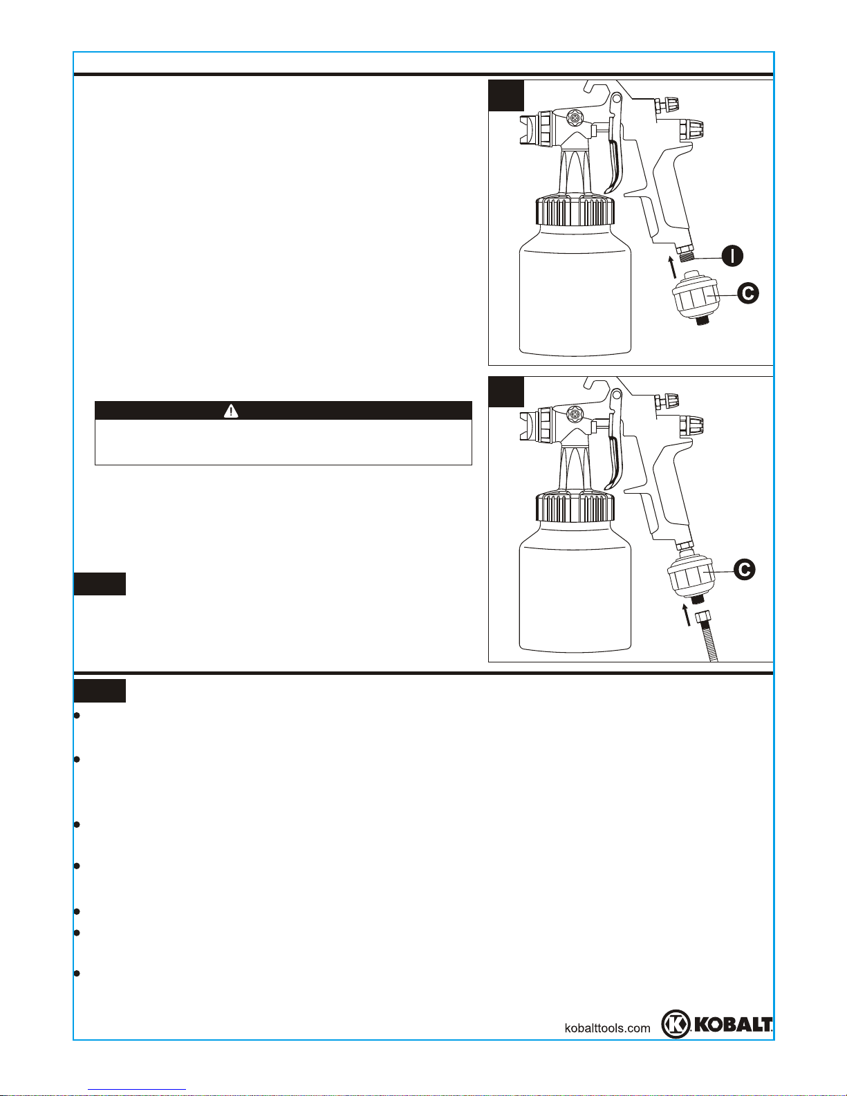
1. Mount the spray gun filter (C) with hand onto
the air inlet (I) of spray gun by connecting the
female threads of filter (C) with the male
threads of air inlet (I). Use thread sealant tape
(not provided) for airtight connection.
(See Figure 1)
2. Connect air hose with the male threads of the
filter (C). Use thread sealant tape (not
provided) for airtight connection. (See Figure 2)
NOTE The working pressure refers to the air line
pressure when the spray gun trigger (K) is pulled
fully under working conditions.
3. Set the working pressure to 30-50 psi
depending on the amount of fluid flow and
atomization as required. Do not exceed spray
gun maximum pressure.
Do not overtighten when connecting the filter
(C) with spray gun air inlet (I) and with air hose.
WARNING
OPERATING INSTRUCTIONS
NOTE
Before using desired paint in the spray gun, spray a compatible thinner or solvent
through the gun to remove any contaminants and residues.
Thin latex paints properly in accordance with the paint manufacturer's instructions
before spraying. If paint can not be thinned, the paint should not be used in
the sprayer.
Before adding paint, make sure all thinner or solvents are removed from the
spray canister.
that if any paint spills you can easily collect the paint to properly discard.
Its recommended to place drop cloth or other collection device under canister so
Fill the canister (L) about 3/4 full and start the air compressor.
Set up a piece of cardboard or other scrap material to use as as a target and
adjust for best spray pattern.
Test the consistency of the paint by making a few strokes on a cardboard target. If
paint still appears too thick, add a small amount of thinner. Do not exceed paint
manufacturer's thinning recommendations.
Page 8
Air Cap
Air Cap Ring
Horizontal Fan
Vertical Fan
1
2
3
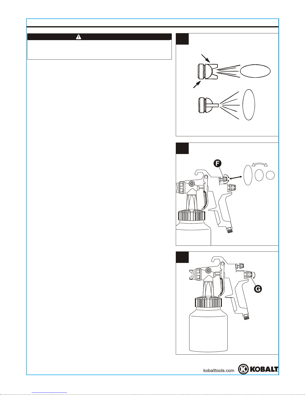
1. Adjust the direction of fan to be either horizontal
or vertical as required by loosening the air cap
ring (J) 90 degrees. Hand tighten the air cap
ring (J) after adjustment. (See Figure 1)
OPERATING INSTRUCTIONS
2. Set pattern size for desired shape. For full
pattern, open pattern control knob (F) by turning
counterclockwise. For a round pattern, turn
pattern control knob (F) clockwise.
(See Figure 2)
3. Turn the fluid control knob (G) fully clockwise
until closed. (See Figure 3)
8
The paint sprayer will not properly spray unless
the fan direction is either horizontal or vertical.
WARNING
Page 9
Paint too fine
Correct
Paint too coarse
Pattern Consistency (Atomization)
6-9 in.
Thin coat Heavy coat Thin coat
4
5
6
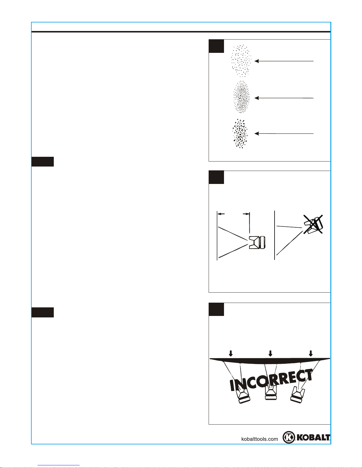
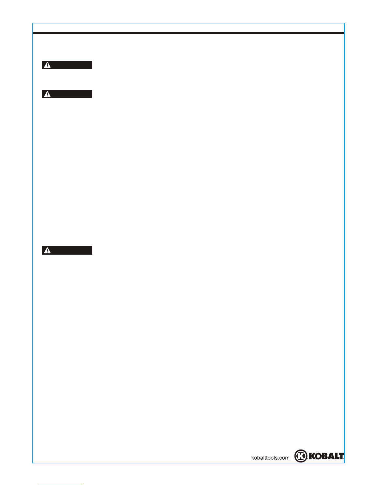
4. With gun 6-9 in. away from workpiece, spray a
short burst while turning the fluid knob
counterclockwise. Observe the spray pattern on
the workpiece and adjust the fluid control knob (G)
until desired pattern/atomization is obtained. If the
spray is too fine, which is caused by too much air
from the amount of paint being sprayed, reduce
the air pressure or open the fluid control knob (G)
to spray more paint. If the spray is too coarse/
spitting blobs, reduce the amount of paint with
the fluid control knob (G) or thin the paint more.
(See Figure 4)
OPERATING INSTRUCTIONS
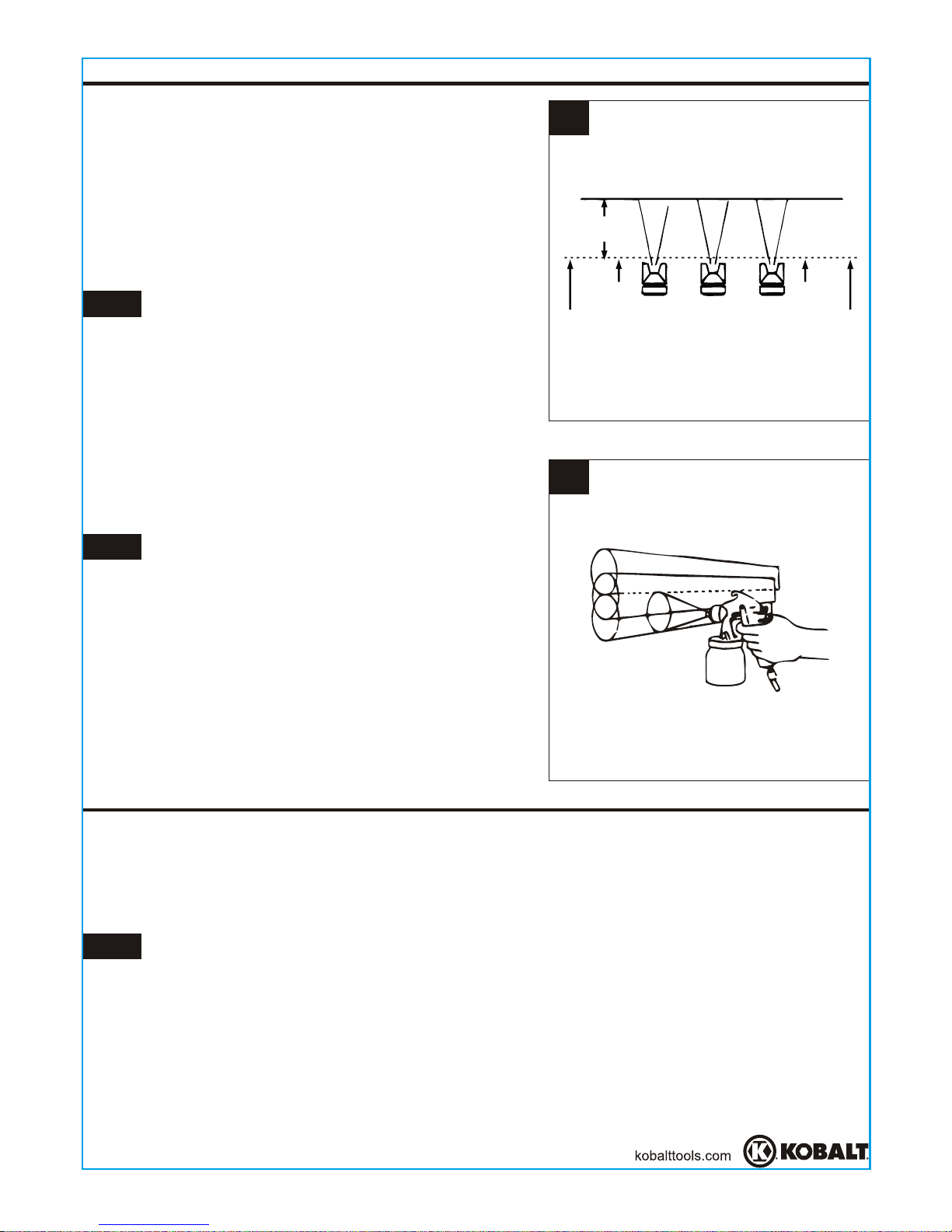
5. Keep the gun at the right angle as shown while
spraying. (See Figure 5)
NOTE The fluid control knob (G) can be adjusted
either clockwise or counterclockwise to finely
adjust pattern consistency. Before spraying on
workpiece, practice a few minutes on a cardboard
target to ensure that the pattern size and
consistency are set correctly.
NOTE Always keep the gun in motion while
spraying. Stopping gun movement in mid-stroke
will cause a build-up of paint and will result in runs.
Do not fan the gun from side to side while painting.
This will cause a build-up of paint in the center of
stroke and an insufficient coating at each end.
(See Figure 6)
9
Page 10
6-9 in.
Pull
Trigger
Start Stroke
Release
Trigger
End Stroke
7
8
6. Trigger the gun properly. Start the gun moving
at the beginning of the stroke before squeezing
the trigger (K) and release the trigger (K) before
stopping gun movement at the end of the stroke.
This procedure will feather/blend each stroke
with the next without showing overlap or
unevenness. (See Figure 7)
OPERATING INSTRUCTIONS
7. Overlap strokes just enough to obtain an even
coat. (See Figure 8)
8. Use a piece of cardboard as a shield to catch
overspray at the edges of workpiece to protect
other surfaces. Use masking tape (D) to cover
other areas if needed.
NOTE The amount of paint being applied can be
varied by the speed of stroke, distance from
workpiece and adjustment of the fluid control knob
(G). If speed of stroke is too slow, paint will be wet
on workpiece and may run. If speed of stroke is too
fast, paint will be dry and uneven on workpiece.
NOTE Two thin coats of paint will yield better
spraying results and have less chance of runs than
one heavy layer.
10
CARE AND MAINTENANCE
Local codes may require specific cleaning methods and equipment. Follow local
codes and manufacturer's recommendations for the use and disposal of spray paints
and solvent.
Daily Clean-Up
NOTE Clean spray gun immediately after use. Paint and other materials dry quickly in
the small passages rendering gun useless due to the difficulty of removing hardened
paint from the passages inside the gun.
1. Remove and empty the canister; then rinse with a solvent recommended for
the paint.
2. Refill canister with clean solvent and attach to the gun. Spray solvent through the
gun while shaking the gun vigorously. Wipe the gun exterior with a solvent-soaked
rag. Repeat until the gun is clean.
Page 11
CARE AND MAINTENANCE
3. Remove the air cap and soak in solvent until clean. Use a small brush for stubborn
stains if necessary. Toothpicks or small brushes may be used to clean air passages.
Never use metal objects to clean precisely drilled passages.
Damaged passages will cause improper spraying.
4. Clean gaskets with a solvent soaked rag.
Never immerse gaskets or spray gun body in solvents to prevent
equipment damage.
5. After using water to clean out spray gun, spray mineral spirits through the gun to
prevent corrosion.
6. Clean and flush gun thoroughly to neutralize any contaminants corrosive to the
spray gun.
7. Use a non-silicone oil on all moving parts when reassembling. Use Vaseline® or
light grease on all threaded connections prior to storage.
WARNING
WARNING
Periodic Clean-Up
Due to improper cleaning and paint it may be necessary to inspect and clean the
internal parts and the gun body.
1. Examine openings in air cap and fluid tip. If clogged, remove any o-rings and soak
the air cap or fluid tip in solvent.
2. A brush, toothpick or something similar may be used to dislodge the dried paint
from holes and passages.
Never use metal objects to clean precisely drilled passages.
Damaged passages will cause improper spraying.
3. Remove and check fluid needle for excessive wear at the tip and straightness.
IMPORTANT: If the needle tip is worn more on one side than the other, either the
needle is bent or the gun body has been dropped or knocked out-of-line. There are
no adjustments that can be made to a bent gun body. Test the needle by rolling on
a flat surface. Replace if necessary.
4. Check and replace any damaged o-rings and seals. O-rings and seals can be
wiped clean but not be soaked in solvent.
5. Unscrew packing nuts and replace the packing only if a leak will not stop when the
nut is tightened. Do not overtighten
a packing nut because this will restrict
movement of the needle.
6. Re-assemble in reverse order of above and use a non-silicone oil on moving parts.
Apply Vaseline® or light grease on threaded joints and hose connections.
WARNING
Storing
1. When not using spray gun, turn the fluid adjustment knob counterclockwise to open
which will reduce spring tension on needle fluid tip.
2. Spray gun must be well cleaned and lightly lubricated.
3. Store spray gun in a dry and safe place out of reach of children.
11
Page 12
12
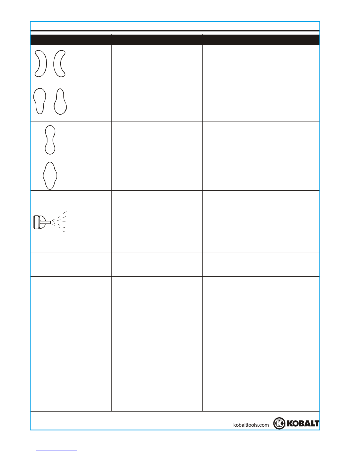
PROBLEM
TROUBLESHOOTING
CORRECTIVE ACTIONPOSSIBLE CAUSE
Right or left
heavy spray
pattern
Top or bottom
heavy spray
pattern
Split spray
pattern
Center
heavy spray
pattern
Sputtering
spray
Fluid leaking from
packing nut
Air leaking from air cap
without pulling trigger
Excessive overspray
Will not spray
1. Holes in left or right side of
the air cap are plugged
2. Dirt on left or right side of
fluid tip
1. Dried material at top or
bottom of fluid tip
2. Loose air cap or dirty seat
3. Air cap plugged
1. Fan pattern open too far
2. Fluid adjustment turned in
too far
3. Atomization air too high
1. Fan adjustment partially
closed
2. Material too thick
3.Atomization pressure too low
1. Material level too low
2. Container tipped too far
3. Loose fluid inlet connection
4. Loose or damaged fluid
tip/seat
5. Dry or loose fluid needle
packing nut
6. Air vent clogged
1. Packing nut loose
2. Packing worn or dry
1. Sticking air valve stem
2. Contaminate on air valve
or seat
3. Worn or damaged air valve
or seat
4. Broken air valve spring
5. Bent valve stem
1. Too high atomization
pressure
2. Too far from work surface
3. Improper stroking (arcing,
gun motion too fast)
1. No pressure in gun
2. Fluid control not open
enough
3. Fluid too heavy
1. Clean using only a non-metallic pick
2. Clean
1. Clean
2. Clean and tighten
3. Clean using only a non-metallic pick
1. Partially close the pattern adjustment
2. Open fluid adjustment
3. Reduce atomization air pressure
1. Open fan pattern adjustment
2. Thin to proper viscosity
3. Increase atomization pressure
1. Refill
2. Hold more upright
3. Tighten
4. Adjust or replace
5. Lubricate and or tighten
6. Clear vent hole
1. Tighten, but do not restrict, needle
2. Replace or lubricate (non-silicone oil)
1. Lubricate
2. Clean
3. Replace
4. Replace
5. Replace
1. Reduce pressure
2. Adjust to proper distance
3. Move at moderate pace, parallel to
surface
1. Check air lines
2. Open fluid control
3. Thin fluid or change to pressure feed
system
Page 13
THREE-YEAR LIMITED WARRANTY
13
This tool is warranted by the manufacturer to the original purchaser from the original
purchase date for three (3) years subject to the warranty coverage described herein.
This tool is warranted to the original user to be free from defect in material and
workmanship. If you believe that a tool is defective, return the tool, with proper proof
of purchase to the point of purchase. If it is determined that the tool is defective and
covered by this warranty, the distributor will replace the tool or refund the
purchase price.
This warranty is void if: defects in materials or workmanship or damages result from
repairs or alterations which have been made or attempted by others or the
unauthorized use of nonconforming parts; the damage is due to normal wear,
damage is due to abuse (including overloading of the tool beyond capacity), improper
maintenance, neglect or accident; or the damage is due to the use of the tool after
partial failure or use with improper accessories or unauthorized repair or alteration.
This warranty gives you specific legal rights, and you may also have other rights that
vary from state to state.
For warranty questions, call our customer service department at 1-888-3KOBALT,
8:00 a.m.-8:00 p.m. EST, Monday-Friday.
Page 14
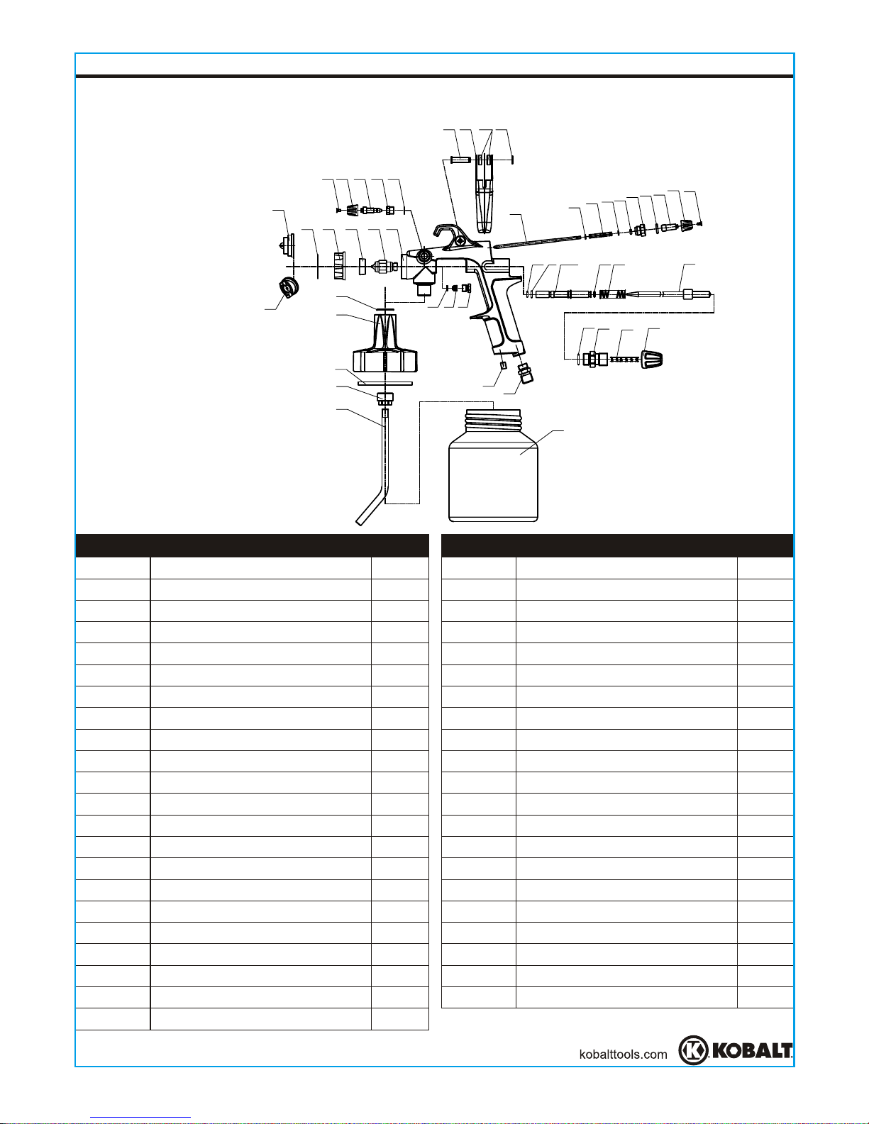
REPLACEMENT PARTS LIST
Printed in China
14
For replacement parts, call our customer service department at 1-888-3KOBALT,
8:00 a.m.-8:00 p.m., EST, Monday-Friday.
23
24
25
26
27
28
29
30
31
G
I
34
35
36
37
38
A
40
41
42
Air cap (external mix)
Air cap (internal mix)
Air cap seal
Air cup ring
Air separating ring
Fluid nozzle
Gun body
Phillips Screw
Side knob
Air adjusting valve
Air adjusting seat
Snap Retainer
Trigger pin
Trigger
Washer
Snap retaining ring (E-ring)
Pattern control needle
Retaining ring
Pattern control spring
O-ring 2.5 × 2.1
Pattern control seat
Pattern control screw
O-ring 4.5 × 1.8
O-ring 5.2 × 1.9
Fluid needle seat
Air valve spring
Fluid needle
O-ring 10 × 1.8
Fluid needle adjusting seat
Fluid needle spring
Fluid control knob
Air inlet
Seal nut
Packing nut
Sealing washer
Washer
O-ring 19 × 1.8
Canister top
Canister gasket
Retaining nut
Material tube
E
M
3
J
5
6
7
8
H
10
12
11
13
K
15
16
17
18
19
20
21
1
1
1
1
1
1
1
2
2
1
1
1
1
1
1
1
1
2
1
1
1
O-ring 9 × 1.8
22
1
1
2
1
1
1
1
1
1
1
1
1
1
1
1
1
1
1
1
1
1
L
Canister
1
Part No.
Description Qty.
Part No.
Description Qty.
E
M
3 J 5
88HH10 11 12
13 K 15 16
17
18
19
24
24 27
29
30
31 G
I
34
L
353637
38
40
41
42
A
28
25 26
18
20
21
22
23
6 7
Page 15

ARTICLE #0220964
MODÈLE #SGY-AIR70TZ
JOIGNEZ VOTRE REÇU ICI
Numéro de série Date d'achat
15
KOBALT® et le motif de K® sont des marques
de commerce déposées de LF, LLC. Tous droits
réservés.
Des questions, des problèmes, des pièces manquantes? Avant de
retourner l'article au détaillant, communiquez avec notre service à la
clientèle au 1 888 3KOBALT, entre 8 h et 20 h (HNE), du lundi au vendredi.
ENSEMBLE DE
PISTOLET DE
PULVÉRISATION
POUR LATEX
Page 16

TABLE DES MATIÈRES
16
Consignes de sécurité ....................................................................................... 17
Contenu de l'emballage ..................................................................................... 19
Préparation ........................................................................................................ 21
Instructions pour l'assemblage .......................................................................... 21
Mode d'emploi ................................................................................................... 22
Entretien ........................................................................................................... 25
Dépannage ....................................................................................................... 27
Garantie ............................................................................................................ 28
Liste des pièces de rechange ........................................................................... 29
Page 17

17
CONSIGNES DE SÉCURITÉ
Assurez-vous de lire et de comprendre l'intégralité de ce manuel avant de tenter
d'assembler, d'utiliser ou d'installer le produit. Si vous avez des questions concernant ce
produit, veuillez appeler notre service à la clientèle au 1 888 3KOBALT, entre 8 h et 20 h
(HNE), du lundi au vendredi.
Veuillez suivre tous les codes d'électricité et de sécurité de votre région ainsi que le
Code canadien de l'électricité et la Loi sur la santé et la sécurité du travail.
Au moment de la pulvérisation et du nettoyage, suivez les directives du manuel et
respectez les mesures de sécurité du fabricant. (Reportez-vous à la fiche signalétique
du produit [FS].)
N'utilisez pas ce produit si d'autres personnes (notamment des enfants) ou des
animaux se trouvent dans l'aire de travail.
Travaillez toujours dans un endroit propre. Pour éviter tout risque de blessure et de
dommage à la pièce, ne pulvérisez jamais sur une surface poussiéreuse ou
encombrée de débris.
Utilisez toujours un régulateur de pression pour l'alimentation en air du pistolet de
pulvérisation.
AVERTISSEMENT
N'utilisez jamais le produit s'il a été endommagé pendant la manutention, le transport
ou l'utilisation. Un produit endommagé pourrait éclater et, par conséquent, causer des
blessures et des dommages matériels.
Portez un masque facial ou un masque anti-vapeurs ainsi que des vêtements de
protection pendant la pulvérisation. Utilisez toujours le pistolet de pulvérisation dans
un endroit bien aéré afin de prévenir les risques d'incendie et les dangers pour la santé.
Pour de plus amples renseignements, consultez la fiche signalétique (FS) du pistolet.
Ne pulvérisez jamais de matières inflammables à proximité d'une flamme nue ou d'une
source d'inflammation. N'entreposez jamais de liquides ou de gaz inflammables à
proximité du compresseur.
Ne pulvérisez pas de l'acide, des matières corrosives, des produits chimiques toxiques,
des fertilisants ou des pesticides.
L'utilisation de ces matières peut causer de graves blessures, voire entraîner la mort.
Si vos yeux ou toute autre partie de votre visage entre en contact direct avec la matière
pulvérisée, communiquez avec un médecin ou une salle d’urgence pour obtenir de
l’aide immédiate.
N’excédez pas la pression de fonctionnement des pièces (p. ex., tuyaux et raccords)
de l’outil de peinture.
Conservez un bon équilibre en tout temps. Ne vous étirez pas pour étendre votre
portée, ce qui pourrait vous faire glisser, basculer ou tomber et causer des blessures
graves, voire mortelles. Prenez garde à l’excédent de tuyau laissé dans l’aire de travail
ou sur la surface de travail. Ne faites pas un usage abusif des tuyaux ou des raccords.
Ne transportez jamais l’outil par son tuyau et ne tirez jamais sur le tuyau pour le
débrancher de la source d’alimentation. Tenez les tuyaux éloignés des sources de
chaleur, de l’huile et des objets coupants. Vérifiez l’état des tuyaux avant chaque
utilisation et assurez-vous que tous les raccords sont solides.
Certaines matières pouvant être utilisées avec l’outil risquent de causer des irritations
cutanées si elles entrent en contact direct avec la peau. Lisez l’étiquette ou la fiche
signalétique des matières que vous prévoyez utiliser afin de savoir si elles peuvent
provoquer de telles irritations.
Page 18

REMARQUE
Ce pistolet de pulvérisation est conçu pour la maison, la ferme et les commerces.
Il peut contenir tout type de peinture au latex. Il peut facilement et rapidement
être converti de non purgeur à purgeur, d'un pistolet à pression à un pistolet à
siphon et d'un pistolet à mélange interne à un pistolet à mélange externe, et vice
versa. Il comprend également une commande de réglage du jet. Il peut aussi
être utilisé avec un autre réservoir sous pression.
La pression de pulvérisation est déterminée par le régulateur de la source
d'alimentation en air. Le bouton de réglage du fluide, la viscosité de la peinture
et la pression d'air permettent de régler la quantité de fluide pulvérisée.
Si vous ne nettoyez pas adéquatement la pièce après chaque utilisation, vous
risquez d’endommager le produit.
CONSIGNES DE SÉCURITÉ
CARACTÉRISTIQUES
À PRESSION/À SIPHON
INTERNE/EXTERNE
PURGEUR/NON PURGEUR
1,4 MM (0,055 PO)
2
2
50 LB/PO
3,5 EN MOYENNE/8,6 EN CONTINU
2
21,66 CM (8 PO) À 50 LB/PO /À 21,66 CM
(8 PO) DE LA PIÈCE
1/4 PO NPS (M)
3/8 PO NPS (M)
COMPOSANT
TYPE D'ALIMENTATION
TYPE DE MÉLANGE
TYPE DE PURGE
DIAMÈTRE INTÉRIEUR DE
LA BUSE À PEINTURE
PRESSION DE SERVICE MAXIMALE
40 À 50 LB/PO
PRESSION DE SERVICE
AIR REQUIS (PI /MIN À 50 LB/PO )
2
3
LARGEUR DU JET
ENTRÉE D'AIR
ENTRÉE DE FLUIDE
CARACTÉRISTIQUES DU PRODUIT
18
AVERTISSEMENT
LES RISQUES LIÉS À L’EXPOSITION À CES PRODUITS VARIENT SELON LE
NOMBRE DE FOIS OÙ VOUS PRATIQUEZ CES ACTIVITÉS. AFIN DE LIMITER
VOTRE EXPOSITION À CES PRODUITS CHIMIQUES, TRAVAILLEZ DANS UN
ENDROIT BIEN VENTILÉ ET UTILISEZ DE L’ÉQUIPEMENT DE SÉCURITÉ
APPROUVÉ, TEL QU’UN MASQUE ANTIPOUSSIÈRE CONÇU SPÉCIALEMENT
POUR FILTRER LES PARTICULES MICROSCOPIQUES.
DANGER
Ne pulvérisez jamais de peinture à
moins de 8 m du compresseur. Si c'est
possible, placez le compresseur dans
une autre pièce.
MISE EN GARDE
Gardez le tuyau loin des objets
tranchants. Vous risquez de subir de
graves blessures si vous percez le tuyau
à air. Examinez le tuyau à air
régulièrement et remplacez-le s'il est
endommagé ou rompu.
Page 19

CONTENU DE L'EMBALLAGE
DESCRIPTION
Pistolet de pulvérisation
pour latex
Trousse pour le nettoyage
du pistolet de pulvérisation
Filtre pour pistolet de
pulvérisation
Ruban-cache
Obturateur d’air
(mélange externe)
Bouton de réglage du jet
Bouton de réglage du fluide
Bouton latéral
Entrée d'air
Anneau de l'obturateur d'air
Gâchette
Réservoir
QUANTITÉ
1
1
1
1
1
1
1
1
1
1
1
1
PIÈCE
A
B
C
D
E
F
G
H
I
J
K
L
Obturateur d’air
(mélange interne)
1
M
TERMES RELATIFS AU PISTOLET DE PULVÉRISATION
Mélange interne
Procédé au cours duquel l'air et la peinture sont mélangés dans l'obturateur d'air,
juste avant que le fluide soit pulvérisé. Ce procédé convient aux peintures épaisses à
séchage lent et ne peut être utilisé qu'en mode d'alimentation sous pression. Ne
l'utilisez pas pour une peinture au latex à séchage rapide, car celle-ci sécherait à
l'intérieur et bloquerait rapidement l'obturateur d'air.
Mélange externe
Procédé au cours duquel l'air et la peinture sont mélangés dès qu'ils sont expulsés de
la buse. Ce procédé s'utilise pour les peintures à séchage rapide. Il doit également
être employé lorsqu'il est nécessaire d'obtenir une finition de qualité supérieure.
Alimentation sous pression
Procédé d'alimentation au cours duquel le réservoir de peinture est mis sous pression
de manière à pousser le fluide jusqu'au pistolet. Ce procédé peut être utilisé avec un
obturateur d'air pour mélange interne et mélange externe. On s'en sert généralement
pour les peintures au latex épaisses ou dans des projets à grande échelle.
19
B
A
E
F
G
H
I
J
K
L
C
D
M
Page 20

TERMES RELATIFS AU PISTOLET DE PULVÉRISATION
Utilisation d'un obturateur d'air
Mélange interne - Généralement utilisé pour les peintures au latex
épaisses à séchage lent ou pour une application rapide. N'UTILISEZ
PAS ce type de mélange avec une peinture au latex à séchage
rapide, car elle bloquerait l'ouverture de l'obturateur d'air. Le mode
d'alimentation sous pression doit être utilisé avec les obturateurs
d'air pour mélange interne.
Mélange externe - Utilisé pour les peintures au latex fluides à
séchage rapide. Idéal pour les travaux de finition de qualité. Le
mode d'alimentation sous pression ou à siphon peut être utilisé avec
les obturateurs d'air pour mélange externe.
ASSEMBLAGE DU PISTOLET DE PULVÉRISATION
Obturateur d'air pour
mélange interne
Obturateur d'air pour
mélange externe
Alimentation à siphon
Procédé d'alimentation au cours duquel la pression atmosphérique crée un vide partiel
qui permet de siphonner le fluide jusqu'au pistolet. Ce procédé ne peut être utilisé
qu'avec un obturateur d'air pour mélange externe. L'alimentation à siphon est
employée avec les peintures en latex fluides.
Purgeur
Dans ce mode, l'air passe continuellement dans le pistolet, que vous pulvérisiez ou
non de la peinture. Il est généralement utilisé lorsque l'air provient d'un compresseur
d'air sans réservoir qui fonctionne continuellement.
Non purgeur
Dans ce mode, l'air passe seulement lorsqu'on tire la gâchette. Ce procédé est utilisé
avec un compresseur d'air muni d'un réservoir ou un gros système de production d'air.
Ne l'utilisez pas avec un compresseur d'air sans réservoir qui fonctionne
continuellement.
Changement du mode d'alimentation
Le mode d'alimentation du pistolet de pulvérisation
pour latex peut être sous pression ou à siphon.
Vous pouvez facilement changer le mode
d'alimentation en tournant complètement le bouton
latéral. Soyez certain du mode choisi avant
l'utilisation. (Consultez la figure 1.)
P
S
P : Alimentation
sous pression
S : Alimentation à
siphon
1
20
Page 21

Conversion de non purgeur à purgeur
(Consultez la figure 2.)
1. Séparez le pistolet de l'alimentation en air.
2. Retirez le bouton de réglage du fluide et le
ressort du pointeau du fluide.
3. Pour revenir au type non purgeur, retirez le
ressort du reniflard et rangez-le dans un endroit
sûr pour que vous puissiez le remettre lorsque
cela sera nécessaire.
4. Insérez le ressort du pointeau du fluide, puis
replacez le bouton de réglage du fluide.
Avant de commencer l'assemblage du produit, assurez-vous d'avoir toutes les pièces.
Comparez les pièces dans l'emballage avec la liste des pièces. S'il y a des pièces
manquantes ou endommagées, ne tentez pas d'assembler le produit. Communiquez
avec le service à la clientèle pour obtenir des pièces de rechange.
Temps d'assemblage approximatif : de 5 à 10 minutes.
Outils nécessairespourl'assemblage (non inclus): clé à molette.
PRÉPARATION
ASSEMBLAGE DU PISTOLET DE PULVÉRISATION
INSTRUCTIONS POUR L'ASSEMBLAGE
1
1. Fixez manuellement le filtre (C) à l'entrée d'air
du pistolet (I) en assemblant l'extrémité filetée
femelle du filtre (C) et l'extrémité filetée mâle
de l'entrée d'air (I). Utilisez du ruban
d'étanchéité (non fourni) pour que l'assemblage
soit étanche à l'air. (Consultez la figure 1.)
21
Bouton de
réglage du
fluide
Ressort du reniflard
Ressort du
pointeau du
fluide
Bouton de réglage
du jet
2
Page 22

2
2. Branchez le tuyau à air sur l'extrémité filetée
mâle du filtre (C). Utilisez du ruban d'étanchéité
(non fourni) pour que l'assemblage soit étanche
à l'air. (Consultez la figure 2.)
REMARQUE La pression de service correspond à
la pression dans la conduite d'air quand la gâchette
du pistolet de pulvérisation (K) est complètement tirée.
3. Réglez la pression de service entre 30 et
2
50 lb/po , selon le débit voulu. N'excédez pas la
pression maximale du pistolet de pulvérisation.
Évitez de serrer excessivement lors de la
fixation du filtre (C) à l'entrée d'air (I) du pistolet
de pulvérisation et au tuyau à air.
AVERTISSEMENT
MODE D'EMPLOI
REMARQUE
Avant d'utiliser la peinture souhaitée dans le pistolet, pulvérisez un diluant ou un
solvant compatible afin d'éliminer tous les contaminants et résidus.
Diluez correctement la peinture au latex, conformément aux instructions du
fabricant, avant de la pulvériser. S'il n'est pas possible de diluer la peinture, celle-ci
ne doit pas être utilisée avec le pistolet.
Nous vous recommandons de placer une toile de protection ou tout autre dispositif
récepteur sous le réservoir afin de pouvoir facilement ramasser et jeter la peinture
si vous en renversez.
Utilisez un morceau de carton ou tout autre matériel mis au rebut comme cible afin
de régler le jet.
Vérifiez la consistance de la peinture en effectuant quelques pulvérisations sur le
morceau de carton. Si la peinture semble encore trop épaisse, ajoutez un peu de
diluant. Suivez les recommandations du fabricant de la peinture en ce qui a trait à
l'utilisation de diluant.
Remplissez environ les trois quarts du réservoir (L), puis démarrez le compresseur
d'air.
Avant d’ajouter de la peinture, assurez-vous de retirer tous les diluants et solvants
du réservoir.
INSTRUCTIONS POUR L'ASSEMBLAGE
22
Page 23

MODE D'EMPLOI
Obturateur d'air
Anneau de
l'obturateur d'air
Jet en éventail
horizontal
Jet en éventail
vertical
1
2
3
1. Réglez l'orientation (horizontale ou verticale) du
jet en éventail en dévissant l'anneau de
l'obturateur d'air de 90 degrés (J). Vissez
manuellement l'anneau (J) après le réglage.
(Consultez la figure 1.)
2. Réglez le jet à la forme voulue. Pour un jet
complet, tournez le bouton de réglage du jet (F)
dans le sens contraire des aiguilles d'une
montre. Pour un jet de forme ronde, tournez le
bouton de réglage du jet (F) dans le sens des
aiguilles d'une montre. (Consultez la figure 2.)
3. Tournez jusqu'au bout le bouton de réglage du
fluide (G), dans le sens des aiguilles d'une
montre. (Consultez la figure 3.)
23
Le pistolet à peinture ne fonctionnera
correctement que si l’orientation du jet en éventail
est horizontale ou verticale.
AVERTISSEMENT
Page 24

24
Jet trop fin
Jet adéquat
Jet trop épais
Consistance du jet (pulvérisation)
15 à
23 cm
Couche
mince
Couche
épaisse
Couche
mince
INADEQUAT
4
5
6
4. En tenant le pistolet à une distance de 15 à
23 cm de la pièce, pulvérisez un jet court tout en
tournant le bouton de réglage du fluide dans le
sens contraire des aiguilles d'une montre.
Observez le jet sur la pièce et tournez le bouton
de réglage du fluide (G) jusqu'à ce que vous
obteniez la pulvérisation ou le jet souhaité. Si
le jet est trop fin, ce qui est causé par une trop
grande quantité d'air présente dans la peinture
pulvérisée, réduisez la pression d'air ou tournez
le bouton de réglage du fluide (G) pour pulvériser
plus de peinture. Si le jet est trop épais ou si le
pistolet projette de grosses gouttes, réduisez la
quantité de peinture à l'aide du bouton de réglage
du fluide (G) ou diluez davantage la peinture.
(Consultez la figure 4.)
5. Maintenez le pistolet au bon angle pendant que
vous pulvérisez le fluide. (Consultez la figure 5.)
REMARQUE Il est possible de
tourner le bouton
de réglage du fluide (G) dans un sens ou dans
l'autre pour obtenir la bonne consistance de jet.
Avant de pulvériser le fluide sur une pièce,
exercez-vous pendant quelques minutes sur un
morceau de carton pour vous assurer que la
largeur du jet et la consistance sont bien réglées.
REMARQUE Maintenez toujours le pistolet en
mouvement lorsque vous pulvérisez le fluide. Si
vous arrêtez de bouger pendant la pulvérisation,
de la peinture s'accumulera, ce qui pourrait
entraîner des coulures. Ne bougez pas la buse du
pistolet d'un côté à l'autre pendant que vous
peignez, sinon la peinture s'accumulera au centre
du jet et sera insuffisante à chaque extrémité.
(Consultez la figure 6.)
MODE D'EMPLOI
Page 25

Relâchement
de la gâchette
15 à
23 cm
Déclenchement
de la gâchette
Début du
mouvement
Fin du
mouvement
7
8
6. Appuyez correctement sur la gâchette. Amorcez
le mouvement du pistolet avant d'appuyer sur la
gâchette (K), et arrêtez-le après avoir relâché la
gâchette. Cette méthode produira un dégradé en
biseau ou uniformisera chaque jet, sans créer de
chevauchement ni d'irrégularités.
(Consultez la figure 7.)
7. Chevauchez chaque jet de manière à obtenir
une couche égale. (Consultez la figure 8.)
8. Afin d'éviter de pulvériser au-delà des bords
dela pièce ou pour protéger d'autres surfaces,
utilisez un morceau de carton comme écran de
protection; vous pouvez également utiliser du
ruban-cache (non fourni).
REMARQUE Deux minces couches de peinture
donneront de meilleurs résultats et risquent moins
d'entraîner des coulures qu'une couche épaisse.
ENTRETIEN
La réglementation locale peut exiger l'utilisation de méthodes et d'équipement de
nettoyage précis. Respectez la réglementation de votre région ainsi que les
recommandations du fabricant en ce qui a trait à l'utilisation et à l'élimination de
peintures à pulvériser et de solvants.
Nettoyage quotidien
REMARQUE Nettoyez le pistolet de pulvérisation immédiatement après l'avoir utilisé.
La peinture et les autres matières sèchent rapidement à l'intérieur du pistolet et sont
par la suite difficiles à déloger, ce qui peut rendre le pistolet inutilisable.
1. Retirez et videz le réservoir; rincez-le ensuite avec un solvant qui convient au type
de peinture.
2. Remplissez le réservoir d'un solvant propre, puis remettez-le en place. Pulvérisez du
solvant tout en agitant le pistolet vigoureusement. Essuyez le pistolet avec un linge qui
a été trempé dans un solvant. Répétez ces étapes jusqu'à ce que le pistolet soit propre.
MODE D'EMPLOI
REMARQUE La quantité de peinture appliquée
peut varier selon la vitesse du mouvement, la
distance entre vous et la pièce et le réglage du
fluide (G). Si la vitesse de mouvement est trop
lente, la peinture sera humide sur la pièce, ce qui
pourrait entraîner des coulures. Si la vitesse de
mouvement est trop rapide, la peinture sera sèche
et inégale sur la pièce.
25
Page 26

3. Retirez l'obturateur d'air et trempez-le dans le solvant jusqu'à ce qu'il soit propre.
Au besoin, utilisez une petite brosse pour éliminer les taches tenaces. Il est possi ble d'employer un cure-dent ou une petite brosse pour nettoyer les conduits d'air.
N'utilisez jamais d'objets en métal pour nettoyer les conduits
percés. Des conduits endommagés entraîneront une pulvérisation inadéquate.
4. Nettoyez les joints avec un linge qui a été trempé dans un solvant.
Ne trempez jamais les joints ou le corps du pistolet de
pulvérisation dans un solvant pour éviter de les endommager.
5. Après avoir nettoyé le pistolet avec de l'eau, remplissez-le d'essence minérale, puis
pulvérisez-la pour prévenir la corrosion.
6. Nettoyez soigneusement le pistolet et rincez-le abondamment afin de neutraliser
les contaminants corrosifs.
7. Enduisez toutes les pièces amovibles d'une huile sans silicone lorsque vous les
réassemblez. Enduisez tous les raccords filetés de Vaseline® ou d'un léger
lubrifiant avant d'entreposer l'outil.
AVERTISSEMENT
AVERTISSEMENT
Nettoyage périodique
Il peut être nécessaire d'inspecter et de nettoyer les pièces internes et le corps du
pistolet en raison d'un mauvais nettoyage ou de l'utilisation d'une peinture inadéquate.
1. Examinez les ouvertures de l'obturateur d'air et la buse. Si elles sont obstruées,
retirez le joint torique et trempez l'obturateur d'air ou la buse dans le solvant.
2. Il est possible d'utiliser un cure-dent, une brosse ou un objet semblable pour
déloger la peinture sèche des trous et des conduits.
N'utilisez jamais d'objets en métal pour nettoyer les conduits
percés. Des conduits endommagés entraîneront une pulvérisation inadéquate.
3. Retirez le pointeau du fluide pour vérifier qu'il est droit et que le bout ne présente
pas de traces d'usure excessive.
IMPORTANT : Si le bout du pointeau est plus usé d'un côté que de l'autre, soit le
pointeau est plié, soit le pistolet a été échappé ou a été frappé durement. Il est
impossible de réparer un corps de pistolet déformé. Vérifiez le pointeau en le
faisant rouler sur une surface plane. Remplacez-le si nécessaire.
4. Vérifiez les joints toriques et les joints d'étanchéité et remplacez ceux qui sont
endommagés. Vous pouvez les nettoyer avec un linge,
mais ne les trempez pas
dans un solvant.
5. Dévissez les écrous de presse-garniture et remplacez le presse-garniture
seulement si la fuite persiste après avoir vissé les écrous. Ne vissez pas
excessivement les écrous pour ne pas limiter le mouvement du pointeau.
6. Réassemblez les pièces dans l'ordre inverse et enduisez les pièces amovibles
d'une huile sans silicone. Enduisez tous les raccords de tuyaux et les joints filetés
de Vaseline® ou d'un léger lubrifiant.
AVERTISSEMENT
Entreposage
1. Lorsque vous n'utilisez pas le pistolet de pulvérisation, tournez le bouton de réglage
du fluide dans le sens contraire des aiguilles d'une montre afin de réduire la tension
du ressort sur le bout du pointeau du fluide.
2. Il faut bien nettoyer et légèrement lubrifier le pistolet de pulvérisation.
3. Rangez le pistolet de pulvérisation dans un endroit sec et sûr, hors de la portée des
enfants.
ENTRETIEN
26
Page 27

PROBLÈME
DÉPANNAGE
MESURE CORRECTIVECAUSE POSSIBLE
Gros jet vers
la gauche ou
la droite
Gros jet vers
le haut ou le
bas
Jet réduit au
centre
Gros jet au
centre
Pulvérisation
en gouttes
Fuite de fluide de l'écrou
de presse-garniture
Fuite d'air de l'obturateur
sans que la gâchette ait
été tirée
1. Vous avez trop tourné le
bouton de réglage du jet en
éventail.
2. Vous avez trop tourné le
bouton de réglage du fluide.
3. La pression d'air de
pulvérisation est trop élevée.
1. Le bouton de réglage du jet en
éventail est partiellement fermé.
2. Le fluide est trop épais.
3. La pression de pulvérisation est
trop basse.
1. Le niveau de fluide est trop
bas.
2. Le réservoir est trop renversé.
3. Le raccord d'entrée du
fluide est dévissé.
4. Le régulateur ou la buse est
endommagé ou dévissé.
5. Un écrou de presse garniture du pointeau du
fluide est dévissé ou sec.
6. L'évent d'aération est obstrué.
1. L'écrou de presse-garniture
est dévissé.
2. Le presse-garniture est usé
ou sec.
1. La tige du reniflard est
collante.
2. Le reniflard ou le régulateur
est contaminé.
3. Le reniflard ou le régulateur
est usé ou endommagé.
4. Le ressort du reniflard
est brisé.
5. La tige du reniflard est pliée.
1. Nettoyez avec un pic non métallique
uniquement.
2. Nettoyez.
1. Nettoyez.
2. Nettoyez et serrez.
3. Nettoyez avec un pic non métallique
uniquement.
1. Fermez partiellement le bouton de
réglage du jet.
2. Ouvrez le bouton de réglage du fluide.
3. Réduisez la pression d'air de
pulvérisation.
1. Ouvrez le bouton de réglage du jet en
éventail.
2. Diluez le fluide jusqu'à l'obtention d'une
viscosité adéquate.
3. Augmentez la pression de pulvérisation.
1. Remplissez le réservoir.
2. Tenez le réservoir en position
verticale.
3. Serrez.
4. Ajustez ou remplacez.
5. Lubrifiez ou serrez.
6. Nettoyez le trou d'aération.
1. Serrez sans restreindre le
mouvement du pointeau.
2. Remplacez ou lubrifiez (huile sans
silicone).
1. Lubrifiez.
2. Nettoyez.
3. Remplacez.
4. Remplacez.
5. Remplacez.
1. Il y a de la matière sèche
dans la partie inférieure ou
supérieure de la buse.
2. L'obturateur d'air est dévissé
ou le régulateur est sale.
3. L'obturateur d'air est bloqué.
1. Les trous situés du côté
gauche ou droit de
l'obturateur d'air sont bloqués.
2. Il y a de la poussière du
côté gauche ou droit de la
buse.
27
Page 28

Cet outil est garanti par le fabricant pour une période de trois (3) ans à partir de la
date d'achat, selon les modalités décrites aux présentes.
Cet outil est garanti contre les défauts de matériaux et de fabrication. Si vous croyez
qu'il est défectueux, retournez-le, accompagné d'une preuve d'achat acceptable, au
point de vente d'origine. Si l'outil est jugé défectueux et qu'il est couvert par la
présente garantie, le distributeur l'échangera ou vous remboursera le prix d'achat.
Cette garantie sera annulée si : les défauts de matériaux ou de fabrication ou les
dommages résultent de réparations ou de modifications non autorisées, de
l'utilisation de pièces non conformes, de l'usure normale, d'un usage abusif
(notamment une surcharge de l'outil), d'un entretien inadéquat, d'une négligence,
d'un accident, d'une utilisation après une défaillance partielle ou de l'utilisation
d'accessoires inappropriés.
Cette garantie vous confère des droits précis. Il est possible que vous disposiez
également d'autres droits, qui varient d'un État ou d'une province à l'autre.
Pour toute question concernant la garantie, communiquez avec le service à la
clientèle au 1 888 3KOBALT, entre 8 h et 20 h (HNE), du lundi au vendredi.
GARANTIE LIMITÉE DE TROIS ANS
28
PROBLÈME
DÉPANNAGE
MESURE CORRECTIVECAUSE POSSIBLE
Pulvérisation excessive
Aucune pulvérisation
1. La pression de pulvérisation
est trop élevée.
2. Vous êtes trop loin de la
surface de travail.
3. Votre mouvement est
inadéquat (mouvement en
forme d'arc ou mouvement
trop rapide).
1. Il n'y a pas de pression
dans le pistolet.
2. Le bouton de réglage du
fluide n'est pas assez ouvert.
3. Le fluide est trop épais.
1. Réduisez la pression.
2. Placez-vous à la bonne distance.
3. Bougez à un rythme modéré,
parallèlement à la surface.
1. Vérifiez les conduites d'air.
2. Ouvrez le bouton de réglage du
fluide.
3. Diluez le fluide ou changez la
pression dans le système
d'alimentation.
Page 29

29
LISTE DES PIÈCES DE RECHANGE
Printed in China
Pour obtenir des pièces de rechange, communiquez avec notre service à la clientèle
au 1 888 3KOBALT, entre 8 h et 20 h (HNE), du lundi au vendredi.
23
24
25
26
27
28
29
30
31
G
I
34
35
36
37
38
A
40
41
42
Obturateur d’air (mélange
externe)
Obturateur d’air (mélange
interne)
Joint de l’obturateur d’air
Anneau de l’obturateur d’air
Anneau séparateur d’air
Buse à peinture
Corps du pistolet
Vis Phillips
Bouton latéral
Soupape à air
Siège de la soupape à air
Dispositif d’arrêt
Goupille de la gâchette
Gâchette
Rondelle
Bague de retenue en E
Pointeau de commande
du jet
Bague de retenue
Ressort de commande
du jet
Vis de commande du jet
Joint torique 4,5 x 1,8
Joint torique 5,2 x 1,9
Siège du pointeau
Ressort de soupape à air
Pointeau
Joint torique 10 x 1,8
Siège de réglage du
pointeau
Ressort du pointeau
Bouton de réglage
du fluide
Entrée d’air
Écrou d’étanchéité
Écrou de presse-garniture
Rondelle d’étanchéité
Rondelle
Joint torique 19 x 1,8
Bouchon du réservoir
Joint du réservoir
Écrou de retenue
Tube
E
M
3
J
5
6
7
8
H
10
12
11
13
K
15
16
17
18
19
1
1
1
1
1
1
1
2
2
1
1
1
1
1
1
1
1
2
1
1
2
1
1
1
1
1
1
1
1
1
1
1
1
1
1
1
1
1
1
L
Réservoir
1
Joint torique 2,5 x 2,1
Siège de commande du jet
20
21
1
1
Joint torique 9 x 1,8
22
1
No de pièce
Description Qté
No de pièce
Description Qté
E
M
3 J 5
88HH10 11 12
13 K 15 16
17
18
19
24
24 27
29
30
31 G
I
34
L
353637
38
40
41
42
A
28
25 26
18
20
21
22
23
6 7
Page 30

ARTÍCULO #0220964
MODELO #SGY-AIR70TZ
ADJUNTE SU RECIBO AQUÍ
Número de serie Fecha de compra
30
¿Preguntas, problemas, piezas faltantes? Antes de volver a la tienda,
llame a nuestro Departamento de Servicio al Cliente al 1-888-3KOBALT, de
lunes a viernes de 8:00 a.m. a 8:00 p.m., hora estándar del Este
KOBALT® y K & Design® son marcas
registradas de LF, LLC. Todos los derechos
reservados.
KIT DE LIMPIEZA PARA
PISTOLA DE RO CIADO
Page 31

ÍNDICE
Información de seguridad .................................................................................. 32
Contenido del paquete ...................................................................................... 34
Preparación ...................................................................................................... 36
Instrucciones de ensamblaje ............................................................................ 36
Instrucciones de funcionamiento ...................................................................... 37
Cuidado y mantenimiento ................................................................................. 40
Solución de problemas ..................................................................................... 42
Garantía ............................................................................................................ 44
Lista de piezas de repuesto ............................................................................. 45
31
Page 32

32
SAFETY INFORMATION
Lea y comprenda completamente este manual antes de intentar ensamblar, usar o
instalar el producto. Si tiene preguntas relacionadas con el producto, llame al
Departamento de Servicio al Cliente al 1-888-3KOBALT, de lunes a viernes de 8 a.m.
a 8 p.m., hora estándar del Este.
Respete todos los códigos locales eléctricos y de seguridad, además de los códigos
eléctricos nacionales (NEC, por sus siglas en inglés) y el de la Administración de Salud
y Seguridad Ocupacional (OSHA, por sus siglas en inglés), en los EE.UU.
Al rociar y limpiar, siga siempre el manual y las precauciones de seguridad
proporcionadas por el fabricante del material (consulte las hojas de datos de seguridad
de materiales (MSDS, por sus siglas en inglés)).
No utilice este producto cuando haya otras personas, niños o mascotas en el área de
trabajo.
Trabaje siempre en un ambiente limpio. Para evitar lesiones o daños a la pieza de
trabajo, no dirija la pistola de rociado hacia el polvo o desechos.
Use siempre un regulador de presión en el suministro de aire para la pistola de rociado.
WARNING
No opere la herramienta si se ha dañado durante el envío, manipulación o uso.
Podría causar una explosión y provocar lesiones y/o daño a la propiedad.
Utilice una máscara/respirador y ropa protectora al rociar. Rocíe siempre en un área
bien ventilada para prevenir riesgos en la salud y de incendio. Consulte las hojas de
datos de seguridad de materiales (MSDS, por sus siglas en inglés) del material de
rociado para obtener información adicional.
Nunca rocíe materiales inflamables en las cercanías de llamas abiertas o cerca de
fuentes de ignición. Nunca almacene líquidos o gases inflamables cerca del
compresor de aire.
No rocíe ácidos, materiales corrosivos, químicos tóxicos ni fertilizantes o pesticidas.
El uso de estos materiales puede provocar la muerte o lesiones graves.
Nunca dirija o rocíe hacia usted mismo ni hacia a otras personas, ya que podría
provocar lesiones graves.
Si los ojos o la cara entran en contacto directo con el material rociado, póngase en
contacto con su doctor y/o la sala de emergencias local para solicitar ayuda inmediata.
No use una presión que exceda la presión de trabajo de cualquiera de las partes
(mangueras, conectores, etc.) en el sistema de pintura.
Mantenga una posición de los pies estable en todo momento; no se extienda
demasiado o podría resbalarse, tropezarse y/o caerse y esto podría resultar lesiones
mayores o la muerte. Tenga presente el exceso de manguera que queda en el área o
superficie de trabajo. No dé mal uso a las mangueras o conectores. Nunca transporte
la herramienta de la manguera ni jale de ella para desconectarla de la fuente de
alimentación. Mantenga las mangueras alejadas del calor, el aceite y los bordes
filosos. Inspeccione las mangueras en busca conexiones deterioradas antes de cada
uso y asegúrese de que todas las conexiones estén seguras.
Si algunos de los materiales que pueden usarse con este dispositivo entra en
contacto directo con la piel puede causar irritación. Lea las etiquetas o las hojas
de datos de seguridad de materiales de los materiales que va a usar para conocer
cuáles materiales pueden causar irritación a la piel.
Page 33

INFORMACIÓN DE SEGURIDAD
NOTA
Esta pistola de rociado para látex está diseñada para el uso doméstico, agrícola
y comercial. Se puede utilizar con todo tipo de pinturas de látex. La pistola se
puede convertir fácil y rápidamente en un purgador de aire. Además se puede
cambiar el tipo de alimentación (de presión o por sifón) y se pueden intercambiar
las tapas de aire para realizar una mezcla interna o externa. Esta pistola posee
un control del tamaño de la modalidad de rociado. También se puede convertir
para utilizarla con un tanque de pintura a presión.
La presión para la atomización se controla con el regulador en la fuente de aire.
La cantidad de líquido se regula con la perilla de control de líquido, la viscosidad
de la pintura y la presión del aire.
No limpiar adecuadamente la pieza de trabajo después de cada uso puede
resultar en daños al producto.
ESPECIFICACIONES
PRESIÓN/SIFÓN
INTERNA/EXTERNA
PURGADO/SIN PURGADOR
1,40 mm (0,055")
50 PSI
40 A 50 PSI
3,5 PROMEDIO/8,6 CONTINUA
20,32 CM a 50 PSI/A 20,32 CM DE DISTANCIA DE
LA PIEZA DE TRABAJO
NPS de 1/4” (M)
NPS de 3/8” (M)
COMPONENTE
TIPO DE ALIMENTACIÓN
TIPO DE MEZCLA
TIPO DE PURGA
BOQUILLA DE LIQUIDO D.I.
PRESIÓN DE TRABAJO MÁX.
PRESIÓN DE TRABAJO
AIRE REQUERIDO
(SCFM a 50 PSI)
TAMAÑO DE LA MODALIDAD
DE ROCIADO
ENTRADA DE AIRE
ENTRADA DE LIQUIDO
ESPECIFICACIONES DEL PRODUCTO
33
EL RIESGO DE EXPONERSE A ESTOS QUÍMICOS VARÍA SEGÚN LA FRECUENCIA
CON QUE REALIZA ESTE TIPO DE TRABAJOS. PARA REDUCIR SU EXPOSICIÓN A
ESTAS SUSTANCIAS QUÍMICAS TRABAJE EN UN ÁREA BIEN VENTILADA Y UTILICE
UN EQUIPO DE SEGURIDAD APROBADO, COMO LAS MÁSCARAS PARA POLVO
ESPECIALMENTE DISEÑADAS PARA FILTRAR PARTÍCULAS MICROSCÓPICAS.
PELIGRO
Nunca rocíe a menos de 7,62 m del
compresor de aire. Si es posible, coloque
el compresor en otra habitación.
PRECAUCIÓN
Mantenga la manguera alejada de
objetos filosos. Una manguera de aire
comprimido rota puede provocar lesiones
personales. Revise las mangueras de
aire comprimido periódicamente y
reemplácelas si están dañadas o rotas.
Page 34

CONTENIDO DEL PAQUETE
DESCRIPCIÓN
Pistola de rociado para látex
Kit de limpieza para la
pistola de rociado
Filtro para la pistola de
rociado
Cinta adhesiva
Perilla de control de
modalidad de rociado
Perilla de control de líquido
Perilla lateral
Entrada de aire
Anillo de la tapa de aire
Gatillo
Recipiente
CANTIDAD
1
1
1
1
1
1
1
1
1
1
1
1
PIEZA
A
B
C
D
E
F
G
H
I
J
K
L
1
L
TERMINOLOGÍA DE LA PISTOLA DE ROCIADO
Mezcla interna
Proceso en el cual el aire y la pintura se mezclan al interior de la tapa de aire antes
de rociar. Este método es adecuado para pinturas de textura pesada y secado lento y
sólo se puede usar con el método de alimentación de presión. No use pinturas de
látex de secado rápido con la mezcla interna. La pintura se secará al interior y
obstruirá rápidamente la tapa de aire.
Mezcla externa
Proceso en el cual el aire y la pintura se mezclan al salir de la boquilla. Este tipo de
mezcla debería usarse con pinturas de látex de secado rápido y cuando es necesario
un acabado de alta calidad.
Alimentación de presión
Método de alimentación de material en el cual se presuriza un recipiente o un tanque
de pintura para forzar el material hacia la pistola. Se usan con este método tanto las
tapas de aire de mezcla interna como las de mezcla externa. La alimentación de
presión generalmente se usa con pinturas de látex de textura pesada o para
proyectos de gran tamaño.
34
B
C
D
A
E
F
G
H
I
J
K
L
M
Tapa de aire (mezcla externa)
Tapa de aire (mezcla interna)
Page 35

Uso de las tapas de aire
Mezcla interna: Generalmente se usa con pinturas de látex de
secado lento y de textura pesada y para una aplicación de
materiales más rápida. No use con pinturas de látex de secado
rápido, ya que obstruirán la abertura de la tapa de aire. Las tapas
de mezcla interna deben usarse con la operación de alimentación
de presión.
Mezcla externa: Se usa con pinturas de látex de secado rápido y
de textura liviana. Es ideal para un trabajo de acabado fino. Estas
tapas pueden usarse tanto con la alimentación por sifón como con
la alimentación de presión.
CONFIGURACIÓN DE LA PISTOLA DE ROCIADO
Tapa de aire de
mezcla interna
Tapa de aire de
mezcla externa
TERMINOLOGÍA DE LA PISTOLA DE ROCIADO
Alimentación por sifón
Método de alimentación de material en el cual la presión atmosférica crea un vacío
parcial para dirigir el material por sifón hacia la pistola. Sólo se utilizan tapas de aire
de mezcla externa con este método. La alimentación por sifón se usa con pinturas de
látex de textura liviana.
Purgador
En este modo, el aire pasa de forma continua por la pistola, incluso cuando no se
rocía. Este modo generalmente se usa cuando el aire es suministrado por un
compresor de aire de funcionamiento continuo, sin un tanque.
Sin purgador
En este modo, el aire sólo fluye cuando se jala el gatillo. Este tipo de operación se
usa con un compresor de aire equipado con un tanque o con un sistema de aire
grande instalado de fábrica. No use con un compresor de aire de funcionamiento
continuo sin un tanque.
Para cambiar el método de alimentación
Esta pistola de rociado para látex se puede usar
con alimentación de presión o con alimentación por
sifón. El método de alimentación se puede cambiar
fácilmente girando por completo la perilla lateral.
Debe estar seguro antes de usar el método de
alimentación
deseado. (Consulte la Figura 1)
P: Alimentación
de presión
S: Alimentación
por sifón
P
S
1
35
Page 36

Para convertir de sin purgador a purgador
(consulte la Figura 2)
1. Retire la pistola de rociado del suministro de aire.
2. Retire la perilla de control de líquido y el resorte
de la aguja de líquido.
3. Retire el resorte de la válvula de aire y guárdelo
en un lugar seguro para que pueda volver a
colocarlo cuando sea necesario volver a convertir
la pistola a la configuración sin purgador.
4. Inserte el resorte de la aguja de líquido y vuelva
a colocar la perilla de control de líquido.
PREPARACIÓN
CONFIGURACIÓN DE LA PISTOLA DE ROCIADO
Antes de comenzar el ensamblaje del producto, asegúrese de tener todas las piezas.
Compare las piezas con la lista del contenido del paquete. No intente ensamblar el
producto si falta alguna pieza o si éstas están dañadas. Comuníquese con el
Departamento de Servicio al Cliente para obtener piezas de repuesto.
Tiempo aproximado de ensamblaje: 5 a 10 minutos
Herramientas necesarias para el ensamblaje (no se incluyen): Llave inglesa
INSTRUCCIONES DE ENSAMBLAJE
1
1. Monte el filtro para la pistola de rociado (C) con
una mano sobre la entrada de aire (I) de la
pistola de rociado y conecte las roscas hembra
del filtro (C) con las roscas macho de la entrada
de aire (I). Use cinta selladora para roscas (no
se incluye) para lograr una conexión hermética.
(Consulte la Figura 1)
36
Resorte de la
válvula de aire
Perilla de control de
modalidad de rociado
Perilla de
control de
líquido
Resorte de la
aguja de líquido
2
Page 37

2
2. Conecte la manguera de aire comprimido con
las roscas macho del filtro (C). Use cinta
selladora para roscas (no se incluye) para lograr
una conexión hermética. (Consulte la Figura 2)
NOTA La presión de trabajo se refiere a la
presión de la manguera de aire cuando se jala del gatillo (K) de la pistola de rociado,
cuando ésta está en funcionamiento.
3. Ajuste la presión de trabajo entre 30 a 50 psi
dependiendo de la cantidad de flujo de líquido y
atomización que necesite. No exceda la presión
máxima de la pistola de rociado.
No ajuste demasiado al conectar el filtro (C)
con la entrada de aire (I) de la pistola de
rociado y con la manguera de aire comprimido.
ADVERTENCIA
INSTRUCCIONES DE FUNCIONAMIENTO
INSTRUCCIONES DE ENSAMBLAJE
37
NOTE
Antes de usar la pintura deseada en la pistola de rociado, rocíe con la pistola un
disolvente o un solvente compatible para remover contaminantes o residuos.
Antes de rociar, disuelva las pinturas de látex de forma adecuada en conformidad
con las instrucciones del fabricante de la pintura. Si no se puede disolver la pintura,
no podrá usar la pintura con la pistola de rociado.
Antes de aplicar pintura, asegúrese de eliminar todos los disolventes o solventes
del recipiente de rociado.
recipiente, de manera que si ocurren salpicaduras usted pueda recolectar
fácilmente la pintura para desecharla adecuadamente.
Se recomienda colocar un paño u otro dispositivo de recolección debajo del
Llene el recipiente (L) hasta 3/4 de su capacidad y encienda el compresor de aire.
Utilice un pedazo de cartón u otro material que no use para realizar una prueba y
ajústelo para obtener una mejor modalidad de rociado.
Pruebe la consistencia de la pintura realizando algunas aplicaciones en un cartón. Si
la pintura aun es demasiado espesa, agregue una pequeña cantidad de diluyente.
Respete las recomendaciones del fabricante al diluir la pintura.
Page 38

Tapa de aire
Anillo de la
tapa de aire
Modalidad de
rociado horizontal
Modalidad de
rociado vertical
1
2
3
1. Regule la dirección del rociado para que sea
horizontal o vertical, aflojando el anillo de la tapa
de aire (J) en 90°. Apriete con la mano el anillo de
la tapa de aire (J) después de regular la dirección.
(Consulte la Figura 1)
2. Ajuste el tamaño del rociado a la forma
deseada. Para una modalidad de rociado
completa, abra la perilla de control de rociado
(F) girándola en dirección contraria a las
manecillas del reloj. Para un modalidad de
rociado circular, gire la perilla de control de
modalidad de rociado (F) en la dirección de las
manecillas del reloj. (Consulte la Figura 2)
3. Gire por completo la perilla de control de líquido
(G) en la dirección de las manecillas del reloj
hasta cerrarla. (Consulte la Figura 3)
INSTRUCCIONES DE FUNCIONAMIENTO
38
El rociador de pintura no rociará adecuadamente
a menos que la dirección del ventilador sea
horizontal o vertical.
ADVERTENCIA
Page 39

Pintura demasiado fina
Correcto
Pintura demasiado gruesa
Consistencia de la modalidad de
rociado (atomización)
15,24 a
22,86 cm
4
5
4. Con la pistola a una distancia entre 15, 24 a 22,
86 cm de la pieza de trabajo, rocíe un chorro
corto mientras gira la perilla de líquido en
dirección contraria de las manecillas del reloj.
Observe la modalidad de rociado en la pieza de
trabajo y ajuste la perilla de control de líquido (G)
hasta obtener la modalidad o la atomización
deseada. Si el rociado es demasiado fino, (esto
ocurre cuando se utiliza demasiado aire en
relación a la cantidad de pintura que se rocía),
reduzca la presión del aire o abra la perilla de
control de líquido (G) para rociar más pintura.
Si el rociado es demasiado grueso o si salpican
gotas de pintura, reduzca la cantidad de pintura
con la perilla de control de líquido (G) o diluya
más la pintura. (Consulte la Figura 4)
5. Mantenga la pistola en el ángulo correcto
mientras rocía, como se muestra en la imagen.
(Consulte la Figura
5)
NOTA La perilla de control de liquido (G) se
puede girar en la dirección de las manecillas del
reloj o viceversa para regular de forma precisa la
consistencia de la modalidad de rociado. Antes
de rociar la pieza de trabajo, practique por unos
minutos con un cartón para asegurarse de que
el tamaño y la consistencia de la modalidad de
rociado estén ajustados correctamente.
NOTA Siempre mueva la pistola al rociar. Si deja
de mover la pistola en la mitad de la aplicación, la
pintura se acumulará y se escurrirá. No abanique
la pistola de lado a lado al rociar. Se acumulará
pintura en el centro de la aplicación y se creará
una capa delgada en cada extremo.
(Consulte la Figura 6)
INSTRUCCIONES DE FUNCIONAMIENTO
Capa
delgada
Capa
gruesa
Capa
delgada
INCORRECTO
6
39
Page 40

8
6. Presione el gatillo de forma adecuada. Mueva la
pistola al comienzo de la aplicación antes de
presionar el gatillo (K) y suelte el gatillo (K)
antes de detener el movimiento de la pistola al
final de la aplicación. Este procedimiento
impregnará y mezclará cada aplicación con la
siguiente, sin producir superposición o desnivel.
(Consulte la Figura 7)
7. Superponga las aplicaciones sólo lo suficiente
para obtener una capa pareja.
(consulte la Figura 8).
8. Coloque un pedazo de cartón en los bordes de
la pieza de trabajo para contener el exceso de
rociado y proteger otras superficies. Use cinta adhesiva (D) para cubrir otras áreas si
es necesario.
NOTA La cantidad de pintura que se aplica puede
variar dependiendo de la velocidad de aplicación,
la distancia de la pieza de trabajo y el ajuste de la
perilla de control de líquido (G). Si la velocidad de
aplicación es demasiado lenta, la pintura quedará
húmeda en la pieza de trabajo y se puede escurrir.
Si la velocidad de aplicación es demasiado rápida,
la pintura se secará en la pieza de trabajo y
quedará dispareja.
NOTA Si aplica dos capas delgadas de pintura en
vez de una capa gruesa, obtendrá mejores
resultados de rociado y es menos probable que la
pintura se escurra.
CUIDADO Y MANTENIMIENTO
Los códigos locales pueden solicitar métodos y equipos de limpieza específicos.
Respete los códigos locales y las recomendaciones del fabricante sobre el uso y la
eliminación de pinturas en aerosol y solventes.
Limpieza diaria
NOTA Limpie la pistola de rociado inmediatamente después de usarla. La pintura y
otros materiales se secan rápidamente en los pequeños conductos inutilizando la
pistola, debido a la dificultad para remover la pintura endurecida en los conductos al
interior de la pistola.
INSTRUCCIONES DE FUNCIONAMIENTO
Suelte el
gatillo
Jale el
gatillo
Aplicación inicial
Aplicación final
15,24 a
22,86 cm
7
40
Page 41

CUIDADO Y MANTENIMIENTO
1. Retire y vacié el recipiente, luego enjuáguelo con un solvente recomendado para la
pintura.
2. Vuelva a llenar el recipiente con un solvente limpio y conecte la pistola. Rocié el
solvente con la pistola mientras la agita vigorosamente. Limpie el exterior de la
pistola con un trapo empapado con solvente. Repita hasta que la pistola esté limpia.
3. Retire la tapa de aire y remójela en solvente hasta que esté limpia. Si es necesario,
utilice un cepillo pequeño para quitar las manchas difíciles. Se pueden usar
mondadientes o cepillos pequeños para limpiar los conductos de aire.
Nunca utilice objetos metálicos para limpiar los conductos
taladrados con precisión. Los conductos dañados producirán un rociado inadecuado.
4. Limpie las empaquetaduras con un trapo empapado con solvente.
Nunca sumerja las empaquetaduras ni el cuerpo de la pistola en
solventes para evitar daños al equipo.
5. Después de limpiar la pistola de rociado con agua, rocíe aguarrás mineral con la
pistola para evitar la corrosión.
6. Limpie y enjuague bien la pistola para neutralizar los contaminantes corrosivos.
7. Lubrique todas las piezas móviles con un aceite sin silicona cuand
o vuelva a
ensamblar. Lubrique con Vaseline® o grasa ligera todas las conexiones roscadas
antes de almacenar.
ADVERTENCIA
ADVERTENCIA
Limpieza periódica
Debido a una mala limpieza y al uso de pinturas inadecuadas, es posible que sea
necesario inspeccionar y limpiar las piezas internas y el cuerpo de la pistola.
1. Examine las aberturas en la tapa de aire y la punta de líquido. Si están obstruidas,
retire todas las juntas tóricas y remoje la tapa de aire o la punta de líquido en
solvente.
2. Puede usar un cepillo, un mondadientes o algo similar para desprender la pintura
seca de los orificios y los conductos.
Nunca utilice objetos metálicos para limpiar los conductos
taladrados con precisión. Los conductos dañados producirán un rociado inadecuado.
3. Retire la aguja de líquido y verifique si hay desgaste excesivo en la punta y si la
aguja está derecha.
IMPORTANTE: Si la punta de la aguja está más desgastada en un lado que en el
otro, la aguja puede estar doblada o el cuerpo de la pistola puede haberse caído y
descentrado. No se pueden realizar ajustes si el cuerpo de
la pistola está torcido.
Pruebe la aguja haciéndola rodar en una superficie plana. Reemplácelo si es
necesario.
4. Revise y reemplace las juntas tóricas y los sellos dañados. Se pueden limpiar las
juntas tóricas y los sellos, pero no se pueden remojar en solventes.
5. Desatornille las tuercas de la empaquetadura y reemplace la empaquetadura sólo si
existe una fuga después de apretar la tuerca. No apriete demasiado la tuerca de la
empaquetadura porque restringirá el movimiento de la aguja.
6. Vuelva a ensamblar en orden inverso y lubrique las piezas móviles con un aceite sin
silicona. Aplique Vaseline® o grasa ligera en todas las uniones roscadas y en las
conexiones de la manguera.
ADVERTENCIA
41
Page 42

CUIDADO Y MANTENIMIENTO
Almacenamiento
1. Cuando no utilice la pistola de rociado, gire la perilla de ajuste de liquido en la
dirección contraria a las manecillas del reloj para abrirla. Esto reducirá la tensión del
resorte en la punta de la aguja de líquido.
2. La pistola de rociado debe estar bien limpia y ligeramente lubricada.
3. Almacene la pistola de rociado en un lugar seco y seguro, fuera del alcance de
los niños.
PROBLEMA
SOLUCIÓN DE PROBLEMAS
ACCIÓN CORRECTIVACAUSA POSIBLE
Modalidad de
rociado intensa
a la derecha o
a la izquierda
Modalidad de
rociado intensa
en la parte
superior o
inferior
Modalidad de
rociado separada
Modalidad de
rociado intensa al
centro
Rociado
intermitente
1. Los orificios al lado izquierdo
o derecho de la tapa de aire
están obstruidos
2. Hay suciedad en el lado
izquierdo o derecho de la
punta de líquido
1. Hay material seco en la
parte superior o inferior de
la punta de líquido
2. La tapa de aire está suelta
o el alojamiento está sucio
3. La tapa de aire está
obstruida
1. La modalidad de rociado
está demasiado abierta
2. El ajuste de líquido se cerró
demasiado
3. El aire de atomización está
en un nivel muy elevado
1. El ajuste de la modalidad de
rociado está parcialmente
cerrado
2. El material es demasiado
espeso
3. La presión de atomización
es demasiado baja
1. El nivel de material es
demasiado bajo
2. La punta del recipiente
está demasiado lejos
3. La conexión de la entrada
de líquido está suelta
4. La punta o el alojamiento
de líquido están sueltos o
dañados
5. La tuerca de la
empaquetadura de la aguja
de líquido está seca o suelta
6. Los orificios de ventilación
están obstruidos
1. Limpie usando sólo un palillo no
metálico
2. Limpie
1. Limpie
2. Limpie y apriete
3. Limpie usando sólo un palillo
no
metálico
1. Cierre parcialmente el ajuste de la
modalidad de rociado
2. Abra el ajuste de líquido
3. Reduzca la presión del aire de
atomización
1. Abra el ajuste de la modalidad de
rociado
2. Diluya hasta obtener una viscosidad
adecuada
3. Aumente la presión de atomización
1. Rellene
2. Sostenga en posición vertical
3. Apriete
4. Ajuste o reemplace
5. Lubrique y/o apriete
6. Limpie los orificios de ventilación
42
Page 43

PROBLEMA
SOLUCIÓN DE PROBLEMAS
ACCIÓN CORRECTIVACAUSA POSIBLE
Hay una fuga de líquido
en la tuerca de la
empaquetadura
El aire escapa por la tapa
de aire sin jalar del gatillo
Exceso de rocío
No sale rocío
1. La tuerca de la
empaquetadura está suelta
2. La empaquetadura está
desgastada o seca
1. El vástago de la válvula de
aire está trabado
2. Hay contaminantes en la
válvula de aire o en el
alojamiento
3. La válvula de aire o el
alojamiento están
desgastados o dañados
4. El resorte de la válvula de
aire está roto
5. El vástago de la válvula
está torcido
1. La presión de atomización
es demasiado alta
2. Está demasiado lejos de la
superficie de trabajo
3. Aplicación inadecuada (en
arco o moviendo la pistola
demasiado rápido)
1. No hay presión en la pistola
2. El control de líquido no está
suficientemente abierto
3. El líquido es demasiado
pesado
1. Apriete, pero no restrinja la aguja
2. Reemplace o lubrique (con aceite
sin silicona)
1. Lubrique
2. Limpie
3. Reemplace
4. Reemplace
5. Reemplace
1. Reduzca la presión
2. Ajuste a una distancia adecuada
3. Mueva a un ritmo moderado,
paralelo a la superficie
1. Verifique las mangueras de aire
2. Abra el control de líquido
3. Diluya el líquido o cambie al sistema
de alimentación de presión
43
Page 44

Esta herramienta está garantizada por el fabricante para el comprador original desde
la fecha de compra original por tres (3) años y está sujeta a la cobertura de garantía
que se describe en el presente.
Esta herramienta tiene una garantía para el usuario original contra defectos en los
materiales y la mano de obra. Si cree que una herramienta presenta defectos,
devuelva la herramienta con una adecuada prueba de compra al lugar de la compra.
Si se determina que la herramienta presenta defectos y estos están cubiertos por
esta garantía, el distribuidor reemplazará la herramienta o reembolsará el precio de
compra.
Esta garantía es nula si: Los defectos en los materiales o la mano de obra o los
daños han sido causados por reparaciones o modificaciones hechas o que se hayan
intentado hacer por parte de terceros o el uso no autorizado de piezas que
incompatibles; el daño es debido al desgaste normal; el daño es debido al abuso
(lo que incluye la sobrecarga de la herramienta por encima de su capacidad),
mantenimiento inadecuado, negligencia o accidente; o el daño es debido al uso de la
herramienta después de una falla parcial, el uso con accesorios inadecuados o
reparaciones o alteraciones no autorizadas.
Esta garantía le otorga derechos legales específicos, pero podría tener también otros
derechos que varían según el estado.
Si tiene preguntas acerca de la garantía, llame a nuestro Departamento de Servicio
al Cliente al 1-888-3KOBALT, de lunes a viernes de 8:00 a.m. a 8:00 p.m.,
Hora estándar del Este.
TRES AÑOS DE GARANTÍA LIMITADA
44
Page 45

45
LISTA DE PIEZAS DE REPUESTO
Printed in China
Para obtener piezas de repuesto, llame a nuestro Departamento de Servicio al
Cliente al 1-888-3KOBALT, de lunes a viernes de 8:00 a.m. a 8:00 p.m., hora
estándar del Este.
23
Tapade aire (mezcla externa)
Tapa de aire (mezcla interna)
Sello de la tapa de aire
Anillo de la tapa de aire
Anillo separador de aire
Boquilla de fluido
Cuerpo de la pistola
Tornillo Phillips
Perilla lateral
Válvula de ajuste de aire
Asiento de ajuste de aire
Retenedor a presión
Pasador del gatillo
Gatillo
Arandela
Tornillo de control de
modalidad
E
M
3
J
5
6
7
8
H
10
12
11
13
K
15
1
1
1
1
1
1
1
2
2
1
1
1
1
1
1
1
Aguja de control de
modalidad
Anillo de retención
Resorte de control de
modalidad
17
18
19
1
2
1
Junta tórica de 2,5 x 2,1
Asiento de control de
modalidad
20
21
1
1
Junta tórica de 9 x 1,8
22
1
Anillo de retención a presión
(Anillo E)
16
1
24
25
26
27
28
29
30
31
G
I
34
35
36
37
38
A
40
41
42
Junta tórica de 4,5 x 1,8
Junta tórica de 5,2 x 1,9
Asiento de la aguja de fluido
Resorte de la válvula de aire
Aguja de fluido
Junta tórica de 10 x 1,8
Asiento de ajuste de la
aguja de fluido
Resorte de la aguja de fluido
Perilla de control de fluido
Entrada de aire
Tuerca del sello
Tuerca de la empaquetadura
Arandela de sellado
Arandela
Junta tórica de 19 x 1,8
Parte superior del recipiente
Empaquetadura del recipiente
Tuerca de retención
Tubo del material
2
1
1
1
1
1
1
1
1
1
1
1
1
1
1
1
1
1
1
L
Recipiente
1
Pieza No.
Descripción Cant.
Pieza No.
Descripción Cant.
E
M
3 J 5
88HH10 11 12
13 K 15 16
17
18
19
24
24 27
29
30
31 G
I
34
L
353637
38
40
41
42
A
28
25 26
18
20
21
22
23
6 7
 Loading...