

Page 1

ATTACH YOUR RECEIPT HERE
etaD esahcruP rebmuN laireS
Questions, problems, missing parts? Before returning to your retailer, call
our customer service department at 1-888-3KOBALT, 8:00 a.m.-8:00 p.m.,
EST, Monday-Friday.
1
ITEM #0105568
45 PC SPRAY GUN KIT
MODEL #SGY-AIR160TZ
Français p. 17
Español p. 35
AB13779
KOBALT and the K Design are registered
trademarks of LF, LLC. All Rights Reserved.
®®
Page 2
TABLE OF CONTENTS
2
Product Specifications ........................................................................................ 3
Safety Information ............................................................................................... 4
3.........................................................................................Package Contents
Preparation .......................................................................................................... 7
Assembly Instructions .......................................................................................... 7
Operating Instructions ........................................................................................ 8
Care and Maintenance ....................................................................................... 11
Troubleshooting .................................................................................................. 12
Warranty ............................................................................................................. 14
Exploded View .................................................................................................... 15
IMPORTANT: To operate correctly, this tool requires airflow that is at least 3.3 cubic feet per
minute
(CFM) at 40 pounds per square inch (PSI). Check the specifications of your air compressor
to be
sure that it can support both the minimum CFM and PSI required. An air hose may cause up to 15
PSI drop in pressure, so you may need to set the output higher to maintain the required pressure at
the tool.
SMALL GRAVITY SPRAY GUN
SIPHON FEED SPRAY GUN
3.3
CFM PSI
Tool Requirements
Exigences relatives aux outils
Requisitos de herramientas
@
40
3.9
CFM PSI
Tool Requirements
Exigences relatives aux outils
Requisitos de herramientas
@
45
IMPORTANT: To operate correctly, this tool requires airflow that is at least 3.9 cubic feet per minute
(CFM) at 45 pounds per square inch (PSI). Check the specifications of your air compressor
to be sure
that it can support both the minimum CFM and PSI required. An air hose may cause up to 15 PSI drop
in pressure, so you may need to set the output higher to maintain the required pressure at the tool.
Page 3
3
GRAVITY
1/4 IN. NPS
40 PSI
1/4 IN. 19NPS(M)
3.3 CFM
250 CC
COMPONENT
FEED TYPE
INLET CONNECTOR
WORKING PRESSURE WORKING PRESSURE
CUP ADAPTER
AIR CONSUMPTION
PAINT CUP CAPACITY
PRODUCT SPECIFICATIONS
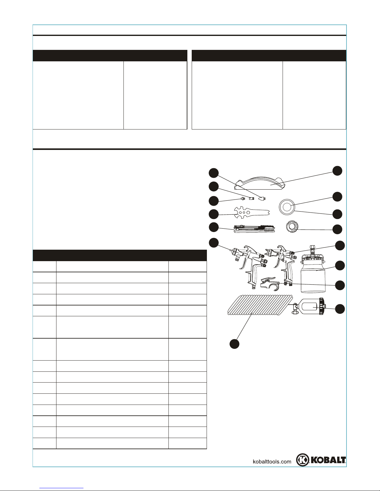
PACKAGE CONTENTS
SPECIFICATIONS
SIPHON
1/4 IN. NPS
45 PSI
3/8 IN.18 NPS(M)
3.9 CFM
1000 CC
COMPONENT
FEED TYPE
INLET CONNECTOR
CUP ADAPTER
AIR CONSUMPTION
PAINT CUP CAPACITY
SPECIFICATIONS
SMALL GRAVITY SPRAY GUN SIPHON FEED SPRAY GUN
DESCRIPTION
Small Gravity Spray Gun
Paint Cup, 250 cc
Siphon Feed Spray Gun
Paint Cup, 1,000 cc
1/4 in. x 25 ft. Recoil Air Hose
Paint Strainer for Siphon
Feed Spray Gun
Cup Lid Gasket for Siphon
Feed Spray Gun
Service Wrench
Spray Gun Cleaning Kit
Air Blow Gun
Blow Gun Nozzle
Safety Nozzle
Rubber Nozzle
Seal Tape
Spray Gun Lube
1
1
1
1
1
10
7
1
1
1
1
1
1
1
1
PART
A
B
C
D
E
F
G
H
I
J
K
L
M
N
O
QUANTITY
A
B
D
C
E
F
G
H
I
J
K
L
M
N
O
Page 4
4
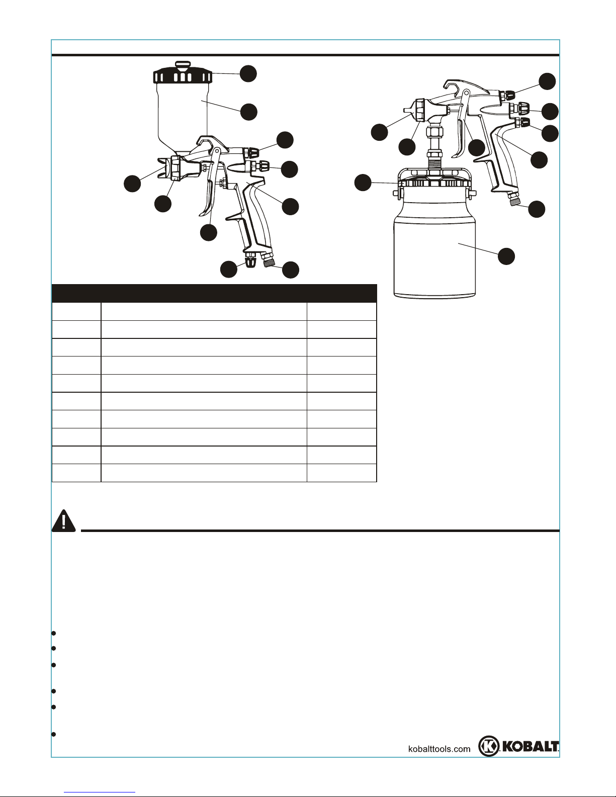
PACKAGE CONTENTS
DESCRIPTION
Spray Gun
Paint Cup
Cup Lid
Air Cap
Air Cap Ring
Spray Pattern Adjustment Knob
Fluid Adjustment Knob
Air Adjustment Knob
Air Inlet
Trigger
QUANTITY
1
1
1
1
1
1
1
1
1
1
PART
A1/A2
B1/B2
C1/C2
D1/D2
E1/E2
F1/F2
G1/G2
H1/H2
I1/I2
J1/J2
A1
B1
C1
D1
E1
F1
H1
I1
G1
J1
A2
B2
C2
D2
E2
F2
H2
I2
J2
SAFETY INFORMATION
Please read and understand this entire manual before attempting to assemble, operate
or install the product. If you have any questions regarding the product, please call
customer service at 1-888-3KOBALT, 8:00 a.m.- 8:00 p.m., EST, Monday-Friday.
FAILURE TO OBSERVE AND FOLLOW THE SAFETY INSTRUCTIONS COULD
RESULT IN INJURY.
WEAR PROPER PROTECTIVE GEAR
Keep loose hair, loose clothing or any hanging jewelry away from all moving parts.
Wear protective safety glasses or face shield to protect eyes.
To reduce the risk of hearing damage ensure you use proper ear protection to safeguard
your hearing.
Dress properly and wear protective clothing when needed.
Whenever possible, it is recommended that electrically non-conductive clothing and
non-skid foot wear be worn when using tools.
Wear a respirator when using tools whenever possible.
G2
Page 5
5
SAFETY INFORMATION
Keep tool out of reach of children and never allow children to handle equipment or tool.
Keep work area clear from clutter and other work hazards.
Do not use this product in unsafe work conditions.
Always be aware of your work area surroundings and the people around the work area
to ensure your safety.
D
item.
o not operate tool if damaged during shipping,handling,or unsafe transportationof the
Using a damaged or unsafe tool can result in serious injury, death, and/or property
damage.
Always check air hoses for weak or worn connections before each use and make certain
that all connections are secure.
Repetitive motions, awkward positions and exposure to vibration can be harmful to
hands and arms.
KEEP CHILDREN AWAY FROM WORK AREA AND TOOL:
WORK ENVIRONMENT HAZARDS
Be aware that extension cords and air hoses may present tripping hazards.
Only use a tool for its intended function.
Always read the label or materials safety data sheet for the materials and or chemicals
that may be used before you use an item to ensure it is safe.
Every tool has a unique function and is designed to operate in a specific way.
ADDITIONAL SAFETY GUIDELINES
Work in a well ventilated area.
Operators must be able to easily handle the bulk weight of the item so that the operator
has full control of the item 100% of the time.
Never operate tool if under the influence of drugs or alcohol.
Never operate tool if you are tired, as operator needs to be in control of tool at all times.
It’s always recommended to have a fire extinguisher and first aid kit near work area.
Keep proper footing at all times and do not overreach, as slipping, tripping, and or falling
Do not abuse hoses or connectors.
can be a major cause of serious injury and or death. Be aware of excess hose left in
working area or work surface.
When using air tools, always carry the tool by the handle. Never carry the tool by the
ohose r yank it to disconnect it from the air or power supply.
Keep hoses away from heat, oil, and sharp edges. Check hoses for weak or worn
connections before each use and make sure that all connections are secure before use.
Do not use pressure exceeding the operation pressure of any of the parts (hoses,
fittings, etc) in the painting system.
If eyes or face come into direct contact with sprayed materials, contact your local doctor
or emergency room for immediate help.
Never aim or spray at yourself or anyone else, which could result is serious injury or death.
Do not spray acids, corrosive materials, toxic chemicals, fertilizers or pesticides. Using
these materials could result in serious injury and or death.
Never spray flammable materials in vicinity of open flame or near ignition sources.
Never store flammable liquids or gases near an air compressor or other compressed
materials under pressure.
Page 6
6
SAFETY INFORMATION
of latex paints. It can be easily and quickly converted from non-bleeder to bleeder,
pressure to siphon feed and internal or external mix air caps. It also features pattern size
control. It can also be converted for use with a separate pressure paint tank.
amount of fluid is adjusted by the fluid control knob, the paint viscosity, and the
air pressure.
to product or workpiece.
This latex spray gun is designed for home, farm and commercial use. It handles all kinds
The pressure for atomization is controlled by the regulator on the air source. The
Failure to install appropriate water/oil removal equipment could result in damage
DANGER
Never spray closer than 25 feet to the air compressor. If possible, place compressor
.moor etarapes a ni
Certain materials that can be used with this device if coming in direct contact with skin
may cause skin irritation.
Use a face mask/respriator and protective clothing when spraying. Always spray in a
well ventilated area to prevent health and fire hazards. Refer to material saftey data
sheets (MSDS) of spray materials for details.
Read the label or materials safety data sheet for the materials you intend to use to find
out which materials may cause skin irritation.
Always disconnect tool from air supply before performing any maintenance.
Never use a tool which is leaking air, has missing or damaged parts, or requires repair.
Only use parts and accessories recommended by the manufacturer.
WARNING
SOME DUST CREATED BY PAINT SPRAYING, POWER SANDING, SAWING,
GRINDING, DRILLING, AND OTHER RELATED ACTIVITIES KNOWN TO THE
STATE OF CALIFORNIA TO CAUSE CANCER, BIRTH DEFECTS, AND OTHER
REPRODUCTIVE HARM. A LISTING OF CHEMICALS CAN BE OBTAINED FROM
www.oehha.ca.gov UNDER PROPOSITION 65. SOME EXAMPLES OF THESE
CHEMICALS ARE:
YOUR RISK FROM THESE EXPOSURES VARIES, DEPENDING ON HOW OFTEN
YOU DO THIS TYPE OF WORK. TO REDUCE YOUR EXPOSURE TO THESE
CHEMICALS WORK IN A WELL VENTILATED AREA, AND WORK WITH APPROVED
SAFTEY EQUIPMENT, SUCH AS A RESPRIATOR OR DUST MASKS WHICH ARE
SPECIALLY DESIGNED TO FILTER MICROSOPIC PARTICLES.
LEAD FROM LEAD BASED PAINTS
CRYSTALLINE SILICA FROM BRICKS, CEMENT AND OTHER MASONRY
PRODUCTS
ARSENIC AND CHROMIUM FROM CHEMICALLY TREATED LUMBER
NOTE
Page 7

ASSEMBLY INSTRUCTIONS
7
1. Take out spray gun (A1/A2) and put on paint cup
(B1/B2) with hand. Make sure that the paint cup
(B1/B2) is installed with spray gun (A1/A2) tightly
and correctly. (See Figure 2)
2. Connect recoil air hose or air supply hose with
the air inlet (I1/12) of spray gun (A1/A2). Use seal
tape (N) for airtight connection. Do not overtighten.
(See Figure 3).
NOTE The working pressure refers to the air line
pressure when the spray gun trigge dellup si)2J/1J( r
fully under working conditions.
3. Set the rated working pressure (i.e. 40 PSI for
small gravity spray gun and 45 PSI for siphon
feed spray gun) for best performance.
2
A2
B1
A1
B2
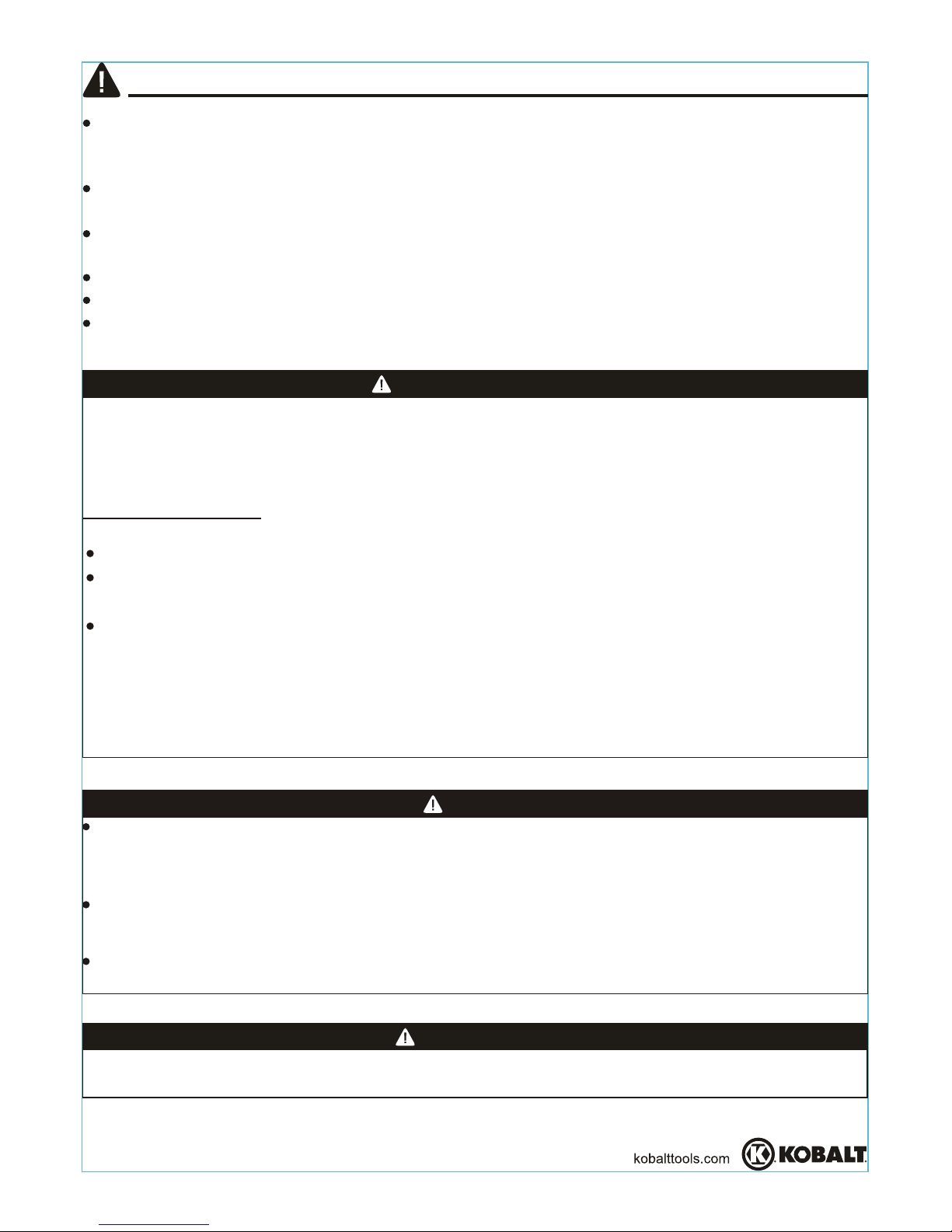
Note:The life of this product and the efficiency of its
operation depends upon the knowledge of its
construction, usage and maintenance (See Figure 1;
Not all accessories shown are included, but are
recommended for best performance).
Oil and
Water
Extractor
Atomization
Pressure Gauge
1
PREPARATION
Before beginning the assembly of the product, make sure all parts are present.
Compare parts with package contents list. If any part is missing or damaged, do not
attempt to assemble the product.
Estimated Assembly Time: 5-10 minutes
Tools Required for Assembly: Adjustable wrench (not included)
3
I1
I2
Page 8
OPERATING INSTRUCTIONS
8
NOTE During normal use, the air ca si )2D/1D( p
adjusted to be horizontal. This provides a vertical
fan-shaped pattern which gives maximum and
even material coverage as the gun is moved back
and forth parallel to the surface being finished.
Air Cap
Air Cap Ring
Horizontal Fan
Vertical Fan
1
4
Load paint
Load paint
ASSEMBLY INSTRUCTIONS
4. Pour paint into the paint cup. Hold or adjust paint cup
so that paint can be easily added and controlled
once paint is inside cup. Secure paint cap lid
turning clockwise by hand (See Figure 4; Not all
accessories shown are included).
NOTE
Before using desired paint in the spray gun, spray a compatible thinner or solvent
through the gun to remove any contaminants and residues.
Thin paints properly in accordance with the paint manufacturer's instructions
before spraying.
Fill the paint cup (B1/B2) about 3/4 full and start the air compressor.
Set up a piece of cardboard or other scrap material to use as a target and adjust
for best spray pattern.
Test the consistency of the paint by making a few strokes on a cardboard target. If
paint still appears
too thick, add a small amount of thinner. Do not exceed paint
manufacturer's thinning recommendations.
WARNING
The paint sprayer will not properly spray unless
the fan direction is either horizontal or vertical.
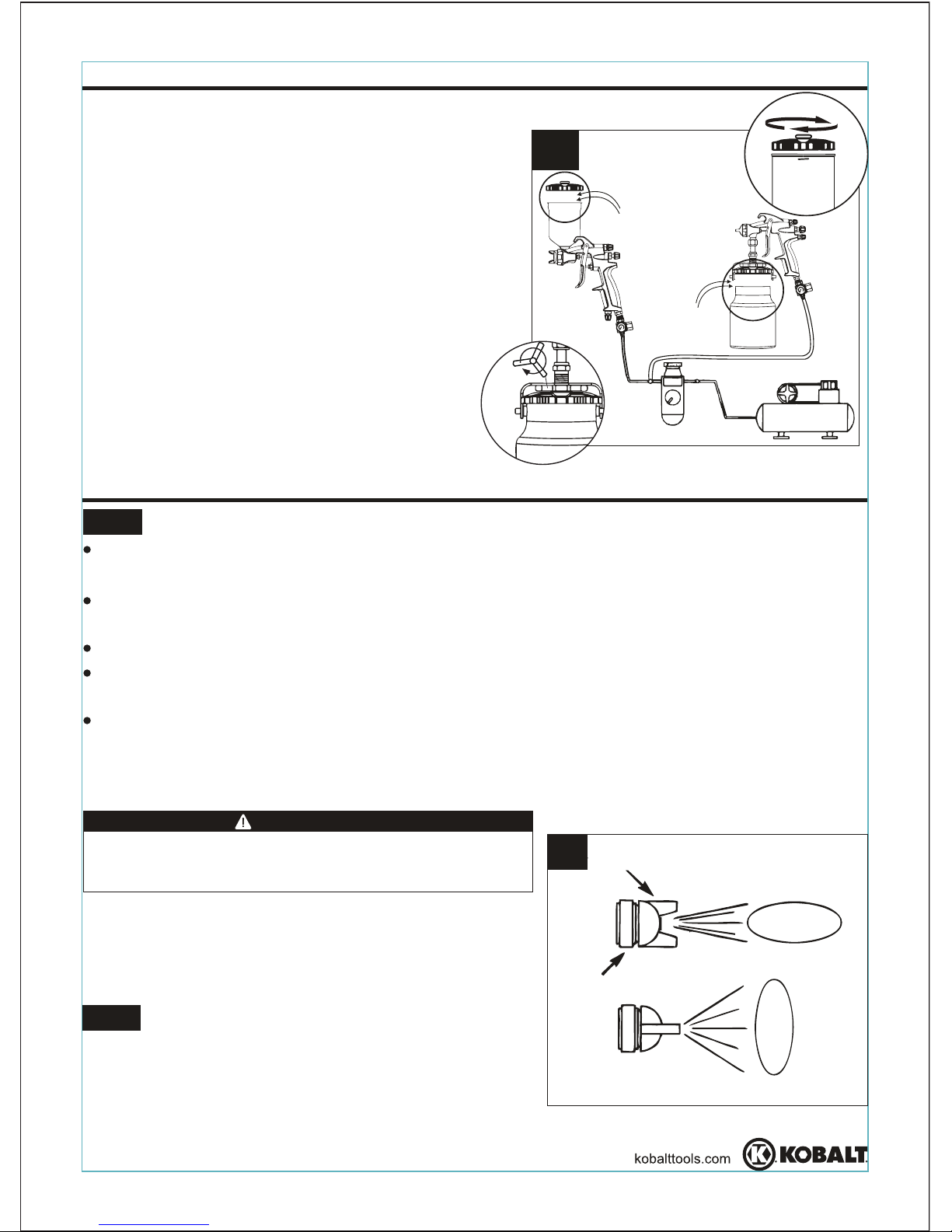
1. Adjust the direction of fan to be either horizontal
or vertical as required by loosening the air cap
ring (D1/D2) 90 degrees. Hand tighten the air
ring (E1/E2) after adjustment (See Figure 1).
Clockwise
A
A
B
B
cap
Clockwise
Page 9
OPERATING INSTRUCTIONS
9
Paint too fine
Correct
Paint too coarse
Pattern Consistency (Atomization)
4
2
3
2. Set pattern size for desired shape. For full
pattern, open spray pattern adjustment knob
spray pattern adjustment kno )2F/1F(b
(See Figure 2)
3. Turn the fluid adjustment knob (G1/G2) fully
clockwise until closed. (See Figure 3)
F1
F2
4. With
the spray gun 6 in. to 9 in.
awa
yfrom
workpiece,
spray a short burst while
turning
the
fluid knob
counterclockwise. Observe
the spray
pattern
on
the
workpiece
and adjust the fluid
control
knob (G1/G2)(see Figure 3) until
desired
pattern/atomization
is
obtained.
If the spray is too
the air
pressure
or openthe fluid control knob(G1/G2) to
spray more paint. If the spray
reduce
the
amount
of paint with the
fluid
control
knob (G1/G2)or thin the paint more
fine (caused by too much air), reduce
is too coarse or
spitting blobs,
(See Figure 4).
NOTE The fluid control knob (G1/G2) can be
either clockwise or counterclockwise to
finely consistency. Before
spraying on workpiece, practice a few minutes on a
cardboard target to ensure that the pattern size and
consistency are set correctly.
adjust the pattern
G1
G2
(F1/F2) counterclockwise. For a round pattern,
turn
clockwise.
adjusted
Page 10
OPERATING INSTRUCTIONS
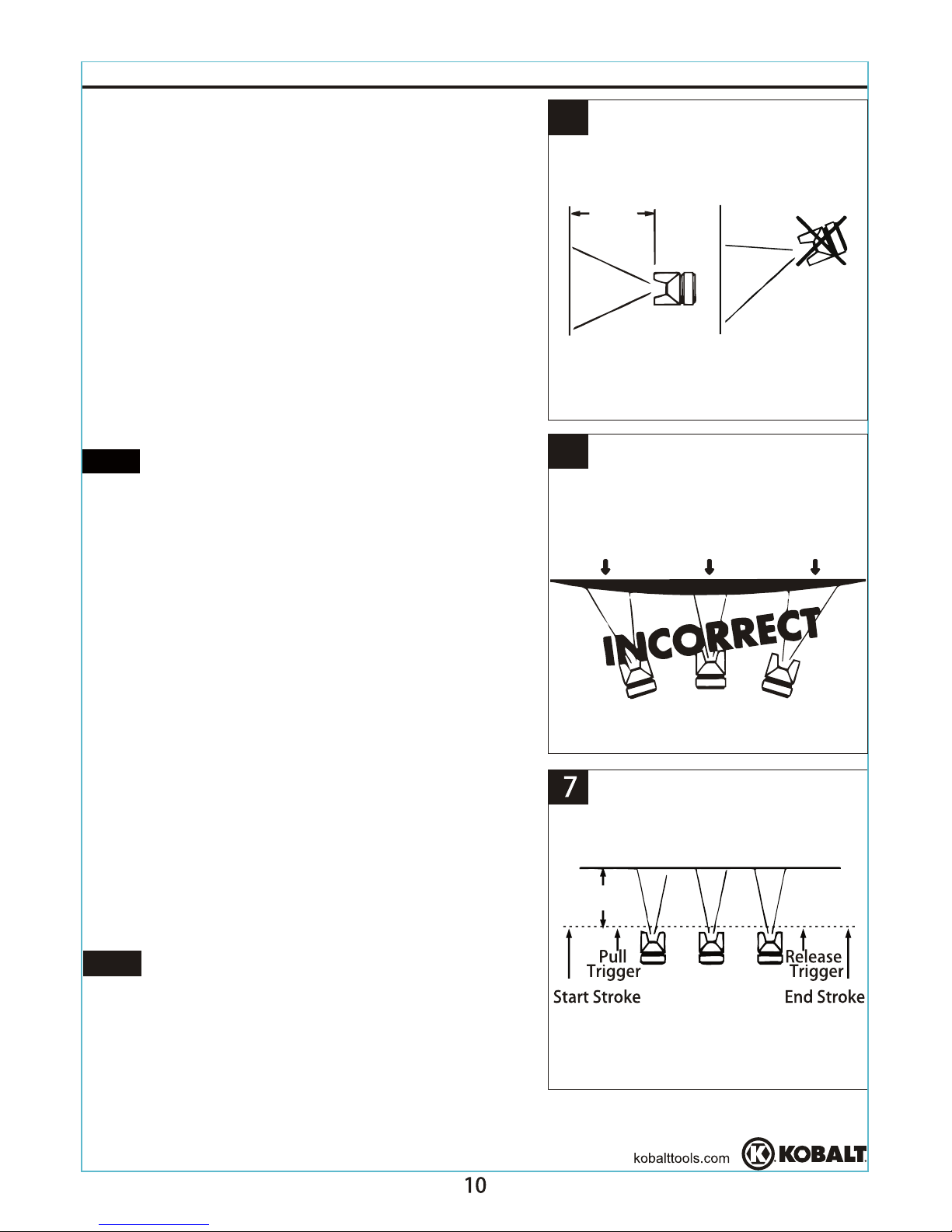
6. Trigger the gun properly. Start the gun moving at
the beginning of the stroke before squeezing the
trigger (J1/J2) and release the trigger (J1/J2)
stopping gun movement at the end of
This procedure will feather/blend each .ekorts
ekorts
with the next without showing overlap or
unevenness. (See Figure 7)
NOTE The amount of paint being applied can be
varied by the speed of stroke, distance from
workpiece and adjustment of fluid adjustment knob
(G1/G2). If speed of stroke is too slow, paint will
be wet on workpiece and may run. If speed of
fast, paint will be dry and uneven on
6 - 9 in.
6 - 9 in.
5
Thin coat Heavy coat Thin coat
6
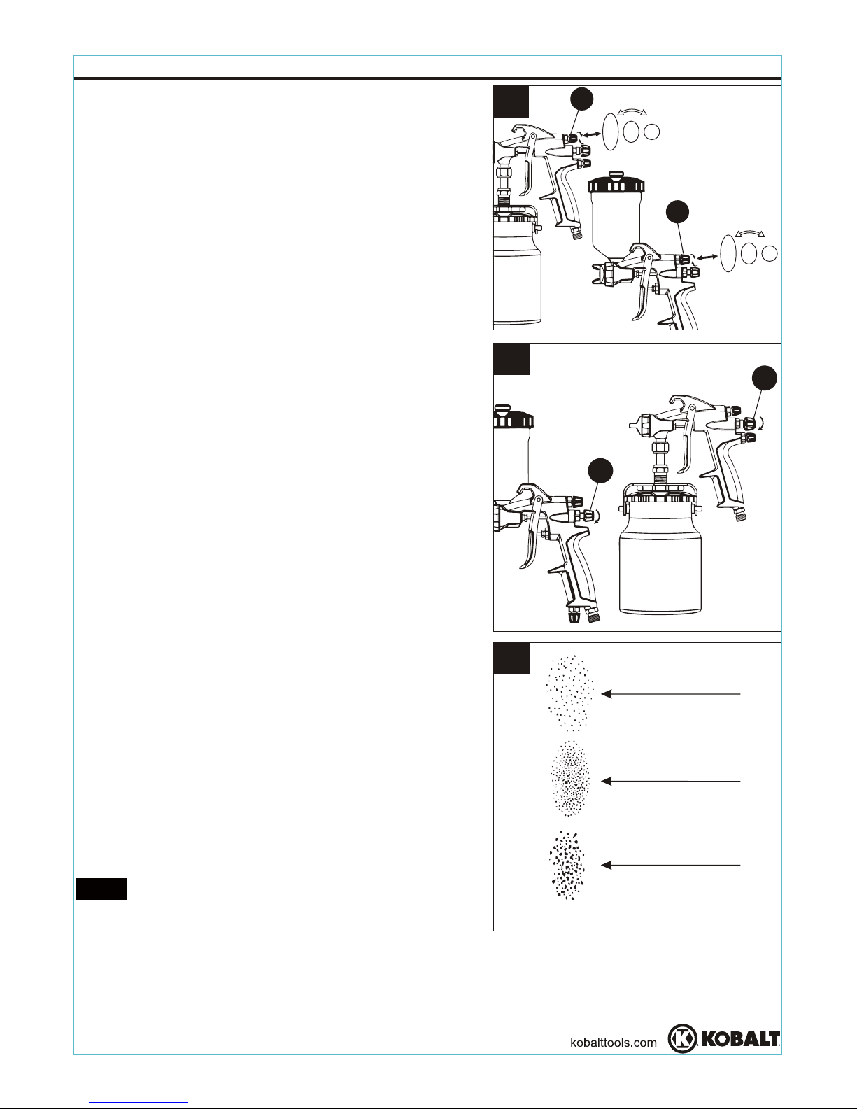
5. Keep the gun at a 90° angle to the surface
(see Figure 5) while spraying.
NOTE Always keep the gun in motion while
spraying. Stopping gun movement in mid-stroke
will causeabuild-up of paint and will result in runs.
Do not fan the gun from side to side while painting.
This will cause a build-up of paint in the center of
stroke and an insufficient coating at each end
(See Figure 6).
the
before
is toostroke
workpiece.
Page 11
CARE AND MAINTENANCE
OPERATING INSTRUCTIONS
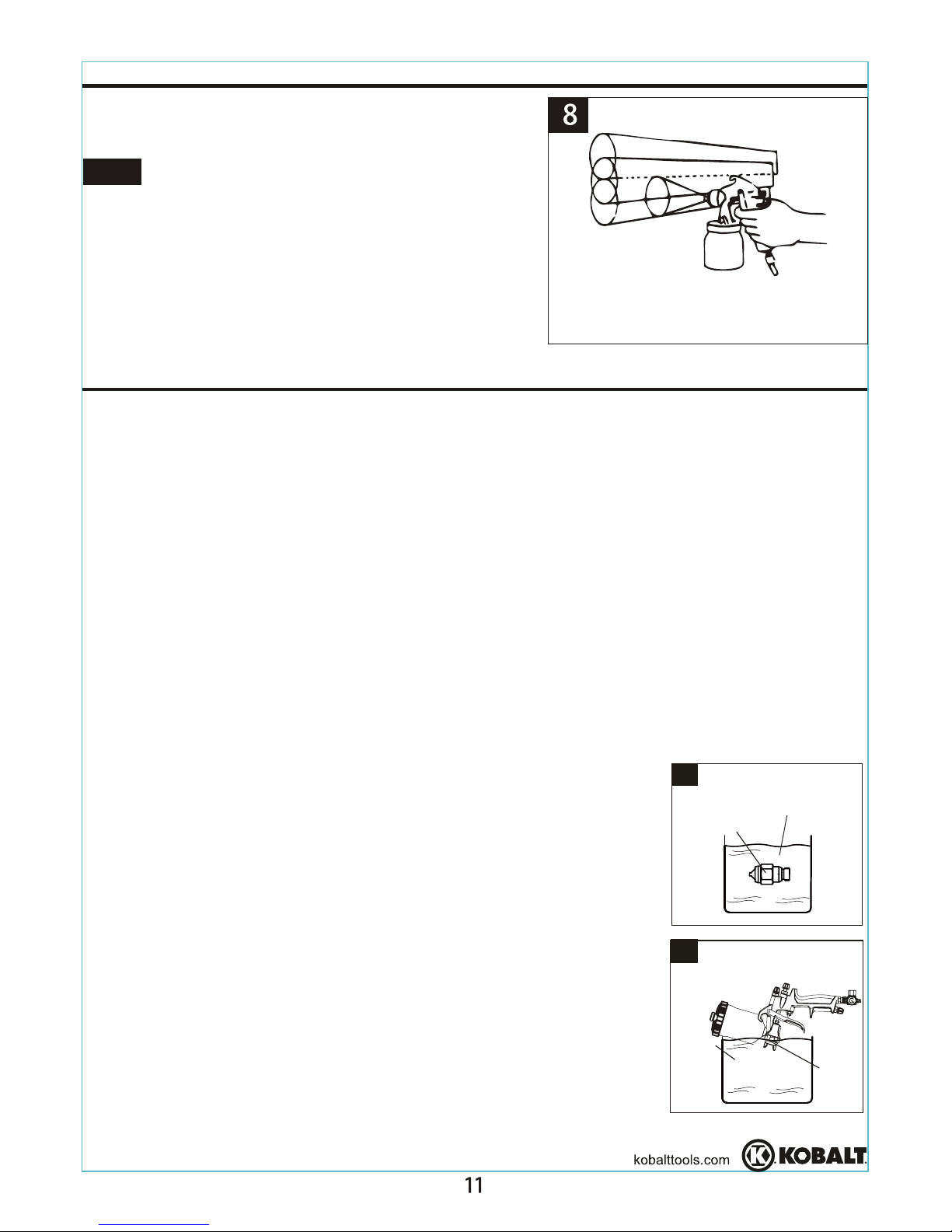
7. Overlap strokes just enough to obtain an even
and fine coat. (See Figure 8)
8. Use a piece of cardboard as a shield to catch
overspray at the edges of workpiece and protect
other surfaces. Use masking tape (not included)
to cover other areas if needed.
NOTE Two thin coats of paint will yield better
spraying results and have less chance of runs than
one heavy layer.
To properly maintain and keep your sprayer working at its optimal performance,
it is recommended that the spray gun nozzle be cleaned and cleared of any clogs or
debris buildup
using paint thinner or lacquer thinner. DO NOT USE ANY ACID
BASED SOLVENTS, AS ACID BASED SOLVENTS CAN DAMAGE THE SPRAYER.
Please consult with your local retailer in choosing the right solvent materials.
1. Pour enough solvent material(s) into container so that nozzle will be completely
submerged in solvent material.
BEFORE PERFORMING ANY CLEANING OR MAINTENANCE REMOVE SPRAY
GUN FROM AIR SUPPLY AND KEEP AWAY FROM ANY IGNITION SOURCES.
COMPLETELY EMPTY CUP WHEN PERFORMING AND MAINTENCE OR
CLEANING.
9
Nozzle
Solvent material
Solvent
material
NOTE: There are two methods for properly submerging spray gun nozzle into
cleaning solvent material(s).
Method 2: Keeping the spray gun nozzle attached to the
NOTE: Make sure that you never submerge any part of the
spray gun housing into solvent material(s), as air passages
would become clogged with dirty solvent. This would
cause
the gaskets inside the gun housing
to dry out, causing faster
Method 1: Remove the spray gun nozzle completely from
spray gun and place into a container that will not cause
solvent deterioration when solvent material(s) are added
10
Nozzle
(See Fig. 9).
spray gun housing. Empty canister and submerge the front
end of the spray gun only (See Fig. 10). Make sure that only
the spray gun nozzle is submerged in solvent material(s). (If
using method 2, make sure a suitable container is used which
can not easily tip over. If the container used does tip over,
you will spill
solvent material(s), causing a potential safety
hazard.)
wear and tear on the item.
Page 12
Soak nozzle in solvent to loosen
the clog, then blow air through until
clean. To clean orifices use a
broom straw or toothpick. Never
try to detach dried material with
sharp tool.
One side of nozzle is
clogged.
T
ROUBLESHOOTING
POSSIBLE CAUSE SOLUTION
a) Atomization air pressure
is set too high.
b) Trying to spray a thin
material in too wide of a
pattern.
a) Reduce air pressure.
b) Increase material control by
turning fluid adjustment knob
to left, while reducing spray
width by turning spray pattern
adjustment knob to right.
a) Loosen air nozzle.
b) Material around outside
of air nozzle has dried.
a) Trigger air nozzle.
b) Take off air nozzle and wipe
off fluid tip using a rag
moistened with thinner.
PROBLEM
Right or left heavy
spray pattern
Top or bottom heavy
spray pattern
Split spray pattern
12
2. Let nozzle sit in solvent materia
l(s) for 3-5 minutes allowing solvent material(s) to
break up any build up of dirt and or debris on spray nozzle.
3. Remove
nozzle
from solvent material
(s)
and closely inspect the spray gun
nozzle
to ensure any
dirt or debris build up has been cleared.
NOTE: Depending on the paint and solvent material(s) used, steps 1-4 may need to
be repeated multiple times.
4. If debris or build up is still present, use a non-wire soft bristle brush and brush area
of nozzle that still contains dirt or debris and repeat steps 1-4.
. Once the spray gun nozzle has been completely cleared of any dirt or debris and is
clean, wipe the nozzle clean with a clean cloth or rag.
. Once nozzle has been properly cleaned, reconnect the nozzle to the spray gun and
reconnect the spray gun to the air supply. Test the sprayer ensuring that it is
working properly.
Storing:
1. When not using the spray gun turn the fluid adjustment knob counterclockwise (to
open) which will reduce the spring tension on the needle fluid tip.
2. Spray gun must be well cleaned and lightly lubricated.
3. Store spray gun in a dry and safe place out of reach of children.
CARE AND MAINTENANCE
Page 13
13
TROUBLESHOOTING
POSSIBLE CAUSE SOLUTIONPROBLEM
a) Packing nut loose.
b) Packing worn or dry.
a) Tighten, but not so tight as to
grip needle.
b) Replace packing or lubricate.
Fluid leakage
from packing
nut.
a) Dry packing.
b) Sluggish needle.
c) Tight packing nut.
d) Worn fluid nozzle
or needle.
a) Lubricate.
b) Lubricate.
c) Adjust.
d) For pressure feed, replace
with new fluid nozzle and
needle.
Dripping from
fluid tip.
a) Gun held too far from
surface.
b) Atomization pressure
set too high.
a) Move gun closer to surface.
b) Adjust atomization pressure.
Thin, sandy
coarse finish.
Gun held too close to
surface.
Move gun further from surface.
orange peel.
Thick, dimpled
finish resembling
a) No air pressure at gun.
b) Fluid pressure too low
with internal mix cap
and pressure tank.
c) Fluid control screw not
open enough.
d) Fluid too heavy for
suction feed.
a) Check air supply and air lines.
b) Increase fluid pressure at tank.
c) Open fluid control screw.
d) Thin material or change to
pressure feed.
Will not spray.
a) Gun improperly adjusted.
b) Dirty air cap.
c) Fluid tip obstructed.
d) Sluggish needle.
Fan adjustment screw not
seating properly.
Clean or replace.
a) Re-adjust gun. Follow
instructions carefully.
b) Clean air cap.
c) Clean.
d) Lubricate.
Unable to get
round spray.
Improper spray
pattern.
Intermittent
spray
a) Packing around needle
valve is dried out.
b) Fluid nozzle loosely
installed or dirt between
nozzle and body.
c) Needle sealing
damaged.
a) Back up knurled nut, put a few
drops of machine oil on
packing, retighten nut.
b) Take off fluid nozzle, clean
rear of nozzle and seat in gun
body. Replace nozzle and
tighten to body.
c) Replace seal.
Page 14
T, Monday-Friday.
Page 15
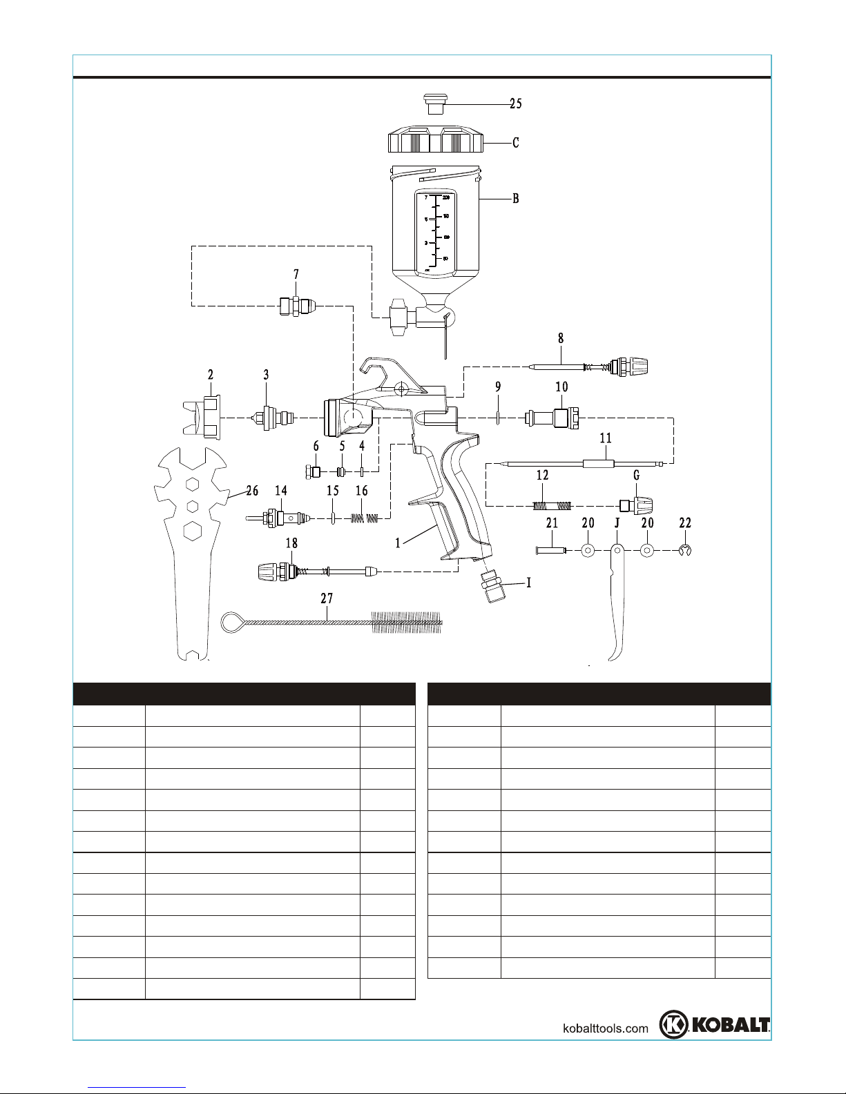
EXPLODED VIEWS
15
15
16
I1
18
J1
20
21
22
B1
C1
25
26
27
1
2
3
4
5
6
7
8
9
10
11
12
G1
14
1
1
1
1
1
1
1
1
1
1
1
1
1
1
1
1
1
1
1
2
1
1
1
1
1
1
1
Part No.
Description Qty.
Part No.
Description Qty.
Gun body
Air cap w/ring
Fluid nozzle
Washer
Seal ring
Leadscrew
Fluid nipple
Spread adj. valve set
O-ring 7x1.5
Fluid adj. guide set
Paint needle
Needle spring
Fluid adj. knob
Air valve assembly
Spring
O-ring 6x1.5
Air inlet
Air adj. valve assembly
Trigger
Gasket
Trigger pin
E-ring
Paint cup
Cup lid
Non-drip control device
Wrench
Brush
LR
PO
Page 16
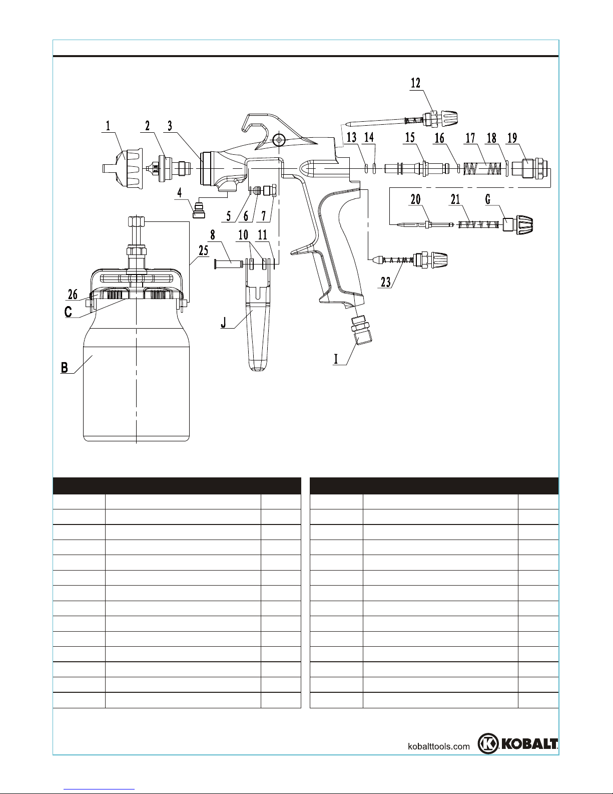
EXPLODED VIEWS
Printed in China
16
15
16
17
18
19
20
21
G2
23
25
26
I2
C2
B2
1
2
3
4
5
6
7
8
J2
10
11
12
13
14
1
1
1
1
1
1
1
1
1
2
1
1
1
1
1
1
1
1
1
1
1
1
1
1
1
1
1
1
Part No.
Description Qty.
Part No.
Description Qty.
Air cap w/ring
Fluid nozzle
Gun body
Fluid connection
Washer
Seal ring
Leadscrew
Trigger pin
Trigger
Washer
E-ring
O-ring 6.3x2
O-ring 6x2.65
Air valve
O-ring 5x1.8
O-ring 9x1.8
Air valve spring
Fluid adj. guide set
Paint needle
Needle spring
Fluid adj. knob
Air valve assembly
Air inlet
Complete lid assembly
Gasket
Cup lid
Paint cup
Spray pattern adj. assembly
KOBALT and the K Design are registered
trademarks of LF, LLC. All Rights Reserved.
®®
Page 17

JOIGNEZ VOTRE REÇU ICI
17
ARTICLE #0105568
45 PIÈCES ENSEMBLE
DE PISTOLET DE
PULVÉRISATION
MODÈLE #SGY-AIR160TZ
KOBALT et le motif de K sont des marques de
commerce déposées de LF, LLC. Tous droits réservés.
®®
Numéro de série Date d'achat
Des questions, des problèmes, des pièces manquantes? Avant de
retourner l'article au détaillant, communiquez avec notre service à la
clientèle au 1 888 3KOBALT, entre 8 h et 20 h (HNE), du lundi au vendredi.
Page 18

TABLE DES MATIÈRES
18
Caractéristiques du produit ...................................................................................19
Consignes de sécurité ..........................................................................................
20........................................................................................Contenu de l'emballage
Préparation .......................................................................................................... 24
Instructions pour l'assemblage..............................................................................24
Mode d'emploi...................................................................................................... 26
Entretien................................................................................................................29
Dépannage ...........................................................................................................
Garantie ...............................................................................................................32
Vues éclatées ......................................................................................................33
3.3
CFM PSI
Tool Requirements
Exigences relatives aux outils
Requisitos de herramientas
@
40
3.9
CFM PSI
@
45
21
30
Tool Requirements
Exigences relatives aux outils
Requisitos de herramientas
IMPORTANT: Cet outil nécessite un débit d'air d'au moins 3,3 pi par minute à une pression de
40 lb/psi . Vérifiez les spécifications de votre compresseur d'air afin de vous assurer qu'il satisfait aux
exigencies minimales (pi /min et lb/psi ). L'utilisation d'un tuyau à air peut entraîner une chute de
pression de jusqu'à 15 lb/psi. peut donc s'avérer nécessaire d'augmenter la pression afin de maintenir
un niveau adéquat.
3
2
32
PETIT PISTOLET DE PULVÉRISATION À GRAVITATION
PISTOLET DE PULVÉRISATION À SIPHON
IMPORTANT: Cet outil nécessite un débit d'air d'au moins 3,9 pi par minute à une pression de
45 lb/psi . Vérifiez les spécifications de votre compresseur d'air
afin de vous assurer qu'il satisfait
aux exigencies minimales (pi /min et lb/psi ). L'utilisation d'un tuyau à air peut entraîner une chute
de pression de jusqu'à 15 lb/psi.
Il peut donc s'avérer nécessaire d'augmenter la pression afin de
maintenir un niveau adéquat.
3
3
2
2
Page 19

19
NS
CARACTÉRISTIQUES DU PRODUIT
COMPOSANTE
TYPE D'ALIMENTATION
RACCORD D'ENTRÉE
PRESSION DE SERVICE
ADAPTATEUR DU RÉSERVOIR
CONSOMMATION D'AIR
CAPACITÉ DU RÉSERVOIR À PEINTURE
PETIT PISTOLET DE PULVÉRISATION À GRAVITATION
CARACTÉRISTIQUES
GRAVITATION
1/4 PO NPS
2
40 lb/po
1/4 PO. 19 NPS(M)
3
3,3 pi /min
3
250 cm
PRESSION DE SERVICE
PISTOLET DE PULVÉRISATION À SIPHON
COMPOSANTE
TYPE D'ALIMENTATION
RACCORD D'ENTRÉE
ADAPTATEUR DU RÉSERVOIR
CONSOMMATION D'AIR
CAPACITÉ DU RÉSERVOIR À PEINTURE
CARACTÉRISTIQUES
SIPHON
1/4 PO NPS
2
45 lb/po
3/8 PO. 18 NPS(M)
3
3,9 pi /min
3
1000 cm
Page 20

20
NS
A
B
D
C
E
F
G
H
I
J
K
L
M
N
O
CONTENU DE L'EMBALLAGE
DESCRIPTION
Petit pistolet de pulvérisation
à gravitation
Réservoir à peinture en
plastique d'une capacité de
3
250 cm
Pistolet de pulvérisation à
siphon
Réservoir à peinture en
aluminium d'une capacité de
3
1000 cm
Tuyau à air rétractable de
1/4 po et 7,62 m
Filtre à peinture pour pistolet
de pulvérisation à siphon
Joint de couvercle de
réservoir pour pistolet de
pulvérisation à siphon
Clé
Trousse pour le nettoyage du
pistolet de pulvérisation
Soufflette à air
Buse de soufflette à air
Buse de sécurité
Buse de caoutchouc
Ruban à joints
Lubrifiant pour pistolet de
pulvérisation
1
1
1
1
1
10
7
1
1
1
1
1
1
1
1
A
B
C
D
E
F
G
H
I
J
K
L
M
N
O
QUANTITÉ
PIÈCE
Page 21

21
CONTENU DE L'EMBALLAGE
DESCRIPTION
Pistolet de pulvérisation
Réservoir à peinture
Couvercle de réservoir
Obturateur d'air
Anneau de l'obturateur d'air
Bouton de réglage de l'étendue du jet
Bouton de réglage du fluide
Bouton de réglage de l'air
Entrée d'air
Gâchette
QUANTITÉ
1
1
1
1
1
1
1
1
1
1
PIÈCE
A1/A2
B1/B2
C1/C2
D1/D2
E1/E2
F1/F2
G1/G2
H1/H2
I1/I2
J1/J2
A1
B1
C1
D1
E1
F1
H1
I1
G1
J1
CONSIGNES DE SÉCURITÉ
LE NON-RESPECT DES CONSIGNES DE SÉCURITÉ PEUT ENTRAÎNER DE
GRAVES BLESSURES.
PORTEZ UNE TENUE DE PROTECTION ADÉQUATE
Gardez les cheveux, les vêtements amples et tout bijou pendant loin des pièces mobiles.
Portez des lunettes de sécurité ou un écran facial afin de protéger vos yeux.
Afin de réduire les risques de dommages auditifs, assurez-vous de porter des protecteurs
auditifs pour protéger votre ouïe.
Habillez-vous convenablement et portez des vêtements de protection lorsque nécessaire.
Dans la mesure du possible, il est recommandé de porter des vêtements non
conducteurs et des chaussures antidérapantes lorsque vous utilisez des outils.
Dans la mesure du possible, portez un masque anti-vapeurs lorsque vous utilisez des
outils.
A2
B2
C2
D2
E2
F2
H2
I2
J2
G2
Assurez-vous de lire et de comprendre l'intégralité de ce manuel avant de tenter
d'assembler, d'utiliser ou d'installer le produit. Si vous avez des questions, veuillez
communiquer avec notre service à la clientèle au 1 888 3KOBALT, entre 8 h et 20 h
(HNE), du lundi au vendredi.
Page 22

22
CONSIGNES DE SÉCURITÉ
Gardez l’outil hors de la portée des enfants et ne laissez jamais les enfants manipuler
l’équipement ou l’outil.
Gardez l’aire de travail dépourvue de débris et de tout danger lié au travail.
N’utilisez pas cet article dans des conditions de travail dangereuses.
Pour des raisons de sécurité, soyez toujours attentif à votre environnement de travail
et aux gens qui se trouvent à proximité.
N’utilisez pas l’outil s’il a été endommagé lors de l’envoi, de la manipulation ou du
transport dans des conditions dangereuses.
L’utilisation d’un outil endommagé ou dangereux peut entraîner des blessures graves,
la mort ou des dommages matériels.
Vérifiez toujours l’état des tuyaux à air avant chaque utilisation et assurez-vous
qu’ils sont bien solides.
Les mouvements répétitifs, les positions inconfortables et l’exposition aux vibrations
peuvent présenter un danger pour les mains et les bras.
GARDEZ LES ENFANTS À DISTANCE DE L’AIRE DE TRAVAIL ET DE L’OUTIL :
DANGERS LIÉS AUX ENVIRONNEMENTS DE TRAVAIL
N’oubliez pas que les rallonges et les tuyaux à air peuvent vous faire trébucher.
Utilisez uniquement un outil pour l’usage auquel il est destiné.
Afin de savoir quels matériaux ou produits chimiques peuvent utiliser être utilisé de
façon sécuritaire avec un article, lisez toujours son étiquette ou sa fiche signalétique.
Chaque outil a une fonction unique et est conçu pour être utilisé de manière précise.
CONSIGNES DE SÉCURITÉ SUPPLÉMENTAIRES
Travaillez dans un endroit bien ventilé.
Les utilisateurs doivent être en mesure de supporter facilement le poids de l’article
afin d’en avoir le plein contrôle en tout temps.
N’utilisez jamais l’outil lorsque vous êtes sous l’effet de drogues ou d’alcool.
N’utilisez jamais l’outil si vous êtes fatigué puisque vous devez en garder le contrôle
en tout temps.
Il est toujours recommandé d’avoir un extincteur d’incendie et une trousse de
premiers soins à proximité de l’aire de travail.
Gardez une posture sécuritaire en tout temps, ne vous étirez pas pour étendre votre
portée; vous risqueriez de glisser, de trébucher ou de tomber et de subir des
blessures graves ou mortelles. Faites attention à l’excédent de tuyau laissé dans
l’aire de travail ou sur la surface.
Ne faites pas un usage abusif des tuyaux ou des connecteurs.
Transportez toujours l’outil en le tenant par la poignée; ne le transportez jamais en le
tenant par le tuyau et ne tirez jamais pour le débrancher de l’alimentation en air ou en
électricité.
Tenez les tuyaux éloignés des sources de chaleur, de l’huile et des objets coupants.
Vérifiez l’état des tuyaux avant chaque utilisation et assurez-vous qu’ils sont bien
solides.
N’excédez pas la pression de fonctionnement des pièces (p. ex., tuyaux, raccords,
etc.) de l’outil de peinture.
Si les yeux ou le visage entrent en contact direct avec des matériaux vaporisés,
communiquez avec votre médecin ou avec une salle d’urgence pour obtenir de
l’aide immédiate.
Page 23

23
CONSIGNES DE SÉCURITÉ
Ne pointez jamais le pistolet vers vous-même ou une autre personne, car vous pourriez
causer de graves blessures ou la mort.
AVERTISSEMENT
Ne pulvérisez pas d’acide, de matières corrosives, de produits chimiques toxiques, de
fertilisants ou de pesticides. L’utilisation de ces matières peut causer de graves
blessures, voire entraîner la mort.
Ne pulvérisez jamais de matières inflammables à proximité d’une flamme nue ou d’une
source d’inflammation.
Ne rangez jamais de liquides inflammables ou de gaz à proximité d’un compresseur
d’air ni d’autres matériaux comprimés.
Portez un masque facial ou un masque anti-vapeurs ainsi que des vêtements de
protection pendant la pulvérisation.
Utilisez toujours le pistolet de pulvérisation dans un endroit bien aéré afin de prévenir
les risques d’incendie et les dangers pour la santé. Pour de plus amples amples
renseignements, consultez la fiche signalétique (FS) des matériaux à pulvériser.
Certains matériaux pouvant être utilisés avec cet appareil peuvent causer des
irritations cutanées s’ils entrent en contact direct avec la peau.
Lisez l’étiquette ou la fiche signalétique pour savoir si les matériaux que vous
désirez utiliser peuvent causer des irritations cutanées.
Coupez toujours l’alimentation en air avant d’effectuer tout entretien.
N’utilisez jamais un outil qui présente une fuite d’air, auquel il manque des pièces,
dont des pièces sont endommagées ou qui nécessite une réparation.
N’utilisez que des pièces et accessoires recommandés par le fabricant.
LA POUSSIÈRE CRÉÉE PENDANT LE PONÇAGE, LE SCIAGE, LE POLISSAGE,
LE PERÇAGE ET D'AUTRES ACTIVITÉS PEUT CONTENIR DES PRODUITS
CHIMIQUES RECONNUS PAR L'ÉTAT DE LA CALIFORNIE COMME ÉTANT LA
CAUSE DE CANCERS, D'ANOMALIES CONGÉNITALES ET D'AUTRES
PROBLÈMES LIÉS AUX FONCTIONS REPRODUCTRICES. VOUS POUVEZ
OBTENIR LA LISTE DES PRODUITS CHIMIQUES AU www.oehha.ca.gov,
CONFORMÉMENT À LA PROPOSITION 65. VOICI QUELQUES-UNS DE CES
PRODUITS CHIMIQUES :
DU PLOMB PROVENANT DE PEINTURES À BASE DE PLOMB;
DE LA SILICE CRISTALLINE PROVENANT DE LA BRIQUE, DU CIMENT OU
D'AUTRES MATÉRIAUX DE MAÇONNERIE;
DE L'ARSENIC ET DU CHROME PROVENANT DU BOIS D'OEUVRE TRAITÉ AVEC
UN PRODUIT CHIMIQUE.
LES RISQUES LIÉS À L’EXPOSITION À CES PRODUITS VARIENT SELON LE
NOMBRE DE FOIS OÙ VOUS PRATIQUEZ CES ACTIVITÉS. AFIN DE LIMITER
VOTRE EXPOSITION À CES PRODUITS CHIMIQUES, TRAVAILLEZ DANS UN
ENDROIT BIEN VENTILÉ ET UTILISEZ DE L’ÉQUIPEMENT DE SÉCURITÉ
APPROUVÉ, TEL QU’UN APPAREIL RESPIRATOIRE OU UN MASQUE
ANTIPOUSSIÈRE CONÇUS SPÉCIALEMENT POUR FILTRER LES PARTICULES
MICROSCOPIQUES.
Page 24

INSTRUCTIONS POUR L'ASSEMBLAGE
24
REMARQUE: La durée de vie de ce produit et
l’efficacité de son fonctionnement dépendent des
connaissances de l’utilisateur relativement à sa
conception, son utilisation et son entretien (consultez
la figure 1; Certains des accessoires illustrés ne sont
pas inclus, mais leur installation est recommandée afin
d’obtenir un rendement optimal).
Pulvérisation
Manomètre
1
PRÉPARATION
CONSIGNES DE SÉCURITÉ
Avant de commencer l'assemblage du produit, assurez-vous d'avoir toutes les pièces.
Comparez les pièces dans l'emballage avec la liste ci-dessus. S'il y a des pièces
manquantes ou endommagées, ne tentez pas d'assembler le produit. Communiquez
avec le service à la clientèle pour obtenir des pièces de rechange.
Ce pistolet de pulvérisation pour latex est conçu et fabriqué pour un usage résidentiel,
agricole et commercial. Il permet l’application de toute sorte de peinture au latex. Il est
facile et rapide de convertir le modèle : purgeur ou non, avec alimentation à pression
ou à siphon, et avec obturateur d’air à mélange interne ou externe. Ce pistolet permet
également de régler la largeur du jet. Il peut aussi être converti pour être utilisé avec
un réservoir de peinture sous pression distinct.
La pression de pulvérisation est déterminée par le régulateur de la source
d’alimentation en air. Le bouton de réglage du fluide, la viscosité de la peinture et la
pression d’air permettent de régler la quantité de fluide pulvérisée.
Si vous n’installez pas l’équipement approprié servant à l’élimination de l’huile et de
l’eau, vous pourriez endommager le produit ou la pièce.
DANGER
Ne pulvérisez jamais de peinture à moins de 8 m du compresseur. Si c’est possible,
placez le compresseur dans une autre pièce.
REMARQUE
Temps d'assemblage approximatif: de 5 à 10 minutes.
Outils nécessaires pour l'assemblage (non inclus) : clé à molette.
Extracteur
d’huile et
d’eau
Page 25

25
4
Versez la peinture
Versez la peinture
Dans le sens
des aiguilles
d’une montre
A
A
B
B
REMARQUE
2
A2
B1
A1
B2
3
I1
I2
INSTRUCTIONS POUR L'ASSEMBLAGE
1. Prenez le pistolet de pulvérisation (A1/A2) et placez le sur le réservoir à peinture (B1/B2). Assurez-vous
que le réservoir à peinture (B1/B2) est bien fixé au
pistolet de pulvérisation (A1/A2).
(Consultez la figure 2.)
2. Fixez le tuyau à air rétractable (inclus dans
l'ensemble) ou le tuyau à air à l'entrée d'air (I1/I2)
du pistolet de pulvérisation (A1/A2). Utilisez du
ruban à joints (inclus dans l'ensemble) pour que
l'assemblage soit étanche à l'air. Évitez de
serrer excessivement (Consultez la figure 3).
à la pression dans la conduite d'air quand la gâchette
du pistolet de pulvérisation (J1/J2) est complètement
tirée.
La pression de service correspond
3. Réglez la pression nominale de service (c.-à-d.,
40 lb/po pour le petit pistolet de pulvérisation à
gravitation et 45 lb/po pour le pistolet de
pulvérisation à siphon) pour un rendement
optimal.
2
2
4. Versez la peinture dans le réservoir à peinture.
Placez le réservoir à peintur
e de manière à ce
qu’il soit facile d’y ajouter de la peinture et d’en
vérifier le niveau. Fixez le couvercle du
réservoir à peinture en le serrant à la main
dans le sens des aiguilles d’une montre
(consultez la figure 4; certains des accessoires
illustrés ne sont pas inclus).
Dans le sens
des aiguilles
d’une montre
Page 26

2. Réglez le jet à la forme voulue. Pour un jet
complet, tournez le bouton de réglage de
l'étendue du jet (F1/F2) dans le sens contraire
des aiguilles d'une montre. Pour un jet de forme
ronde, tournez le bouton de réglage de l'étendue
du jet (F1/F2) dans le sens des aiguilles d'une
montre. (Consultez la figure 2.)
2
F1
F2
26
MODE D'EMPLOI
REMARQUE
Obturateur d'air
Anneau de
l'obturateur d'air
Jet en éventail
horizontal
Jet en éventail
vertical
1
REMARQUE
1. Réglez l'orientation de l'obturateur d'air (D1/D2)
(horizontale ou verticale) en dévissant de
90 degrés avec vos mains l'anneau (E1/E2) de
l'obturateur d'air. Vissez manuellement l'anneau
(E1/E2) après le réglage. (Consultez la figure 1.)
Avant d'utiliser la peinture souhaitée dans le pistolet, pulvérisez un diluant ou un
solvant compatible afin d'éliminer tous les contaminants et résidus.
Diluez correctement la peinture, conformément aux instructions du fabricant, avant
de la pulvériser.
Remplissez environ les trois quarts du réservoir à peinture (B1/B2), puis démarrez
le compresseur d'air.
Utilisez un morceau de carton ou tout autre matériel mis au rebut comme cible afin
de régler le jet.
Vérifiez la consistance de la peinture en effectuant quelques pulvérisations sur le
morceau de carton. Si la peinture semble encore trop épaisse, ajoutez un peu de
diluant. Suivez les recommandations du fabricant de la peinture en ce qui a trait à
l'utilisation de diluant.
AVERTISSEMENT
Le pulvérisateur de peinture ne sera pas
correctement pulvériser à moins que la direction
du ventilateur est horizontal ou wertical.
(D1/D2) doit être réglé à l'horizontale. Ainsi, vous
obtiendrez un jet vertical en forme d'éventail et
assurerez l'étendue maximale de la peinture
(déplacez le pistolet dans un mouvement de
va-et-vient parallèle à la surface à peindre).
Durant l'utilisation, l'obturateur d'air
Page 27

MODE D'EMPLOI
27
15 à
23 cm
5
5. Maintenez le pistolet à un angle de 90 degrés
par rapport à la surface que vous recouvrez
(consultez la figure 5).
Jet trop fin
Correct
Jet trop épais
Consistance du jet (pulvérisation)
4
3
3. Tournez jusqu'au bout le bouton de réglage du
fluide (G1/G2), dans le sens des aiguilles d'une
montre. (Consultez la figure 3.)
REMARQUE
G1
G2
4. Maintenez le pistolet de pulvérisation à une
distance de 15 à 23 cm de la surface à peindre et
pulvérisez un petit jet tout en tournant le bouton
de réglage du fluide dans le sens contraire des
aiguilles d’une montre. Examinez la forme du jet
sur la pièce et tournez le bouton de réglage du
fluide (G1/G2) (consultez la figure 3) jusqu’à ce
que vous obteniez la pression de pulvérisation
ou le jet souhaité. Si le jet est trop fin (à cause
d’une trop grande quantité d’air), réduisez la
pression d’air ou tournez le bouton de réglage du
fluide (G1/G2) pour pulvériser plus de peinture.
Si le jet est trop épais ou si le pistolet projette de
grosses gouttes, réduisez la quantité de peinture
à l’aide du bouton de réglage du fluide (G1/G2)
ou diluez davantage la peinture
(consultez la figure 4).
de réglage du fluide (G1/G2) dans un sens ou dans
l'autre pour obtenir la bonne consistance de jet.
Avant de commencer la pulvérisation, exercezvous
pendant quelques minutes sur un morceau
de carton pour vous assurer que la largeur du jet
et la consistance sont bien réglées.
Il est possible de tourner le bouton
Page 28

MODE D'EMPLOI
7. Chevauchez chaque jet de manière à obtenir
une couche fine et égale. (Consultez la figure 8).
8. Afin d'éviter de pulvériser au-delà des bords de
la pièce ou pour protéger d'autres surfaces,
utilisez un morceau de carton comme écran de
protection; vous pouvez également utiliser du
ruban-cache (non fourni).
REMARQUE
28
REMARQUE
6
REMARQUE
mouvement lorsque vous pulvérisez. Ce
mouvement doit être continu, de façon à éviter
l'accumulation excessive de peinture à la surface
et les coulures. Ne bougez pas la buse du pistolet
d'un côté à l'autre comme un éventail pendant que
vous peignez, sinon la peinture s'accumulera au
centre du jet et sera insuffisante à chaque
extrémité (Consultez la figure 6).
Gardez toujours le pistolet en
Couche
mince
Couche
épaisse
Couche
mince
6. Appuyez correctement sur la gâchette. Amorcez
le mouvement du pistolet avant d'appuyer sur la
gâchette (J1/J2), et arrêtez-le après avoir
relâché la gâchette. Cette méthode vous
permettra de couvrir uniformément la surface.
(Consultez la figure 7.)
peut
varier selon la vitesse du mouvement, la
distance entre vous et la pièce et le réglage du
fluide (G). Si le mouvement est trop lent, la
peinture sera humide sur la pièce, ce qui pourrait
entraîner des coulures. Si le mouvement est trop
rapide, la peinture sera sèche et inégale sur
la pièce.
La quantité de peinture appliquée
15 à
23 cm
Déclenchement
de la gâchette
Début du
mouvement
Relâchement
de la gâchette
Fin du
mouvement
donneront de meilleurs résultats et risquent moins
d'entraîner des coulures qu'une couche épaisse.
Deux minces couches de peinture
Page 29

ENTRETIEN
Pour bien entretenir et garder votre pulvérisateur de travail à sa performance
optimale, nettoyez la buse de pulvérisation et enlevez-en les obstructions et les
débris à l’aide d’un diluant à peinture ou d’un diluant à peinture-laque seulement.
N’UTILISEZ PAS DE SOLVANT À BASE D’ACIDE, CAR CES PRODUITS PEUVENT
ENDOMMAGER LE PISTOLET DE PULVÉRISATION. N’hésitez pas à consulter
votre détaillant Lowes afin de choisir le bon solvant.
1. Versez suffisamment de solvant dans un récipient pour que la buse soit
complètement immergée.
VANT DE PROCÉDER AU NETTOYAGE OU À L’ENTRETIEN, DÉBRANCHEZ LE
PISTOLET DE PULVÉRISATION DE L’ALIMENTATION EN AIR ET TENEZ-LE
LOIN DES SOURCES D’INFLAMMATION.
VIDEZ COMPLÈTEMENT LE RÉSERVOIR AVANT D’EFFECTUER L’ENTRETIEN
OU LE NETTOYAGE.
9
Buse
Buse
Solvant
Solvant
Méthode 2: laissez la buse du pistolet de pulvérisation fixée
au boîtier du pistolet et immergez complètement la partie
avant de celui-ci (consultez la figure 10). Assurez-vous que
seule la buse du pistolet de pulvérisation se trouve immergée
dans le solvant. (Si vous choisissez la méthode 2 et ne
retirez pas complètement la buse, assurez-vous d’utiliser un
contenant adéquat qui ne se renverse pas facilement. Si le
contenant se renversait, le solvant répandu entraînerait un
risque pour la sécurité).
REMARQUE : Assurez-vous de n’immerger aucune partie du boîtier du pistolet dans
le solvant, car le solvant souillé pourrait boucher les conduits d’air. Cela assécherait
les joints qui se trouvent à l’intérieur du pistolet et accélérerait l’usure de l’article.
10
29
REMARQUE: Il existe deux moyens d’immerger correctement la buse du pistolet de
pulvérisation dans le solvant. Le fabricant recommande l’utilisation de la méthode 1.
Méthode 1: retirez la buse du pistolet de pulvérisation et
déposez-la dans un récipient qui n’altérera pas le solvant
(consultez la figure 9).
Page 30

Faites tremper la buse pour la
déboucher, puis projetez de l'air
dans celle-ci pour la nettoyer.
Pour nettoyer les orifices, utilisez
une paille de balai ou un curedent.
Ne tentez jamais d'enlever
les matières sèches avec un outil
pointu ou tranchant.
Un côté de la buse est
obstrué.
DÉPANNAGE
CAUSE POSSIBLE SOLUTION
a) La pression de
pulvérisation est trop
élevée.
b) Vous utilisez un jet trop
large pour la surface à
pulvériser.
a) Réduisez la pression d'air.
b) Contrôlez la sortie du fluide en
tournant le bouton de réglage
du fluide vers la gauche et
réduisez la largeur du jet en
tournant le bouton de réglage
de l'étendue du jet vers la droite.
a) La buse à air est
desserrée.
b) De la matière a séché
autour de la buse à air.
a) Actionnez la buse à air.
b) Retirez la buse à air et
essuyez-la à l'aide d'un linge
humecté de diluant.
PROBLÈME
Jet réduit au centre
30
2. Laissez la buse reposer durant 3 à 5 minutes, afin de permettre au solvant de
dissoudre les débris et les accumulations.
3. Remove nozzle from solvent material(s) and closely inspect the spray gun nozzle to
ensure any dirt or debris build up has been cleared.
REMARQUE: Selon la peinture et le solvant utilisés, vous devrez peut-être répéter
les étapes 1 à 4 plusieurs fois.
4. S’ils ne sont pas complètement dissous, brossez l’endroit où se trouvent les
saletés à l’aide d’une brosse à soies souples et répétez les étapes 1 à 4.
5. Une fois la buse complètement nettoyée, essuyez-la avec un linge propre.
6. Une fois le nettoyage terminé, raccordez la buse au pistolet de pulvérisation ainsi
que l’alimentation en air. testez le pistolet afin de vérifier s’il fonctionne
correctement.
Entreposage
1. Lorsque vous n'utilisez pas le pistolet de pulvérisation, tournez le bouton de réglage
du fluide dans le sens contraire des aiguilles d'une montre afin de réduire la tension
du ressort sur le bout du pointeau du fluide.
2. Il faut bien nettoyer et légèrement lubrifier le pistolet de pulvérisation.
3. Rangez le pistolet de pulvérisation dans un endroit sec et sûr, hors de la portée
des enfants.
ENTRETIEN
Gros jet vers la
gauche ou la droite
Gros jet vers le haut
ou le bas
Page 31

31
DÉPANNAGE
POSSIBLE CAUSE SOLUTIONPROBLÈME
a) L'écrou de pressegarniture
est dévissé.
b) Le presse-garniture est
usé ou sec.
a) Serrez sans restreindre le
mouvement du pointeau.
b) Remplacez le presse-garniture
ou lubrifiez.
Fuite de fluide de
l'écrou de
pressegarniture
Fuite provenant de
la buse.
a) Le pistolet est trop loin
de la surface.
b) La pression de
pulvérisation est trop
élevée.
a) Rapprochez le pistolet de la
surface.
b) Réglez la pression de
pulvérisation.
Le fini obtenu est
mince et rugueux.
Le pistolet est trop proche
de la surface.
Placez le pistolet plus loin de la
surface.
Le fini obtenu est
épais et a la texture
d'une peau d'orange.
Aucune
pulvérisation
La vis de réglage du jet en
éventail n'est pas ajustée
correctement.
Nettoyez-la ou remplacez-la.
Impossible d'obtenir
un jet rond
Forme du jet
inadéquate
Jet intermittent
a) Le presse-garniture
entourant le pointeau a
séché.
b) La buse de peinture est
mal installée ou des
saletés se sont incrustées
entre l'orifice et le corps.
c) Le pointeau n'est plus
étanche.
a) Retirez l'écrou à molette et faites
couler quelques gouttes d'huile à
machine sur le presse-garniture, puis
resserrez l'écrou.
b) Enlevez la buse à peinture, nettoyez
l'arrière de la buse et l'endroit où on
l'insère dans le corps du pistolet.
Replacez la buse et fixez-la au corps
du pistolet.
c) Remplacez le joint.
a) Le pistolet est mal ajusté.
b) L'obturateur d'air est sale.
c) La buse est obstruée.
d) Le pointeau est lent.
a) Réajustez le pistolet. Lisez les
instructions attentivement.
b) Nettoyez l'obturateur d'air.
c) Nettoyez la buse.
d) Lubrifiez le pointeau.
a) Aucune pression d'air ne
se rend au pistolet de
pulvérisation.
b) La pression du fluide est
trop faible pour l'obturateur
d'air (mélange interne) et au
réservoir sous pression.
c) Le bouton de réglage du
fluide n'est pas assez ouvert.
d) Le fluide est trop épais
pour le système d'alimentation.
a) Vérifiez l'alimentation en air et
les conduits d'air.
b) Augmentez la pression de
fluide du réservoir.
c) Ouvrez le bouton de réglage
du fluide.
d) Diluez le fluide ou changez la
pression dans le système
d'alimentation.
a) Le presse-garniture est sec.
b) Le pointeau est lent.
c) L'écrou de pressegarniture est
trop serré.
d) Buse ou pointeau usé.
a) Lubrifiez.
b) Lubrifiez.
c) Réglez.
d) Remplacez la buse à peinture
et le pointeau.
Page 32

GARANTIE
32
Cet outil est garanti par le fabricant pour une période de trois (3) ans à partir de la
date d'achat, selon les modalités décrites aux présentes.
Cet outil est garanti contre les défauts de matériaux et de fabrication. Si vous croyez
qu'il est défectueux, retournez-le, accompagné d'une preuve d'achat acceptable, au
point de vente d'origine. Si l'outil est jugé défectueux et qu'il est couvert par la
présente garantie, le distributeur l'échangera ou vous remboursera le prix d'achat.
Cette garantie sera annulée si : les défauts de matériaux ou de fabrication ou les
dommages résultent de réparations ou de modifications non autorisées, de
l'utilisation de pièces non conformes, de l'usure normale, d'un usage abusif
(notamment une surcharge de l'outil), d'un entretien inadéquat, d'une négligence,
d'un accident, d'une utilisation après une défaillance partielle ou de l'utilisation
d'accessoires inappropriés.
Cette garantie vous confère des droits précis. Il est possible que vous disposiez
également d'autres droits, qui varient d'un État ou d'une province à l'autre.
Pour toute question concernant la garantie, communiquez avec le service à la
clientèle au 1 888 3KOBALT, entre 8 h et 20 h (HNE), du lundi au vendredi.
Page 33

VUES ÉCLATÉES
33
15
16
I1
18
J1
20
21
22
B1
C1
25
26
27
1
2
3
4
5
6
7
8
9
10
11
12
G1
14
1
1
1
1
1
1
1
1
1
1
1
1
1
1
1
1
1
1
1
2
1
1
1
1
1
1
1
Description
Qté
Corps du pistolet
Obturateur d’air avec anneau
Buse à peinture
Rondelle
Joint d'étanchéité
Pas de vis
Mamelon à fluide
Dispositif de réglage de
l'obturateur du jet
Joint torique de 7 x 1.5
Guide de réglage du fluide
Pointeau à peinture
Ressort du pointeau
Bouton de réglage du fluide
Reniflard
Ressort
Joint torique de 6 x 1.5
Entrée d'air
Dispositif de réglage de
l'obturateur d'air
Gâchette
Joint
Douille de la gâchette
Anneau en E
Réservoir à peinture
Couvercle de réservoir
Dispositif anti-goutte
Clé
Brosse
LR
PO
N de pièce
o
Description
Qté
N de pièce
o
Page 34

VUES ÉCLATÉES
Imprimé en Chine
34
15
16
17
18
19
20
21
G2
23
25
26
I2
C2
B2
1
2
3
4
5
6
7
8
J2
10
11
12
13
14
1
1
1
1
1
1
1
1
1
2
1
1
1
1
1
1
1
1
1
1
1
1
1
1
1
1
1
1
Description Qté
Anneau de l'obturateur d'air
Buse à peinture
Corps du pistolet
Raccord
Rondelle
Joint d'étanchéité
Pas de vis
Douille de la gâchette
Gâchette
Rondelle
Anneau en E
Joint torique 6.3 x 2
Joint torique 6 x 2.65
Soupape d'air
Joint torique 5 x 1.8
Joint torique 9 x 1.8
Ressort de soupape à air
Guide de réglage du fluide
Pointeau à peinture
Ressort du pointeau
Bouton de réglage du fluide
Reniflard
Entrée d'air
Assemblage du couvercle
Joint
Couvercle de réservoir
Réservoir à peinture
Dispositif de réglage du
type de jet
N de pièce
o
Description Qté
N de pièce
o
KOBALT et le motif de K sont des marques de
commerce déposées de LF, LLC. Tous droits réservés.
®®
Page 35

ADJUNTE SU RECIBO AQUÍ
35
ARTÍCULO #0105568
MODELO #SGY-AIR160TZ
Número de serie Fecha de compra
¿Preguntas, problemas, piezas faltantes? Antes de volver a la tienda,
llame a nuestro Departamento de Servicio al Cliente al 1-888-3KOBALT, de
lunes a viernes de 8:00 a.m. a 8:00 p.m., hora estándar del Este.
45 PZAS KIT DE
PISTOLA ROCIADORA
KOBALT y K & Design son marcas registradas
de LF, LLC. Todos los derechos reservados.
®®
Page 36

ÍNDICE
36
Especificacions del producto..................................................................................
.........................................................................................
37
Información de seguridad .....................................................................................
38Contenido del paquete
Preparación ..........................................................................................................42
Instrucciones de ensamblaje.................................................................................42
Instrucciones de funcionamiento...........................................................................44
Cuidado y mantenimiento .....................................................................................47
Solución de problemas..........................................................................................
Garantía ...............................................................................................................50
Vistas detalladas...................................................................................................51
3.9
CFM PSI
@
45
39
48
Tool Requirements
Exigences relatives aux outils
Requisitos de herramientas
PISTOLA DE ROCIADO PEQUEÑA ALIMENTADA POR GRAVEDAD
PISTOLA ATOMIZADORA ALIMENTADA POR SIFÓN
IMPORTANTE: Para funcionar de manera correcta, esta herramienta requiere un flujo de aire de por
lo menos 3,3 pies cúbicos por minutos (CFM por sus siglas en inglés) para 40 libras por pulgada
cuadrada(PSI, por sus siglas en inglés) Revise las especifica.ciones de su compresora d e aire para
asegurarse de quepuede soportar tanto los CFM como las PSI mínimas requeridas. Una manguera
de aire comprimido puede causar una caída de hasta 15 PSI en la presión, de manera que puede
necesitar configurar la potencia más alta para mantener la presión requerida en la herramienta.
IMPORTANTE: Para funcionar de manera correcta, esta herramienta requiere un flujo de aire de por
lo menos 3,9 pies cúbicos por minutos (CFM por sus siglas en inglés) para 45 libras por pulgada
cuadrada(PSI, por sus siglas en inglés). Revise las especifica.ciones de su compresora d e aire para
asegurarse de que puede soportar tanto los CFM como las PSI mínimas requeridas. Una manguera
de aire comprimido puede causar una caída de hasta 15 PSI en la presión, de manera que puede
necesitar configurar la potencia más alta para mantener la presión requerida en la herramienta.
3.3
CFM PSI
Tool Requirements
Exigences relatives aux outils
Requisitos de herramientas
40
@
Page 37

37
NS
ESPECIFICACIONES DEL PRODUCTO
COMPONENTE
TIPO DE ALIMENTACIÓN
CONECTOR DE ENTRADA
ADAPTADOR DEL RECIPIENTE
CONSUMO DE AIRE
CAPACIDAD DEL RECIPIENTE PARA PINTURA
PISTOLA DE ROCIADO PEQUEÑA ALIMENTADA POR GRAVEDAD
PISTOLA ATOMIZADORA ALIMENTADA POR SIFÓN
ESPECIFICACIONES
GRAVEDAD
NPS de 1/4"
40 PSI
1/4”.19 NPS(M)
93. 44 LPM
3
250 cm
COMPONENTE
TIPO DE ALIMENTACIÓN
CONECTOR DE ENTRADA
PRESIÓN DE TRABAJO
PRESIÓN DE TRABAJO
ADAPTADOR DEL RECIPIENTE
CONSUMO DE AIRE
CAPACIDAD DEL RECIPIENTE PARA PINTURA
ESPECIFICACIONES
SIFÓN
NPS de 1/4"
45 PSI
3/8” . 18 NPS(M)
110. 43 LPM
3
1000 cm
Page 38

38
NS
A
B
D
C
E
F
G
H
I
J
K
L
M
N
O
CONTENIDO DEL PAQUETE
DESCRIPCIÓN
Pistola de rociado pequeña
alimentada por gravedad
Pistola atomizadora
alimentada por sifón
Manguera de aire comprimido
retráctil de 6,35 mm x 7,62 m
Colador de pintura para
pistola de rociado alimentada
por sifón
Empaquetadura para
recipientes con tapa de
pintura para pistola de
rociado alimentada por sifón
Llave de reparación
Kit de limpieza para pistola de
rociado
Pistola de aire
Boquilla para pistola de aire
Boquilla de seguridad
Boquilla de goma
Cinta selladora
Lubricante para pistola de
rociado
1
1
1
1
1
10
7
1
1
1
1
1
1
1
1
A
B
C
D
E
F
G
H
I
J
K
L
M
N
O
CANTIDAD
PIEZA
Recipiente de plástico para
3 pintura de 250 cm
3
Recipiente de aluminio para
3 pintura de 1000 cm
3
Page 39

39
CONTENIDO DEL PAQUETE
DESCRIPCIÓN
Pistola de rociado
Recipiente para pintura
Tapa del recipiente
Tapa de aire
Anillo de la tapa de aire
Perilla de ajuste de modalidad de rociado
Perilla de ajuste de fluido
Perilla de ajuste de aire
Entrada de aire
Gatillo
CANTIDAD
1
1
1
1
1
1
1
1
1
1
PIEZA
A1/A2
B1/B2
C1/C2
D1/D2
E1/E2
F1/F2
G1/G2
H1/H2
I1/I2
J1/J2
A1
B1
C1
D1
E1
F1
H1
I1
G1
J1
INFORMACIÓN DE SEGURIDAD
NO OBSERVAR NI SEGUIR LAS INSTRUCCIONES DE SEGURIDAD PODRÍA
PROVOCAR UNA LESIÓN.
USE LOS ADITAMENTOS PROTECTORES ADECUADOS
Mantenga el cabello suelto, la ropa holgada o cualquier joya colgante lejos de todas las
piezas en movimiento.
Use gafas de seguridad protectoras o una careta protectora para proteger los ojos.
Para disminuir el riesgo de daño auditivo, asegúrese de usar la protección adecuada
para los oídos a fin de proteger su audición.
Vístase adecuadamente y use ropa protectora según sea necesario.
Cuando sea posible, recomendamos que use ropa que no sea eléctricamente
conductiva y zapatos que no se resbalen al usar herramientas.
Use un respirador al usar herramientas cuando sea posible.
A2
B2
C2
D2
E2
F2
H2
I2
J2
G2
Lea y comprenda completamente este manual antes de intentar ensamblar, usar o
instalar el producto. Si tiene preguntas relacionadas con el producto, llame al
Departamento de Servicio al Cliente al 1-888-3KOBALT, de lunes a viernes de 8 a.m.
a 8 p.m., hora estándar del Este.
Page 40

40
INFORMACIÓN DE SEGURIDAD
Mantenga la herramienta fuera del alcance de los niños y nunca permita que los
niños manipulen el equipo o la herramienta.
Mantenga el área de trabajo libre de desorden y otros peligros de trabajo.
No use este producto en condiciones de trabajo inseguras.
Siempre tenga presente los alrededores del área de trabajo y las personas que están
alrededor del área de trabajo para garantizar su seguridad.
No opere la herramienta si se dañó durante el envío, la manipulación o el transporte
inseguro del artículo.
El uso de una herramienta dañada o insegura podría provocar lesiones graves, la
muerte y/o daños a la propiedad.
Siempre revise las mangueras de aire comprimido en busca conexiones deterioradas
antes de cada uso y asegúrese de que todas las conexiones estén seguras.
Los movimientos repetidos, las posiciones incómodas y la exposición a la vibración
pueden ser perjudiciales para las manos y los brazos.
MANTENGA A LOS NIÑOS LEJOS DEL ÁREA DE TRABAJO Y LA HERRAMIENTA:
PELIGROS EN EL ENTORNO DE TRABAJO
Tenga presente que las extensiones eléctricas y las mangueras de aire comprimido
pueden significar peligro de tropiezo.
Solo use una herramienta para el fin para el cual fue concebida.
Lea la etiqueta o la hoja de datos de seguridad de los materiales para conocer los
materiales y/o químicos que se pueden usar antes de utilizar un artículo a fin de
garantizar su seguridad.
Cada herramienta tiene una función única y está diseñada para funcionar de una
forma específica.
PAUTAS DE SEGURIDAD ADICIONALES
Trabaje en un área bien ventilada.
Los operadores deben poder manejar fácilmente el peso de la masa del artículo, de
modo que el operador tenga completo control del artículo el 100% del tiempo.
Nunca use la herramienta bajo los efectos de drogas o alcohol.
Nunca use la herramienta si está cansado, ya que el operador necesita estar en
control de la herramienta en todo momento.
Siempre se recomienda tener un extintor de incendios y un kit de primeros auxilios
cerca del área de trabajo.
Mantenga una posición de los pies estable en todo momento; no se extienda
demasiado o podría resbalarse, tropezarse y/o caerse y esto podría resultar lesiones
mayores o la muerte. Esté atento al exceso de la manguera en el área de trabajo o la
superficie de trabajo.
No maltrate las mangueras o los conectores.
Al usar herramientas neumáticas, siempre transporte la herramienta desde la manija,
nunca desde la manguera ni jale de ella para desconectarla del suministro de
electricidad o de aire.
Mantenga las mangueras alejadas del calor, el aceite y los bordes filosos.
Inspeccione las mangueras en busca conexiones deterioradas y asegúrese de que
todas las conexiones estén seguras antes de cada uso.
No use una presión que exceda la presión de operación de cualquiera de las piezas
(mangueras, conectores, etc.) en el sistema de pintura.
Si los ojos o la cara entran en contacto directo con el material rociado, póngase en
contacto con su doctor o la sala de emergencias local para solicitar ayuda inmediata.
Page 41

41
INFORMACIÓN DE SEGURIDAD
ADVERTENCIA
PARTE DEL POLVO PRODUCIDO POR EL LIJADO, EL SERRUCHADO, LA
TRITURACIÓN Y LA PERFORACIÓN ELÉCTRICA Y OTRAS ACTIVIDADES
RELACIONADAS CONTIENE QUÍMICOS RECONOCIDOS POR EL ESTADO DE
CALIFORNIA COMO CAUSANTES DE CÁNCER, DEFECTOS CONGÉNITOS U
OTROS DAÑOS EN EL APARATO REPRODUCTIVO. SE PUEDE OBTENER
UNA LISTA DE LAS SUSTANCIAS QUÍMICAS EN www.oehha.ca.gov BAJO
PROPOSITION 65 (PROPUESTA 65). ALGUNOS EJEMPLOS DE ESTAS
SUSTANCIAS QUÍMICAS SON:
PLOMO DE PINTURAS A BASE DE PLOMO
SÍLICE CRISTALINA DE LADRILLOS, CEMENTO Y OTROS PRODUCTOS DE
MAMPOSTERÍA
ARSÉNICO Y CROMO DE MADERA TRATADA CON QUÍMICOS
Nunca se apunte ni rocíe a usted mismo ni a otra persona, esto podría provocar
lesiones graves o la muerte.
No rocíe ácidos, materiales corrosivos, químicos tóxicos, fertilizantes ni pesticidas.
El uso de estos materiales puede provocar lesiones graves y/o la muerte.
Nunca rocíe materiales inflamables en las cercanías de llamas abiertas o cerca de
fuentes de ignición.
Nunca almacene líquidos o gases inflamables cerca de la compresora de aire ni de
otros materiales comprimidos bajo presión.
Use una mascarilla para el rostro o un respirador y ropa protectora al rociar. Siempre
rocíe en un área bien ventilada para prevenir riesgos a la salud y de incendio.
Consulte la hoja de datos de seguridad de materiales (MSDS, por sus siglas en
inglés) para conocer los detalles de los materiales de rociado.
Algunos materiales que se pueden usar con este dispositivo pueden causar irritación
si entran en contacto directo con la piel.
Lea la etiqueta o la hoja de datos de seguridad de materiales para los materiales
que desea usar a fin de averiguar qué materiales provocan irritación en la piel.
Siempre desconecte la herramienta del suministro de aire antes de realizar cualquier
mantenimiento.
Nunca use una herramienta con una fuga de aire, piezas dañadas o faltantes, o que
requiera reparación.
Solo use las piezas y los accesorios recomendados por el fabricante.
SU RIESGO LUEGO DE ESTAS EXPOSICIONES VARÍA, DEPENDIENDO DE
CUÁN A MENUDO REALICE ESTE TIPO DE TRABAJO. PARA REDUCIR SU
EXPOSICIÓN A ESTOS QUÍMICOS, UTILICE UN EQUIPO DE SEGURIDAD
APROBADO, COMO UN RESPIRADOR O LAS MÁSCARAS PARA POLVO
ESPECIALMENTE DISEÑADAS PARA FILTRAR PARTÍCULAS MICROSCÓPICAS.
Page 42

INSTRUCCIONES DE ENSAMBLAJE
42
NOTA: La vida útil de este producto y la eficacia de su
funcionamiento dependen del conocimiento de su
fabricación, uso y mantenimiento. (Consulte la figura 1;
no todos los accesorios que se muestran están
incluidos, pero se recomienda su uso para un mejor
rendimiento).
Atomización
indicador de
presión
1
PREPARACIÓN
INFORMACIÓN DE SEGURIDAD
Antes de comenzar el ensamblaje del producto, asegúrese de tener todas las piezas.
Compare las piezas con la lista del contenido del paquete anterior. No intente
ensamblar el producto si falta alguna pieza o si éstas están dañadas. Comuníquese
con el Servicio al Cliente para obtener piezas de repuesto.
Esta pistola rociadora para látex está diseñada para el uso doméstico, agrícola y
comercial. Para todos los tipos de pinturas de látex. Se puede convertir con facilidad y
rapidez de chorro con purga a sin purga, de presión a alimentado por sifón y de tapa de
aire de mezcla interna a tapa de aire de mezcla externa. También incluye un control de
tamaño de diseño. También se puede convertir para usarse con un tanque de pintura a
presión separado.
La presión para la atomización se controla con el regulador en la fuente de aire. La
cantidad de fluido se ajusta con la perilla de control de fluidos, la viscosidad de la
pintura y la presión de aire.
No instalar el equipo de eliminación de agua o aceite apropiado podría provocar daños
al equipo y a la pieza de trabajo.
PELIGRO
Nunca rocíe a menos de 25 pies (7,62 m) del compresor de aire. De ser posible,
coloque el compresor en otra habitación.
NOTA
extractor
de aceite
y agua
Tiempo aproximado de ensamblaje: 5 a 10 minutos
Herramientas necesarias para el ensamblaje (no se incluyen): Llave inglesa
Page 43

43
4
Carga de pintura
Carga de pintura
En dirección
de las manecillas del reloj
A
A
B
B
NOTA
2
A2
B1
A1
B2
3
I1
I2
INSTRUCCIONES DE ENSAMBLAJE
1. Extraiga la pistola de rociado (A1/A2) y coloque el
recipiente para pintura (B1/B2) con la mano.
Asegúrese de que el recipiente para pintura (B1/B2)
esté instalado de forma segura y correcta en la
pistola de rociado (A1/A2). (Consulte la Figura 2)
2. Conecte la manguera de aire comprimido
retráctil (incluida en el kit) o la manguera de
suministro de aire a la entrada de aire (I1/I2) de la
pistola de rociado (A1/A2). Use cinta selladora
(incluida en el kit) para lograr una conexión
hermética. No apriete demasiado.
(Consulte la Figura 3)
de la manguera de aire comprimido cuando se jala
el gatillo (J1/J2) de la pistola de rociado, cuando ésta
se encuentra en funcionamiento.
La presión de trabajo se refiere a la presión
3. Ajuste la presión de trabajo (ex. 40 psi para una
pistola de rociado alimentada por gravedad y 45
psi para una pistola de rociado alimentada por
sifón) para obtener un rendimiento óptimo.
4. Vierta pintura en el recipiente. Sujete o ajuste
el recipiente de pintura de manera que la
pintura pueda agregarse y controlarse
fácilmente una vez que esté en el recipiente.
Gire a mano la tapa del recipiente de pintura
en
dirección de las manecillas del reloj para
asegurarla. (Consulte la figura 4; no todos los
accesorios que se muestran están incluidos).
En dirección de
las manecillas
del reloj
Page 44

2
F1
F2
44
INSTRUCCIONES DE FUNCIONAMIENTO
REMARQUE
Tapa de aire
Anillo de la
tapa de aire
Modalidad de
rociado horizontal
Modalidad de
rociado vertical
1
NOTA
1. Regule la dirección de la tapa de aire (D1/D2)
para que ésta sea horizontal o vertical,
aflojando con la mano el anillo de la tapa de
aire (E1/E2) en 90°. Apriete con la mano el
anillo de la tapa de aire (E1/E2) después de
regular la dirección (Consulte la Figura 1).
Antes de usar la pintura deseada en la pistola de rociado, rocíe con la pistola un
disolvente o un solvente compatible para remover contaminantes o residuos.
Antes de rociar, disuelva las pinturas de forma adecuada en conformidad con las
instrucciones del fabricante de la pintura.
Llene el recipiente para pintura (B1/B2) hasta 3/4 de su capacidad y encienda el
compresor de aire.
Utilice un pedazo de cartón u otro material que no use para realizar una prueba y
ajústelo para obtener una mejor modalidad de rociado.
Pruebe la consistencia de la pintura realizando algunas aplicaciones en un cartón.
Si la pintura aún es demasiado espesa, agregue una pequeña cantidad de
diluyente. Respete las recomendaciones del fabricante al diluir la pintura.
ADVERTENCIA
El pulverizador de pintura no se pulverice
correctamente a menos la dirección del
ventilador es ya sea horizontal o vertical.
Durante el uso normal, la tapa de
aire (D1/D2) está ajustada en dirección horizontal.
Esto proporciona una modalidad de rociado en
forma de ventilador vertical, la cual brinda una
cobertura total y uniforme del material ya que la
pistola se mueve hacia adelante y atrás
paralelamente a la superficie sobre la que se está
aplicando el acabado.
2. Ajuste el tamaño de la modalidad de rociado a
la forma deseada. Para una modalidad de
rociado completa, abra la perilla de ajuste de
modalidad de rociado (F1/F2) girándola en
dirección contraria a las manecillas del reloj.
Para un modalidad de rociado circular, gire la
perilla de ajuste de modalidad de rociado
(F1/F2) en la dirección de las manecillas del
reloj (Consulte la Figura 2).
Page 45

INSTRUCCIONES DE FUNCIONAMIENTO
45
15,24 a
22,86 cm
5
5. Mantenga la pistola a un ángulo de 90 grados
de la superficie (consulte la figura 5) al rociar.
Pintura muy suave
Correcta
Pintura muy gruesa
Consistencia del diseño (Atomización)
4
3
3. Gire por completo la perilla de ajuste de líquido
(G1/G2) en la dirección de las manecillas del
reloj hasta cerrarla (Consulte la Figura 3).
G1
G2
4. Con la pistola rociadora de 6" (15,24 cm) por 9"
(22,86 cm) alejada de la pieza de trabajo, rocíe
en ráfagas cortas mientras gira la perilla de fluido
en dirección contraria a las manecillas del reloj.
Observ e el diseño del rociado en la pieza de
trabajo y ajuste la perilla de control de fluido
(G1/G2), (consulte la figura 3) hasta obtener
el diseño o la atomización deseada. Si el chorro
es muy suave (a causa de mucho aire), reduzca
la presión de aire o abra la perilla de control de
fluido (G1/G2) para rociar más pintura. Si el
chorro es muy grueso o deja manchas, reduzca
la cantidad de pintura con la perilla de control de
fluido (G1/G2) o diluya más la pintura
(Consulte la figura 4).
NOTA
puede girar en la dirección de las manecillas del
reloj o en dirección contraria para regular de forma
precisa la consistencia de la modalidad de rociado.
Antes de rociar la pieza de trabajo, practique por
unos minutos con un cartón para asegurarse de
que el tamaño y la consistencia de la modalidad
de rociado estén ajustados correctamente.
La perilla de ajuste de liquido (G1/G2) se
Page 46

INSTRUCCIONES DE FUNCIONAMIENTO
7. Superponga las aplicaciones sólo lo suficiente
para obtener una capa uniforme y fina
(Consulte la Figura 8).
8. Coloque un pedazo de cartón en los bordes de
la pieza de trabajo para contener el exceso de
rociado y proteger otras superficies. Use cinta
adhesiva (no se incluye) para cubrir otras áreas
si es necesario.
NOTA
46
NOTA
6
NOTA Siempre mantenga la pistola en
Capa
delgada
Capa
gruesa
Capa
delgada
6. Presione el gatillo de forma adecuada. Mueva la
pistola al comienzo de la aplicación antes de
presionar el gatillo (J1/J2) y suelte el gatillo
(J1/J2) antes de detener el movimiento de la
pistola al final de la aplicación. Este
procedimiento impregnará y mezclará cada
aplicación con la siguiente, sin producir
superposición o desnivel. (Consulte la Figura 7)
variar dependiendo de la velocidad de aplicación,
la distancia de la pieza de trabajo y el ajuste de la
perilla de ajuste de líquido (G1/G2). Si la velocidad
de aplicación es demasiado lenta, la pintura
quedará húmeda en la
pieza de trabajo y se puede
escurrir. Si la velocidad de aplicación es demasiado
rápida, la pintura se secará en la pieza de trabajo y
quedará dispareja.
La cantidad de pintura que se aplica puede
15,24 a
22,86 cm
Jale el
gatillo
Aplicación inicial
Suelte el
gatillo
Aplicación final
en vez de una capa gruesa, obtendrá mejores
resultados de rociado y es menos probable que la
pintura se escurra.
Si aplica dos capas delgadas de pintura
movimiento al rociar. Si deja de mover la pistola
en la mitad de la aplicación, la pintura se
acumulará y se escurrirá. No abanique la pistola
de lado a lado al rociar. Se acumulará pintura en
el centro de la aplicación y se creará una capa
delgada en cada extremo (Consulte la Figura 6).
Page 47

CUIDADO Y MANTENIMIENTO
Para mantener adecuadamente y mantener su rociador de trabajo en su rendimiento
óptimo, se recomienda limpiar la boquilla de la pistola rociadora y eliminar cualquier
obstrucción o acumulación de desechos con disolvente de pintura o disolvente
de laca. NO USE NINGÚN SOLVENTE A BASE DE ÁCIDO, YA QUE ESTOS
PUEDEN DAÑAR EL ROCIADOR. Consulte con el local minorista Lowes local para
escoger los materiales disolventes adecuados.
1. Vierta suficiente material disolvente en el contenedor, de modo que la boquilla
esté completamente sumergida en material disolvente.
ANTES DE REALIZAR CUALQUIER LIMPIEZA O MANTENIMIENTO, RETIRE LA
PISTOLA ROCIADORA DEL SUMINISTRO DE AIRE Y ALÉJELA DE CUALQUIER
FUENTE DE IGNICIÓN.
VACÍE COMPLETAMENTE LA TAPA AL REALIZAR CUALQUIER RUTINA DE
MANTENIMIENTO O LIMPIEZA.
9
Boquilla
Boquilla
Material
disolvente
Material
disolvente
Método 2: Mantenga la boquilla de la pistola rociadora fija
en la carcasa de la pistola rociadora, vacíe el recipiente y
sumerja solo el extremo delantero de la pistola rociadora
(Consulte la figura 10). Asegúrese de sumergir solo la
boquilla de la pistola rociadora en el material disolvente. (Si
usa elmétodo 2, y no retira completamente la boquilla de la
pistola rociadora, asegúrese de usar un contenedor
adecuado que no se vuelque fácilmente. si el contenedor
usado se vuelca, derramará el material disolvente, provocando un posible peligro
de seguridad.)
NOTA: Asegúrese de nunca sumergir ninguna pieza de la carcasa de la pistola
rociadora en el material disolvente, ya que los pasajes de aire se obstruirían con el
disolvente sucio. Esto provocaría que las empaquetaduras dentro de la carcasa de la
pistola se secaran, lo que causaría desgastes y daños más rápidos en el artículo.
10
47
NOTA: Existen dos métodos para sumergir adecuadamente la boquilla de la pistola
rociadora en el material disolvente de limpieza. El fabricante recomienda el método 1:
Método 1: Retire completamente la boquilla de la pistola
rociadora de la pistola rociadora y colóquela en un
contenedor que no se dañe con el disolvente cuando se
agregue el material disolvente (consulte la Fig. 9).
Page 48

Sumerja la boquilla en solvente
para liberar la obstrucción y luego
sople aire hasta que limpiarla.
Para limpiar los orificios, use una
pajilla o palillo. Nunca intente
retirar el material seco con una
herramienta afilada.
Obstrucción en un lateral
de la boquilla.
SOLUCIÓN DE PROBLEMAS
CAUSA POSIBLE SOLUCIÓN
a) La presión de aire de
atomización está ajustada
en un nivel muy elevado.
b) Se intenta rociar un material
delgado en una modalidad
demasiado amplia.
a) Reduzca la presión de aire.
b) Aumente el control del material
girando la perilla de ajuste de fluido
hacia la izquierda
mientras reduce la amplitud del
rociado girando la perilla de ajuste de
modalidad hacia la derecha.
a) Boquilla de aire floja.
b) El material alrededor de
la parte externa de la
boquilla de aire está seco.
a) Presione la boquilla de aire.
b) Retire la boquilla de aire y elimine la
punta de fluido, usando un paño
humedecido con diluyente.
PROBLEMA
Modalidad de
rociado separada
48
2. Deje que la boquilla se asiento durante 3 a 5 minutos, permitiendo que el material
solvente destruya desechos y cualquier acumulación en la boquilla del rociador).
3. Retire la boquilla del material disolvente e inspeccione cuidadosamente la boquilla
de la pistola rociadora para asegurarse de que se haya eliminado toda la suciedad
o la acumulación de desechos.
NOTA: Dependiendo de la pintura y el material disolvente usado, es posible que
deba repetir varias veces los pasos 1 a 4.
4. Si aún están los desechos o la acumulación, use un cepillo de cerdas suaves no
metálico y cepille el área de la boquilla que aún contiene suciedad o desechos y
repita los pasos 1 a 4.
5. Una vez que se haya eliminado toda la suciedad o los desechos de la boquilla de
la pistola rociadora, y esté limpia, pásele un trapo o paño a la boquilla.
6. Una vez que la boquilla se ha limpiado adecuadamente, vuelva a conectarla a la
pistola rociadora y vuelva a conectar la pistola rociadora al suministro de aire.
Luego, pruebe el rociador para asegurarse de que funcione correctamente. Si está
al final de un proyecto, al probar el rociador, asegúrese de no probarlo con pintura
dirigiéndose al sistema, ya que esto requerirá que comience el proceso de
limpieza nuevamente.
Almacenamiento
1. Cuando no utilice la pistola de rociado, gire la perilla de ajuste de liquido en la
dirección contraria a las manecillas del reloj para abrirla. Esto reducirá la tensión
del resorte en la punta de la aguja de líquido.
2. La pistola de rociado debe estar bien limpia y ligeramente lubricada.
3. Almacene la pistola de rociado en un lugar seco y seguro, fuera del alcance de los
niños.
CUIDADO Y MANTENIMIENTO
Modalidad de rociado
intensa a la derecha
o a la izquierda
Modalidad de rociado
intensa en la parte
superior o inferior
Page 49

49
SOLUCIÓN DE PROBLEMAS
CAUSA POSIBLE SOLUCIÓNPROBLEMA
a) La tuerca de la
empaquetadura está floja.
b) La empaquetadura está
desgastada o seca.
a) Apriete sin ajustar demasiado
para sujetar la aguja.
b) Reemplace la empaquetadura
o lubríquela.
Hay una fuga de
fluido en la tuerca de
la empaquetadura.
Hay goteo en la
punta de fluido.
a) La pistola está demasiado
alejada de la superficie.
b) La presión de atomización
está ajustada en un nivel
muy elevado.
a) Acerque la pistola a la superficie.
b) Ajuste la presión de atomización.
El acabado es
delgado, arenoso
y áspero.
La pistola está demasiado
cerca de la superficie.
Aleje la pistola de la superficie.
El acabado es grueso
e indentado, como la
cáscara de una naranja.
No sale rocío.
El tornillo de ajuste del ventilador
no está asentado correctamente.
Limpie o reemplace.
No se puede obtener
un rociado circular.
Modalidad de
rociado incorrecta.
Rociado
intermitente
a) La empaquetadura
alrededor de la válvula
de la aguja está seca.
b) La boquilla de fluido está
floja o hay suciedad entre
la boquilla y el cuerpo.
c) El sello de la aguja está
dañado.
a) Desatornille ligeramente la tuerca
moleteada, aplique unas gotas de
aceite lubricante en la empaquetadura
y vuelva a ajustar la tuerca.
b) Retire la boquilla de fluido, limpie la
parte posterior de la boquilla y
asiéntela en el cuerpo de la pistola.
Vuelva a colocar la boquilla y apriétela
al cuerpo.
c) Vuelva a colocar el sello.
a) La pistola no está bien
ajustada.
b) La tapa de aire está sucia.
c) La punta de fluido está
obstruida.
d) La aguja está floja.
a) Vuelva a ajustar la pistola. Siga
cuidadosamente la instrucciones.
b) Limpie la tapa de aire.
c) Limpie.
d) Lubrique.
a) No hay presión de aire en la
pistola.
b) La presión de fluido es
demasiado baja para la tapa
de mezcla interna y el tanque
de presión.
c) El tornillo de control de fluidos
no está suficientemente abierto.
d) El fluido es demasiado pesado
para la alimentación de succión.
a) Verifique el suministro y los
conductos de aire.
b) Aumente la presión de fluido en el
tanque.
c) Abra el tornillo de control de fluidos.
d) Diluya el material o ajuste la
alimentación de presión.
a) La empaquetadura está seca.
b) La aguja está floja.
c) La tuerca de la empaquetadura
está ajustada.
d) La aguja o la boquilla de fluido
están desgastadas.
a) Lubrique. b) Lubrique. c) Ajuste.
d) Para la alimentación de presión,
reemplace con una aguja y una
boquilla de fluido nuevas.
Page 50

GARANTÍA
50
Esta herramienta está garantizada por el fabricante para el comprador original desde
la fecha de compra original por tres (3) años y está sujeta a la cobertura de garantía
que se describe en el presente.
Esta herramienta tiene una garantía para el usuario original contra defectos en los
materiales y la mano de obra. Si cree que una herramienta presenta defectos,
devuelva la herramienta con una adecuada prueba de compra al lugar de la compra.
Si se determina que la herramienta presenta defectos y estos están cubiertos por
esta garantía, el distribuidor reemplazará la herramienta o reembolsará el precio de
compra.
Esta garantía es nula si: Los defectos en los materiales o la mano de obra o los
daños han sido causados por reparaciones o modificaciones hechas o que se hayan
intentado hacer por parte de terceros o el uso no autorizado de piezas que
incompatibles; el daño es debido al desgaste normal; el daño es debido al abuso
(lo que incluye la sobrecarga de la herramienta por encima de su capacidad),
mantenimiento inadecuado, negligencia o accidente; o el daño es debido al uso de la
herramienta después de una falla parcial, el uso con accesorios inadecuados o
reparaciones o alteraciones no autorizadas.
Esta garantía le otorga derechos legales específicos, pero podría tener también otros
derechos que varían según el estado.
Si tiene preguntas acerca de la garantía, llame a nuestro Departamento de Servicio
al Cliente al 1-888-3KOBALT, de lunes a viernes de 8:00 a.m. a 8:00 p.m.,
Hora estándar del Este.
Page 51

VISTAS DETALLADAS
51
15
16
I1
18
J1
20
21
22
B1
C1
25
26
27
1
2
3
4
5
6
7
8
9
10
11
12
G1
14
1
1
1
1
1
1
1
1
1
1
1
1
1
1
1
1
1
1
1
2
1
1
1
1
1
1
1
Descripción Cant.
Cuerpo de la pistola
Tapa de aire con anillo
Boquilla de fluido
Arandela
El anillo de sello
Husillo
Boquilla acopladora de fluido
Conjunto de válvulas de
ajuste de rocío
Junta tórica de 7 x 1,5
Conjunto de guías para
ajuste de fluido
Aguja de pintura
Resorte de la aguja
Perilla de ajuste de fluido
Conjunto de válvulas de aire
Resorte
Junta tórica de 6 x 1,5
Entrada de aire
Conjunto de válvulas de
ajuste de aire
Gatillo
Empaquetadura
Pasador del gatillo
Anillo E
Recipiente para pintura
Tapa del recipiente
Dispositivo de control
contra goteo
Llave inglesa
Cepillo
LR
PO
Pieza No.
Descripción Cant.
Pieza No.
Page 52

Impreso en China
52
15
16
17
18
19
20
21
G2
23
25
26
I2
C2
B2
1
2
3
4
5
6
7
8
J2
10
11
12
13
14
1
1
1
1
1
1
1
1
1
2
1
1
1
1
1
1
1
1
1
1
1
1
1
1
1
1
1
1
Descripción Cant.
Tapa de aire con anillo
Boquilla de fluido
Cuerpo de la pistola
Conexión de fluido
Arandela
El anillo de sello
Husillo
Pasador del gatillo
Gatillo
Anillo E
Ensamble de ajuste de
Junta tórica 6.3 x 2
Junta tórica 6 x 2.65
Válvula de aire
Junta tórica 5 x 1.8
Junta tórica 9 x 1.8
Resorte de la válvula de aire
Juego de guías para
ajuste de fluido
Aguja de pintura
Resorte de la aguja
Perilla de ajuste de fluido
Ensamble de válvulas de aire
Entrada de aire
Empaquetadura completa
de la cubierta
Empaquetadura
Tapa del recipiente
Recipiente para pintura
modalidad de rociado
Pieza No.
Pieza No.
Descripción Cant.
KOBALT y K & Design son marcas registradas
de LF, LLC. Todos los derechos reservados.
®®
VISTAS DETALLADAS
 Loading...