

Page 1
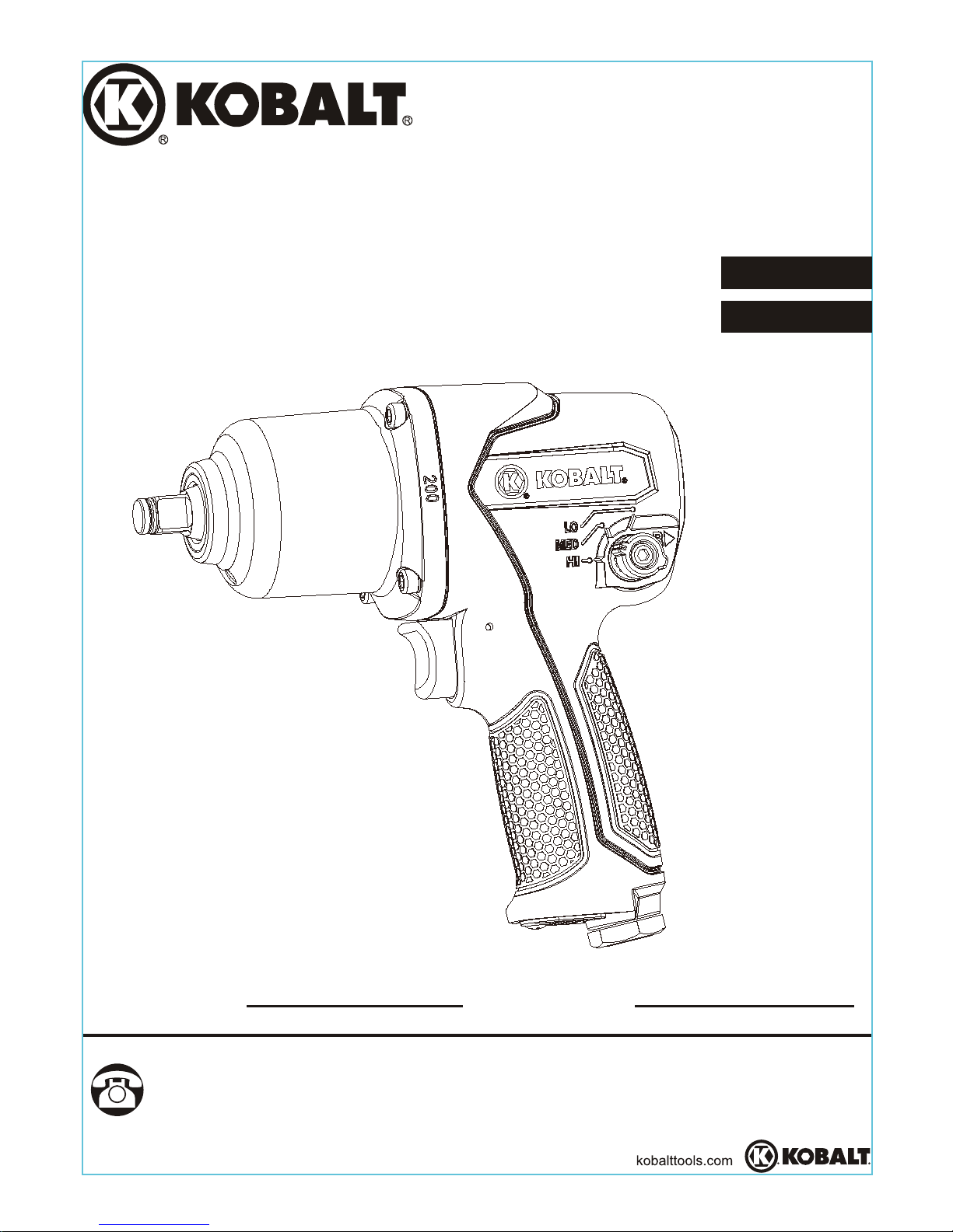
3/8 IN. AIR
IMPACT WRENCH
ITEM #0402536
KOBALT and the K & Design are registered
trademarks of LF, LLC. All rights reserved.
MODEL #SGY-AIR141
® ®
ATTACH YOUR RECEIPT HERE
Serial Number Purchase Date
Questions, problems, missing parts? Before returning to your retailer, call
our customer service department at 1-888-3KOBALT, 8 a.m. - 8 p.m., EST,
Monday - Friday.
1
Français p. 15
Español p. 30
Page 2
TABLE OF CONTENTS
2
Safety Information ............................................................................................... 3
Product Specifications .......................................................................................... 3
Package Contents ............................................................................................... 8
Preparation .......................................................................................................... 9
Assembly Instructions .......................................................................................... 9
Operating Instructions ........................................................................................ 11
Care and Maintenance ....................................................................................... 12
Troubleshooting .................................................................................................. 13
Warranty ............................................................................................................. 13
Replacement Parts List ...................................................................................... 14
IMPORTANT: To operate correctly, this tool requires airflow that is at least 4.5 cubic feet per
minute (CFM) at 90 pounds per square inch (PSI). Check the specifications of your air compressor
to be sure that it can support both the minimum CFM and PSI required. An air hose may cause
up t0 15 PSI drop in pressure, so you may need to set the output higher to maintain the required
pressure at the tool.
de maintenir un niveau adéquat.
IMPORTANTE: Para funcionar de manera correcta, esta herramienta requiere un flujo de aire de
por lo menos 4,5 pies cúbicos por minutos (CFM por sus siglas en inglés) para 90 libras por
pulgada cuadrada(PSI, por sus siglas en inglés). Revise las especificaciones de su compresora
de aire para asegurarse de que puede soportar tanto los CFM como las PSI mínimas requeridas.
Una manguera de aire comprimido puede causar una caída de hasta 15 PSI en la presión, de
manera que puede necesitar configurar la potencia más alta para mantener la presión requerida
en la herramienta.
IMPORTANT : Cet outil nécessite un débit d'air d'au moins 4,5 pi par minute à une pression de
3
3
aux exigencies minimales (pi /min et lb/psi ). L'utilisation d'un tuyau à air peut entraîner une chute
2
90 lb/psi . Vérifiez les spécifications de votre compresseur d'air afin de vous assurer qu'il satisfait
2
de pression de jusqu'à 15 lb/psi . Il peut donc s'avérer nécessaire d'augmenter la pression afin
2
4.5
CFM90PSI
Tool Requirements
Exigences relatives aux outils
Requisitos de herramientas
@
Page 3
3
SAFETY INFORMATION
Please read and understand this entire manual before attempting to assemble, operate
or install the product. If you have any questions regarding the product, please call
customer service at 1-888-3KOBALT, 8:00 a.m.-8:00 p.m., EST, Monday-Friday.
Improper operation or maintenance of this product could result in serious injury and
property damage. Read and understand all warnings and operation instructions
before using this equipment. When using air tools, basic safety precautions should
always be followed to reduce the risk of personal injury.
WARNING
WARNING
SPECIFICATIONS
3/8 IN.
10,000 RPM
200 FT.-LBS.
5.8 CFM
1/4 IN. NPT
3/8 IN.
90 PSI
COMPONENT
SQUARE DRIVE
FREE SPEED
MAXIMUM TORQUE
AVERAGE AIR CONSUMPTION
AIR INLET
AIR HOSE
WORKING PRESSURE
PRODUCT SPECIFICATIONS
SOME DUST CREATED BY PAINT SPRAYING, POWER SANDING, SAWING,
GRINDING, DRILLING, AND OTHER RELATED ACTIVITIES KNOWN TO THE
STATE OF CALIFORNIA TO CAUSE CANCER, BIRTH DEFECTS, AND OTHER
REPRODUCTIVE HARM. A LISTING OF CHEMICALS CAN BE OBTAINED FROM
www.oehha.ca.gov UNDER PROPOSITION 65. SOME EXAMPLES OF THESE
CHEMICALS ARE:
YOUR RISK FROM THESE EXPOSURES VARIES, DEPENDING ON HOW OFTEN
YOU DO THIS TYPE OF WORK. TO REDUCE YOUR EXPOSURE TO THESE
CHEMICALS WORK IN A WELL VENTILATED AREA, AND WORK WITH APPROVED
SPECIALLY DESIGNED TO FILTER MICROSOPIC PARTICLES.
LEAD FROM LEAD BASED PAINTS
PRODUCTS
CRYSTALLINE SILICA FROM BRICKS, CEMENT AND OTHER MASONRY
ARSENIC AND CHROMIUM FROM CHEMICALLY TREATED LUMBER
SAFETY EQUIPMENT, SUCH AS A RESPRIATOR OR DUST MASKS WHICH ARE
Page 4
RISK OF EYE OR HEAD INJURY
WHAT COULD HAPPEN HOW TO PREVENT IT
This particular air powered tool can be
capable of propelling materials such as
fasteners, metal chips, sawdust, and
other debris at high speed which could
result in serious injury.
Compressed air can be hazardous and
propel objects and other particles that
can cause injury to soft tissue areas of
the body, such as eyes and ears.
Particles or objects propelled by the
stream can cause injury.
Tools attachments can become loose
or break and fly apart propelling articles
at the operator and others in the work
area.
Always wear ANSI approved z87.1
safety glasses with side shields.
Never leave operating tool unattended.
Disconnect air hose when tool is not in
use, and place in a safe area.
For additional protection use an
approved face shield in addition to
safety glasses.
Make sure that any attachments are
securely fastened and properly
assembled before use.
WAR
NING
Always use the tool at a safe distance
from others in the work area and ensure
the work area is safe at all times.
WHAT COULD HAPPEN HOW TO PREVENT IT
WAR
NING
An impact wrench would be capable of
generating sparks, which would result
in ignition of flammable materials.
RISK OF FIRE OR EXPLOSION
Never operate tools near flammable
substances such as gasoline, naphtha,
cleaning solvents, etc.
Work in a clean, well ventilated area
free of combustible materials.
Never use oxygen, carbon dioxide or
other bottled gasses as a power source
for air tools.
4
SA
FETY INFORMATION
WHAT COULD HAPPEN HOW TO PREVENT IT
WAR
NING
RISK OF LOSS OF HEARING
Always wear ANSI S3.19 hearing
protection.
Exposure to noise produced from the
operation of air tools can lead to
permanent hearing loss.
Page 5
5
SAFE
TY INFORMATION
Tools which contain moving elements,
or drive other moving parts, such as
impact sockets, can become entangled
in hair, clothing, jewelry and other loose
objects, resulting in severe injury.
WHAT COULD HAPPEN HOW TO PREVENT IT
WAR
NING
RISK OF ENTANGLEMENT
Do not wear loose clothing, jewelry, or
anything that may get caught or tangled
when using tool.
Remove any jewelry which may be
caught by the tool.
Always keep hands and body parts
away from moving parts
Always wear proper fitted clothing and
other properly fitted safety equipment
when using this tool.
WHAT COULD HAPPEN HOW TO PREVENT IT
WAR
NING
RISK OF CUT OR BURNS
Keep the working part of the tool away
from hands and body.
An impact wrench is capable of causing
serious injury if operated in an improper
way, or used in a manner which is not
intended for the tool.
WHAT COULD HAPPEN HOW TO PREVENT IT
WAR
NING
RISK OF ELECTRIC SHOCK
Air tools accessories such as impact
sockets that come into contact with
hidden electrical wiring could cause
electrocution or death.
Thoroughly investigate the work
piece/area for possible hidden wiring
before performing work.
Using air tools to attached electrical
wiring can result in electrical shock,
electrocution, or death.
This tool is not provided with an
insulated gripping surface. Contact with
a “live” wire will also make exposed
metal parts of the tool “live” and can
result in electrical shock, electrocution
or death.
Never use tools to attached electrical
wiring while energized.
Avoid body contact with grounded
surfaces such as pipes, radiators,
refrigerators, and ranges. There is
an increased risk of electrical shock if
your body is grounded.
Page 6

6
SAFETY INFORMATION
WHAT COULD HAPPEN HOW TO PREVENT IT
WARNING
RISK OF PERSONAL INJURY
A tool left unattended, or with the air
hose attached, can be activated by
unauthorized persons leading to their
injury or injury to others.
Air tools can propel fasteners or other
materials throughout the work area.
Always make sure to remove the
wrench key before operating. A wrench
key that is left attached to a rotating
part of the tool increases the risk of
personal injury.
Using inflator nozzles for duster
applications can cause serious injury.
Air tools can become activated by
accident during maintenance or tool
changes.
Air tools can cause the workpiece to
move upon contact, leading to injury.
Remove air hose when tool is not in use
and store tool in secure location away
from reach of children and untrained
users.
Use only parts, fasteners and accessories
recommended by the manufacturer.
Keep work area clean and free of
clutter. Do not allow children to operate
tool, and keep children away from the
work area.
Keep work area well lit.
Remove adjusting keys and wrenches
before turning the tool on.
DO NOT use inflator nozzles for duster
applications.
Remove air hose to lubricate or add
impact sockets to the tool.
Never carry the tool by the air hose.
Always carry the tool by the handle.
Avoid unintentional starting. Never carry
the tool with the trigger depressed or
engaged.
Only an authorized service
representative should do repair
servicing.
Use clamps or other devices to prevent
movement.
Loss of control of the tool can lead to
injury to self of others in the work area.
Never use the tool while using drugs or
alcohol.
Before changing accessories, when
making repairs, or when tool is not in
use, always first shut off air supply and
release / drain air pressure from hose.
Then disconnect tool from air supply or
hose and store in a safe location.
Page 7

7
SAFETY INFORMATION
Loss of control of the tool can lead to
injury to self of others in the work area.
Poor quality, improper or damaged
tools and attachments can fly apart
during operation, propelling particles
through the work area causing serious
injury.
Improperly maintained tools and
accessories can cause serious injury.
There is a risk of bursting if the tool is
damaged.
Keep proper footing at all times. Do not
overreach, as slipping, tripping, and or
falling can be a major cause of serious
injury and or death. Be aware of
excess air hose and power plugs in the
working area or work surface.
Keep handles dry, clean and free from
oil/grease.
Stay alert. Watch what you are doing.
Use common sense. Do not operate
tool when you are tired.
Always use tools attachments rated for
the speed of the power tool.
Never use tools, which have been
dropped, impacted, or are damaged.
Use only impact grade sockets with
this tool.
Do not apply excessive force to the tool;
let the tool perform the work.
Maintain the tool and accessories
with care.
Keep tools clean properly oiled for best
and safest performance.
Check for misalignment or binding of
moving parts, breakage of parts and
any other condition that affects the
tool's operation. If damaged, have the
tool serviced before using.
Never use a tool that is leaking air, has
missing or damaged parts, or requires
repairs.
Wiping or cleaning rages and other
flammable waste materials that may
have been used on tool must be placed
in a tightly closed metal container, and
disposed of in a proper manner.
WHAT COULD HAPPEN HOW TO PREVENT IT
WARNING
RISK OF PERSONAL INJURY
Page 8

PACKAGE C O N T E N T S
8
DESCRIPTION
3/8 in. Air Impact Wrench
Anvil
Trigger
Torque Setting Switch
Air Inlet
Weep Hole
QUANTITY
1
1
1
1
1
1
PART
A
B
C
D
E
F
There is a risk of bursting if the tool is
damaged.
Use of an accessory not intended for
use with the specific tools increases the
risk of injury to operator and anyone
the work area.
Use of an accessory not intended for
use with the specific tools increases the
risk of injury to persons.
Follow lubrication instructions for best
and safest operation.
Follow assembly and repair instructions
on how to properly change accessories.
WHAT COULD HAPPEN HOW TO PREVENT IT
WA RN IN G
RISK OF PERSONAL INJURY
WHAT COULD HAPPEN HOW TO PREVENT IT
WA RN IN G
INHALATION HAZARD
Abrasive tools, such as grinders,
sanders and cut-off tools generate dust
and abrasive materials, which can be
harmful to human lungs and respiratory
system.
Some materials such as adhesives and
tar contain chemicals whose vapors
could cause serious injury with
prolonged exposure.
Always wear properly fitting facemask
or respirator when using such tools.
Always work in a clean, dry,
well-ventilated area.
SAFETY INFORMATION
Page 9

2
3
1. Remove the air inlet protective cap from the
air inlet (E). (See Figure 1)
ASSEMBLY INSTRUCTIONS
9
2. Mount a male plug (not included) by hand
into the air inlet (E). (See Figure 2)
3. Place 2 - 3 drops of air tool oil (not included)
into the male plug before each use.
(See Figure 3)
1
NOTE Use thread sealant tape (not included) on
the male plug and tighten it with a wrench (not
included) for airtight connection. Do not
overtighten.
PREPARATION
Before beginning assembly of product make sure all parts are present. Compare
parts with packaging contents list and diagram above. If any part is missing or
damaged, do not attempt to assemble the product. Contact the 1-800 customer
service number for replacement parts.
Estimated Assembly Time: 5-10 minutes
Tools Required for Assembly (not included): Adjustable wrench
Page 10

5
4
6
ASSEMBLY INSTRUCTIONS
4. Choose the correct impact socket
(not provided) as needed and mount it onto
the anvil (B). (See Figure 4)
5. If longer reach is necessary, use an extension
bar (not provided) and then mount impact
socket (not provided) onto the bar.
(See Figure 5)
6. Connect air supply hose (not provided) to the
male plug (not provided). Set the working
pressure at 90 PSI for best tool performance.
(See Figure 6)
Only use impact sockets that have an RPM
rating equal to or greater than the tool itself.
WARNING
10
NOTE Working pressure refers to the air line
pressure set to tool when tool is under working
conditions.
Page 11

OPERATING INSTRUCTIONS
1. How to install/tighten threaded fasteners.
Turn torque setting switch (part D) from right to
left to desired torque setting and press trigger
(part C) to engage. The tool anvil (part B) runs
clockwise. (See Figure 1)
2. How to install/tighten threaded fasteners.
Turn torque setting switch (part D) from left to
right to desired torque setting and press trigger
(part C) to engage. The tool anvil (part B) runs
counterclockwise. (See Figure 2)
When turn the torque setting switch (D) slowly
forward, the sound of clicks will be detected. The
clicks do not denote a specific power output but
are only for reference. When the switch arrow
points to “Lo”, it stands for the least amount of
power, which is suitable for just mounting
threaded fasteners. When the switch arrow points
to “Hi”, it stands for the most amount of power,
which is for tightening threaded fasteners from
workpiece with ease. In reverse, the tool also has
the function of gear, which is suitable for removing
screws of different specifications. Please choose
the appropriate torque needed on the workpiece.
(See figure 3)
This tool features a power regulator valve.
NOTE
Setting Torque in Forward Torque in Reverse
LO Click
100 ft-lbs (+/-10%)
180 ft-lbs (+/-10%)
200 ft-lbs (+/-10%)
180 ft-lbs (+/-10%)
200 ft-lbs (+/-10%)
220 ft-lbs (+/-10%)
MED Click
HI Click
11
Page 12

OPERATING INSTRUCTIONS
CARE A ND MAINTENA NCE
An in-line oiler is not provided however recommended to be installed to the air supply
line to increases tool life and keeps the tool in sustained operation. The in-line oiler
should be regularly checked and filled with air-tool oil. Proper adjustment of the
in-line oiler is performed by placing a sheet of paper next to the tool’s exhaust ports
and holding the throttle open approximately 30 seconds. The in-line oiler is properly
set when a light stain of oil collects on the paper. Excessive amounts of oil should be
avoided.
In the event that it becomes necessary to store the tool for an extended period of
time, it should receive a generous amount of lubrication before storing the item. The
tool should be run for approximately 30 seconds to ensure oil has been evenly
Recommended lubricants: For proper care and
maintenance use 3 drops of air tool oil, or any other
Clean the tool all over with a cotton rag after each use.
high-grade turbine oil containing moisture absorbent,
rust inhibitors, metal wetting agents and an EP (extreme
pressure) additive (not included). (See Figure 1)
distributed throughout the tool. The tool should be stored in a clean and dry
environment.
12
1
Storing
Impact Wrench must be well cleaned and lightly lubricated
Store Impact Wrench in a dry and safe place out of reach of children
NOTE
This tool features a weep hole (part F) on
the front protective cover. The weep hole (part F)
allows excess air to be released from the impact
wrench automatically while still lubricating the
tool when the proper lubrication instructions are
followed. (See figure 4)
Page 13

THREE-YEAR LIMITED WARRANTY
13
1. Flush the tool with air-tool oil or gum
solvent.
2. Lubricate the tool.
3. Adjust the regulator on the tool to
maximum setting.
Adjust the compressor regulator to tool
maximum of 90 PSI.
4. Tighten and seal hose fittings if leaks are
found. Use sealing tape.
5. Be sure the hose is the proper size.
Long hose or tools using large volumes
of air may require a hose with an I.D. of
1/2 in. or larger depending on the total
length of the hoses.
Do not use a multiple number of hoses
connected together with quick-connect
fittings. This causes additional pressure
drops and reduces the tool power.
Directly connect the hoses together.
6. Replace rotor blade.
7. Water in tank; drain tank. (See air
compressor manual). Oil tool and run
until no water is evident. Oil tool again
and run 1-2 seconds.
Tool runs
slowly or will
not operate
1. Grit or gum in tool.
2. No oil in tool.
3. Low air pressure.
4. Air hose leaks.
5. Pressure drops.
6. Worn rotor blade.
7. Moisture blowing
out of tool exhaust.
PROBLEM
TROUBLESHOOTING
CORRECTIVE ACTIONPOSSIBLE CAUSE
This tool is warranted by the manufacturer to the original purchaser from the original
purchase date for three (3) years subject to the warranty coverage described herein.
This tool is warranted to the original user to be free from defect in material and
workmanship. If you believe that a tool is defective, return the tool, with proper proof
of purchase to the point of purchase. If it is determined that the tool is defective and
covered by this warranty, the distributor will replace the tool or refund the
purchase price.
This warranty is void if: defects in materials or workmanship or damages result from
repairs or alterations which have been made or attempted by others or the
unauthorized use of nonconforming parts; the damage is due to normal wear,
damage is due to abuse (including overloading of the tool beyond capacity), improper
maintenance, neglect or accident; or the damage is due to the use of the tool after
partial failure or use with improper accessories or unauthorized repair or alteration.
This warranty gives you specific legal rights, and you may also have other rights that
vary from state to state.
For warranty questions, call our customer service department at 1-888-3KOBALT,
8:00 a.m.-8:00 p.m. EST, Monday-Friday.
Page 14

REPLACEMENT PARTS LIST
For replacement parts, call our customer service department at 1-888-3KOBALT,
8:00 a.m.-8:00 p.m., EST,
Monday-Friday.
Description Qty.Part NO.
25
26
27
28
30
31
32
33
34
35
36
37
38
39
40
41
42
43
44
45
47
E
C
1
1
6
1
1
1
1
1
2
1
1
1
1
1
1
1
1
1
1
1
1
1
1
Rotor oil seal
Front end plate
Rotor blade
Rotor
Trigger
Pin 2.5 × 25
Soft grip
Reverse valve
O-ring 10.6 × 1.8
Reverse valve bushing
Reverse valve knob Ⅱ
Screw M5 × 12
Screw M4 × 8
Housing
Throttle valve bushing
Valve stem
Soft grip
Reverse valve spring
Air inlet
Dust cover
Spring
Detent ball sw=3.175
Air deflector
Part NO. Description Qty.
1
2
3
4
B
6
7
8
9
10
11
12
13
D
F
15
16
17
18
19
20
21
22
23
1
1
1
1
1
2
2
1
1
1
1
1
1
1
1
1
1
1
2
1
1
1
4
4
Protector cover
Anvil bushing
Anvil
Hammer pin
Hammer
Hammer cage
Hammer case pilot
Hammer case gasket
Gasket
Bearing R6
Rear end plate
Cylinder Dowel
Cylinder
Grease cap
Spring washer 4
Soft grip
Washer
Socket retainer
O-ring 4.5 × 1.3
Screw M5 × 12
Housing cover
Torque setting switch
Screw M5 × 8
Screw M4 × 18
Printed in China
 Loading...