

Page 1

ITEM #0632868
KOBALT® and the K Design® are registered
trademarks of LF, LLC. All Rights Reserved.
ATTACH YOUR RECEIPT HERE
Serial Number Purchase Date
Questions, problems, missing parts? Before returning to your retailer, call our customer
service department at 1-888-3KOBALT (1-888-356-2258), 8 a.m. - 8 p.m., EST,
Monday - Friday.
AB15125B
1
7 IN. BOX
TILE SAW
MODEL #KWS B7-06
Français p. 30
Español p. 60
kobalttools.com
Page 2
TABLE OF CONTENTS
Product Specications ......................................................................................................... 2
Package Contents ............................................................................................................... 3
Hardware Contents.............................................................................................................. 4
Safety Information ............................................................................................................... 5
Preparation ........................................................................................................................ 10
Assembly Instructions........................................................................................................ 11
Operating Instructions ....................................................................................................... 20
Care and Maintenance ..................................................................................................... 27
Troubleshooting ................................................................................................................ 28
Three-Year Warranty ........................................................................................................ 29
Replacement Parts List .................................................................................................... 29
PRODUCT SPECIFICATIONS
DESCRIPTION SPECIFICATIONS
Power Supply 120 V, 60 Hz
Motor 6.5 A
No Load Speed 3,450 RPM
Blade 7 in. x 5/8 in. (arbor)
Maximum Depth of Cut 1-1/4 in.
Rip Capacity (tile size) 18 in.
Diagonal Capacity (tile size) 12 in.
Bevel Cut Range 0°, 22.5°, 45°
kobalttools.com
2
Page 3
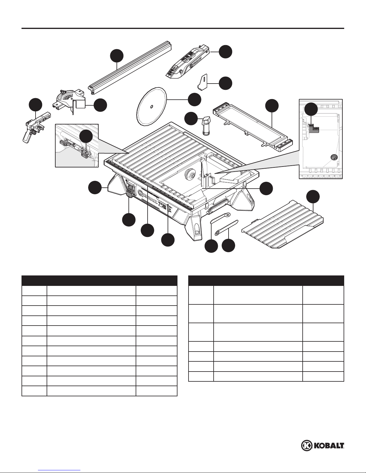
PACKAGE CONTENTS
A
B
R
C
D
Q
G
E
F
J
H
I
K
L
P
O
PART DESCRIPTION QUANTITY
A Locking Lever Assembly 1
B Cord Storage 1
C Miter Gauge 1
D Rip Guide Rail 1
E Blade Guard Assembly 1
F Riving Knife 1
G Overow Drain 1
H Extension Table 1
I Max Water Fill Line 1
J Cutting Wheel 1
K Water Reservoir 1
M
N
PART DESCRIPTION QUANTITY
L Bevel Table
1
(preassembled to tile saw)
M Arbor Nut Wrench
1
(preassembled to tile saw)
N Arbor Wrench
1
(preassembled to tile saw)
O Water Level Indicator 1
P Rip Guide Scale 1
Q Switch 1
R Tile Saw 1
kobalttools.com
3
Page 4
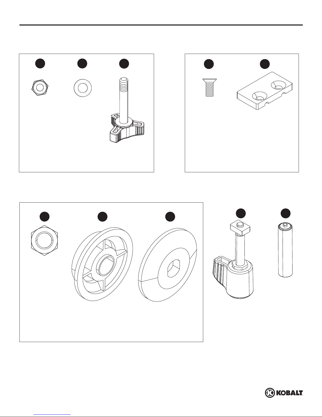
HARDWARE CONTENTS
Qty. 1
Qty. 1
Locking Knob Assembly for Blade Guard
Replacement Part #535113006
AA
Lock Nut
Qty. 1
BB
Washer
Qty. 1
CC
Hex Bolt with Knob
Qty. 1
Blade Locking Assembly
Replacement Part #535113013
Riving Knife Assembly
Replacement Part #535113007
DD
Screw
(preassembled to
tile saw (R))
Qty. 2
(preassembled to
EE
Fixing Plate
tile saw (R))
Qty. 1
FF
Arbor Nut
(preassembled
to tile saw (R))
Qty. 1
GG
Inner Washer
(preassembled to
tile saw (R))
HH
Outer Washer
(preassembled to
tile saw (R))
II
Lever
Assembly Knob
Qty. 1
JJ
AAA Batteries
Qty. 2
kobalttools.com
4
Page 5
SAFETY INFORMATION
Please read and understand this entire manual before attempting to assemble, operate, or install the
product.
This manual contains information that relates to PROTECTING PERSONAL SAFETY and
PREVENTING EQUIPMENT PROBLEMS. It is very important to read this manual carefully and
understand it thoroughly before using the product. The symbols listed below are used to indicate this
information.
DANGER
Potential hazard that will result in serious injury or loss of life.
WARNING
Hazard that could result in serious injury or loss of life.
CAUTION
Potential hazard that may result in moderate injury or damage to equipment.
SAFETY RECOMMENDATIONS
These precautions are intended for the personal safety of the operator and others working with
the operator. Failure to follow these instructions may result in a permanent loss of vision, serious
personal or even fatal injury, property damage and/or tool damage. Please take time to read and
understand them. Safety is a combination of common sense, staying alert and knowing how your
saw works.
WARNING
To avoid mistakes that could cause serious injury, DO NOT plug in the saw until you have read and
understood the rules.
BEFORE USE
• For safe handling of this product, the user must have read and understood the instructions for use
before using it for the rst time.
• Observe all safety instructions! If you DO NOT observe the safety instructions you will endanger
yourself and others.
• Keep all instructions for use and safety instructions for future reference.
• Attach the instructions for use, if you pass on the product to someone else.
• KEEP WORK AREA CLEAN. Cluttered areas and benches invite accidents.
• All parts of the product, safety devices in particular, must be correctly installed to ensure faultless
operation.
kobalttools.com
5
Page 6

SAFETY INFORMATION
OPERATION/WORKPLACE
• KEEP GUARDS IN PLACE and in working order.
• REMOVE ADJUSTING KEYS AND WRENCHES. Form the habit of checking to see that keys and
adjusting wrenches are removed from tool before turning it on.
• KEEP CHILDREN AWAY. All visitors should be kept at a safe distance from work area.
• MAKE WORKSHOP CHILDPROOF with padlocks, master switches or by removing starter keys.
• DO NOT FORCE TOOL. It will do the job better and safer at the rate for which it was designed.
• USE THE RIGHT TOOL. DO NOT force tool or attachment to do a job for which it was not designed.
• DO NOT OVERREACH. Keep proper footing and balance at all times.
• REDUCE THE RISK OF UNINTENTIONAL STARTING. Make sure switch is in the Off position
before plugging in.
• DIRECTION OF FEED. Feed work into a cutting disc against the direction of rotation of the blade or
cutter only.
• NEVER LEAVE TOOL RUNNING UNATTENDED. TURN POWER OFF. DO NOT leave tool until it
comes to a complete stop.
• The product may be used only when in good working condition. If the product or part of the
product is defective, have it repaired by an expert.
• ALWAYS follow the applicable national and international safety, health and labor regulations.
• The product may only be used if no defects are found during the inspection. Ensure that any
defective parts are replaced before the product is used again.
• Position the product horizontally on a rigid, even surface with adequate load-bearing capacity.
• DO NOT leave any tools, objects, or cables lying in the working range of the device.
• Ensure that there is sufcient lighting during operation.
• Assume a natural and secure stance when working.
• Make sure that during operation, no body parts or clothing are caught and drawn in by rotating
components.
• The immediate environment must be free of combustible and other ammable or explosive
substances.
• Young people under 18 years of age and users who are not sufciently familiar with its operation
must not use the product.
• Persons unable to safely and carefully use the tool for physical, psychological, and neural reasons
must not use the product.
• Work with caution and only if you are physically t. Working under the effects of fatigue, illness,
alcohol, medication and drugs is irresponsible, as you are unable to use the product safely.
SERVICE
• DISCONNECT TOOLS before servicing or when changing accessories, such as cutting discs.
• Have your electrical tool repaired only by qualied technicians, using only genuine spare parts. This
will maintain the safety of the electrical tool.
• DO NOT USE IN A DANGEROUS ENVIRONMENT. DO NOT use power tools in damp or wet
locations, or expose them to rain. Keep work area well lit.
• MAINTAIN TOOLS WITH CARE. Keep tools sharp and clean for best and safest performance.
• Follow instructions for lubricating and changing accessories.
kobalttools.com
6
Page 7

SAFETY INFORMATION
• CHECK FOR DAMAGED PARTS. Before further use of the tool, a guard or other part that is
damaged should be carefully checked to determine that it will operate properly and perform its
intended function. Check for alignment of moving parts, binding of moving parts, breakage of parts,
mounting and any other conditions that may affect operation. A guard or other part that is damaged
should be properly repaired or replaced.
• Only the maintenance work and troubleshooting activities described in these instructions may be
carried out. All other work must be carried out by an expert.
• Conversions, unauthorized modications, and the use of non-approved parts are prohibited.
PRODUCT-SPECIFIC SAFETY WARNINGS
• Make sure that you ALWAYS stand to the side of the cutting disc.
• WEAR PROPER APPAREL. DO NOT wear loose clothing, gloves, neckties, rings, bracelets or other
jewelry that may get caught in moving parts. Nonslip footwear is recommended. Wear protective hair
covering to contain long hair.
• ALWAYS USE SAFETY GLASSES. Also use face or dust mask if cutting operation is dusty.
Everyday eyeglasses only have impact-resistant lenses; they are NOT safety glasses.
• USE RECOMMENDED ACCESSORIES. Consult the owner's manual for recommended
accessories. The use of improper accessories may cause risk of injury.
• NEVER STAND ON TOOL. Serious injury could occur if the tool is tipped or if the cutting tool is
unintentionally contacted.
• Use only cutting discs that are suitable for the product.
• Only use cutting discs in good working condition. Remove damaged or worn cutting discs
immediately.
• NEVER use segmented cutting discs.
• Faults in the machine, including guards or diamond discs, should be reported as soon as they are
discovered. NEVER use the machine without the guard in position.
• DO NOT twist or bend workpieces.
• NEVER cut several workpieces simultaneously. DO NOT cut bundles made of several individual
pieces. A workpiece can get caught in the cutting disc and y out of control.
• NEVER cut workpieces on which there are ropes, cords, bands, cables, or wires containing such
materials.
• Make regular checks to ensure that the cutting disc is correctly fastened.
• Make sure that during the cutting operation, an adequate quantity of cooling water reaches the
cutting surfaces of the disc at all times.
• NEVER cut wood or metal with this saw.
• ALWAYS maintain sufcient distance from the cutting disc. Switch off the product and wait until the
cutting disc stops before removing workpieces, residual material, etc., from the work area.
• ALWAYS pull out the main plug (disconnect the product from its power supply) before commencing
work on the product.
• A cutting disc can cause injuries, even when stationary! Use protective gloves to change the cutting
disc.
• NEVER use lateral counter pressure to bring the cutting disc to a standstill after switching off the
drive.
• Replace table insert when worn.
• Use only diamond discs recommended by the manufacturer.
• NEVER use blades on this machine.
kobalttools.com
7
Page 8
SAFETY INFORMATION
• Use only diamond discs for which the maximum possible speed is not less than the maximum
spindle speed of the tool and the material to be cut.
• Maximum size of working piece should be 10 sq. ft. (1 m2).
• This tile saw should only be used at temperatures between 59°F - 80°F.
• USE PROPER EXTENSION CORD. Make sure your extension cord is in good condition. When
using an extension cord, be sure to use one heavy enough to carry the current your product
will draw. An undersized cord will cause a drop in line voltage, resulting in loss of power and
overheating. Next page shows the correct size to use depending on cord length and nameplate
ampere rating. If in doubt, use the next heavier gauge. The smaller the gauge number, the heavier
the cord.
STORAGE AND TRANSPORT
• ALWAYS store the product in a dry place.
• Store the product in a frost-free place.
• Protect the product from damage during transport.
• Keep the product away from children. Store the product in a place where it is safe from children and
unauthorized persons.
RESIDUAL RISKS
Even when the product is used properly and in compliance with all the safety precautions in these
instructions for use, the following residual risks can arise:
• Touching the cutting disc in the exposed area.
• Reaching into the spinning cutting disc.
• Rebound from workpieces and workpiece parts.
• Cutting disc breaks.
• Faulty cutting disc diamond attachment being ung out.
• Hearing damage through failure to wear the requisite hearing protection.
WARNING
For your own safety, read instruction manual before operating saw.
• Wear eye protection.
• Use splash guard for every operation for which it can be used.
• Disconnect saw before servicing, when changing cutting wheels and cleaning.
• Use tool only with smooth edge cutting wheels free of openings and grooves.
• Replace damaged cutting wheel before operating.
• DO NOT ll water tank above water ll line.
WARNING
The tool is loud and the sound can cause hearing damage. ALWAYS wear ear protection to help
prevent hearing damage and loss. Failure to comply may result in moderate injury.
READ OPERATOR’S MANUAL
To reduce the risk of injury, user must read and understand operator’s manual before using this
product.
•USESAFETYGOGGLESANDEARPROTECTION.
•ALWAYS WEAR EYE PROTECTION THAT CONFORMS WITH CUL REQUIREMENTS.
FLYING DEBRIS can cause permanent eye damage.
kobalttools.com
8
Page 9
SAFETY INFORMATION
USE DUST MASK
Some dust created by sawing contains chemicals that are known to cause cancer, birth defects
or other reproductive harm. Some examples of these chemicals come from lead-based paints,
crystalline silica from bricks, cement and other masonry products, arsenic and chromium from
chemically treated lumber. To reduce exposure to these chemicals, work in a well-ventilated area with
approved safety equipment, such as dust masks that are specially designed to lter out microscopic
particles.
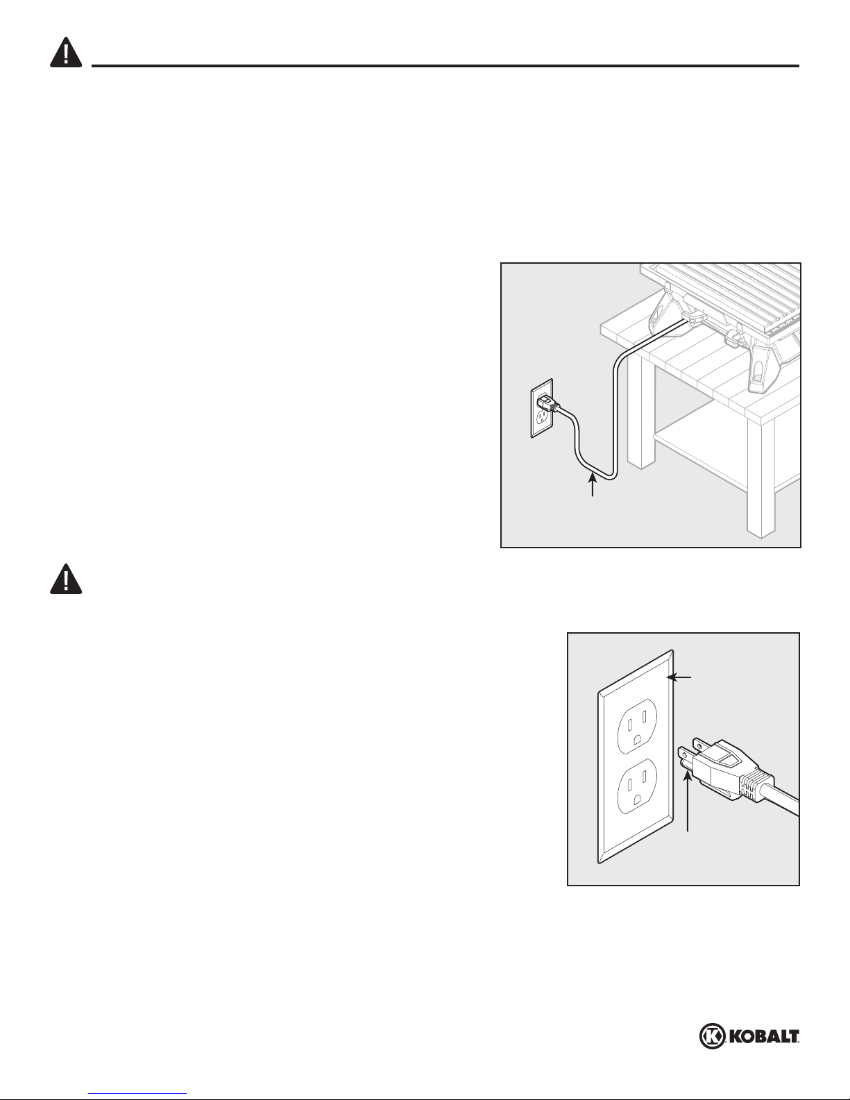
POSITION OF TILE SAW
• To avoid the possibility of the appliance plug or
receptacle getting wet, position tile saw to one side
of a wall-mounted receptacle to prevent water from
dripping onto the receptacle or plug. The user should
arrange a "drip loop" in the cord connecting the saw
to a receptacle. The "drip loop" is the part of the cord
below the level of the receptacle, or the connector if an
extension cord is used, to prevent water traveling along
the cord and coming into contact with the receptacle.
• If the plug or receptacle does get wet, DO NOT unplug
the cord. Disconnect the fuse or circuit breaker that
supplies power to the tool. Then unplug and examine for
presence of water in the receptacle.
Drip loop
ELECTRICAL SAFETY
CAUTION
In all cases, verify that the outlet in question is properly grounded. If you are not sure, have a licensed
electrician check the outlet.
GROUNDING INSTRUCTIONS
In the event of a malfunction or breakdown, grounding provides
a path of least resistance for electric current to reduce the risk of
Grounded
outlet box
electric shock. This tool is equipped with an electric cord that has
an equipment-grounding conductor and a grounding plug. The plug
must be plugged into a matching outlet that is properly installed
and grounded in accordance with all local codes and ordinances.
DO NOT modify the plug provided. If it will not t the outlet, have
the proper outlet installed by a qualied electrician.
Grounding pin
Improper connection of the equipment-grounding conductor can
result in a risk of electric shock. The conductor with a green outer
surface, with or without yellow stripes, is the equipment-grounding
conductor. If repair or replacement of the electric cord or plug is necessary, DO NOT connect the
equipment-grounding conductor to a live terminal. Check with a qualied electrician or service
technician if the grounding instructions are not completely understood, or if in doubt as to whether the
tool is properly grounded. Use only three-wire extension cords that have three-prong grounding plugs
and three-pole receptacles that accept the tool’s plug, as shown. Repair or replace a damaged or
worn cord immediately.
kobalttools.com
9
Page 10

SAFETY INFORMATION
WARNING
• Use the proper extension cord. Make sure to use an extension cord that is heavy enough to carry
the current required by the tool. An undersized cord will cause a drop in line voltage, resulting in loss
of power and overheating of the tool.
• Use the extension cord only for intended purpose. DO NOT pull the extension cord to remove it from
the power socket.
Recommended size for extension cords
Amperage Rating of the Tool
(120 V Circuit Only)
25' (7.6 m) 50' (15.2 m) 100' (30.5 m) 150' (45.7 m)
Total Length of the Extension Cord
MORE THAN NOT MORE THAN MINIMUM GAUGE FOR THE EXTENSION CORD (AWG)
0 6 18 16 16 14
6 10 18 16 14 12
10 12 16 16 14 12
12 16 14 12 Not recommended
KEEP THESE INSTRUCTIONS FOR FUTURE REFERENCE.
PREPARATION
Before beginning assembly of product, make sure all parts are present. Compare parts with package
contents list and hardware contents list. If any part is missing or damaged, do not attempt to
assemble the product.
Tools Required for Assembly (not included): 8mm wrench, Phillips screwdriver
kobalttools.com
10
Page 11

ASSEMBLY INSTRUCTIONS
UNPACKING
This product requires assembly.
• Carefully lift the saw from the carton and place on a level work surface.
WARNING
• DO NOT use this product if any parts in the Package Contents and Hardware Contents lists are pre-
assembled to your product when you unpack it (apart from those specied as being pre-assembled).
Parts on this list are not assembled to the product by the manufacturer and require customer
installation. Use of a product that may have been improperly assembled could result in serious
personal injury.
1. Inspect the tool carefully to make sure no breakage or damage occurred during shipping.
2. DO NOT discard the packing material until you have carefully inspected and operated
the tool.
3. The saw is factory set for accurate cutting. After assembling it, check for accuracy.
4. If any parts are damaged or missing, please call 1-888-3KOBALT (1-888-356-2258) for assistance.
WARNING
• If any parts are damaged or missing, DO NOT operate this tool until the parts are replaced. Use of
this product with damaged or missing parts could result in serious personal injury.
• DO NOT attempt to modify this tool or create accessories not recommended for use with this tool.
Any such alteration or modication is misuse and could result in a hazardous condition leading to
possible serious personal injury.
• DO NOT connect to power supply until assembly is complete. Failure to comply could result in
accidental starting and possible serious personal injury.
MOUNTING HOLES
This tile saw can be mounted to an optional stand (Item #0544098, sold separately at www.lowes.
com). This stand can be shared with the Kobalt 7 in. sliding saw (Item #0632871, sold separately).
1. The tile saw (R) can also be mounted to a rm
supporting surface such as a workbench. Four bolt
R
holes have been provided in the saw’s base for this
purpose. Each of the four mounting holes should be
bolted securely using M6 socket bolts, lock washers,
and nuts (not included). Bolts should be of sufcient
length to accommodate the saw base, lock washers,
hex nuts and the thickness of the workbench. Tighten
all four bolts securely.
Carefully check the workbench after mounting to
make sure that no movement can occur during use.
If any tipping, sliding, or walking is noted, secure the
workbench to the oor before operating.
kobalttools.com
11
Page 12

ASSEMBLY INSTRUCTIONS
Tile Cutting Wheel
For maximum performance and safety, it is recommended that you use the 7 in. cutting wheel provided
with your saw. Additional cutting wheels are sold separately.
WARNING
• DO NOT use cutting wheels rated less than the no load speed of this tool. Failure to heed this
warning could result in personal injury. DO NOT use a wheel with cracks, gaps, or teeth.
Installing the Tile Cutting Wheel
WARNING
• A 7 in. tile cutting wheel is the maximum wheel capacity of the saw. NEVER use a wheel that is
too thick to allow wheel washer to engage with the ats on the spindle. Larger wheels will come
in contact with the splash guard, while thicker wheels will prevent the wheel bolt from securing
the wheel on the spindle. Either of these situations could result in serious accident and can cause
serious personal injury.
1. Unplug saw and remove bevel table (L).
2. Place arbor nut wrench (M) on arbor nut (FF), then
slide arbor wrench (N) onto arbor.
3. Holding arbor wrench (N) rmly to prevent the wheel
from moving, loosen arbor nut (FF) in a
counterclockwise direction with arbor nut wrench (M).
1
L
2
FF
M
1
2
N
3
M
N
kobalttools.com
12
Page 13

ASSEMBLY INSTRUCTIONS
4. Remove arbor nut (FF) and outer washer (HH),
leaving the inner washer on the arbor.
WARNING
•ALWAYS install the inner wheel washer before placing
wheel on arbor. Failure to do so could cause an
accident since the wheel will not tighten properly.
NEVER use wheels that have openings, grooves, or
teeth on this tool.
5. Place cutting wheel (J) onto arbor with arrows
on wheel going in the counterclockwise direction.
4
5
HH
J
FF
6. Replace outer washer (HH). The double “D” ats on
washers align with ats on arbor. Replace arbor nut
(FF) on arbor. Make sure at side of arbor nut
touches outer washer (HH).
7. Using arbor nut wrench (M) and arbor wrench (N),
tighten arbor nut securely.
6
7
M
HH
FlatsFlats
FF
N
kobalttools.com
13
Page 14

ASSEMBLY INSTRUCTIONS
2
1
Installing Blade Guard Assembly
1. Loosen and remove screws (DD) and xing plate
(EE) with a Phillips screwdriver (not included).
2. Place riving knife (F) onto the mounting area on
table. Reinstall screws (DD) through xing plate
(EE) and table and into riving knife (F).
1
2
2
DD
EE
DD
EE
F
3. To maximize cut quality, align riving knife (F)
with the cutting wheel (J). Tighten screws (DD).
Note: Rip guide rail (D) can be used as alignment
tool if needed.
14
3
F
1
1
J
DD
D
kobalttools.com
Page 15

ASSEMBLY INSTRUCTIONS
4. Slide blade guard assembly (E) over riving knife (F)
and align holes in blade guard assembly (E) with slot
in the riving knife (F).
5. Place lock nut (AA) onto hollow hex-shaped area on
blade guard assembly (E) and hold in place.
4
E
F
5
E
AA
6. Thread hex bolt with knob (CC) through
washer (BB), blade guard assembly (E) and riving
knife (F). Tighten to the desired height.
Note: ALWAYS adjust the blade guard horizontally to
the table and slightly above tile thickness. Blade guard
should not touch the tile.
15
6
CC
BB
E
1
F
2
kobalttools.com
Page 16

ASSEMBLY INSTRUCTIONS
Installing the Laser Batteries
1. On top of blade guard assembly (E), pull cover of
battery compartment in direction of arrow molded
into the battery cover to remove.
2. Place two AAA batteries (JJ) into battery
compartment. Take care to insert batteries with
the correct polarity as indicated inside battery
compartment. Replace the cover.
1
E
2
2
JJ
E
1
Adjusting the Alignment of the Laser
1. Turn on laser by pressing button on blade guard
assembly (E). Rotate the knob on the right of
blade guard assembly (E) until laser beam aligns
with 0 scale. Press button again to turn off the
laser.
16
1
0 Scale
0 Scale
kobalttools.com
E
1
2
2
3
Page 17

ASSEMBLY INSTRUCTIONS
Installing the Extension Table
1. Align two supporting rod pins with two mounting
holes on tile saw (R) and insert until the
extension table (H) hangs on edges of main
worktable. Rotate knob clockwise to lock
extension table (H) in place.
Note: Following the same procedure, extension
table could be also be mounted on the left or right
side of main worktable.
Installing the Rip Guide
1. Place lever assembly knob (II) in slot of locking
lever assembly (A).
Note: The lever assembly knob (II) can be installed
on either side of the lever assembly (A) depending
on if the rip guide rail (D) will be used on the left
or right side of the cutting wheel (J). The lever
assembly knob (II) must be installed opposite of at
side of rip guide rail (D).
1
1
R
1
2
H
1
II
D
A
II
D
A
2. Align rectangle nut on locking lever assembly (A)
with the slot on rip guide rail (D).
Note: If rectangle nut interferes with the end of
guide rail, rotate hex nut to another position.
2
D
A
kobalttools.com
17
Page 18

ASSEMBLY INSTRUCTIONS
2
3. Slide locking level assembly (A) until the end of
rip guide rail (D) is ush with the machining area
on locking lever assembly. Rotate locking level
assembly knob clockwise to lock in place.
Note: The position of locking level assembly knob
can be adjusted by pulling out assembly knob,
rotating to desired position, then pushing back into
position.
4. Place front of rip guide rail (D) on front rail of tile
saw (R). Lower back of rip guide rail (D) to tile
saw (R).
3
4
D
A
1
1
D
R
5. Use rip guide scale (P), located on front of table,
to set rip guide to desired width of cut. Push
locking lever down to secure to saw table.
Note: When securely locked, locking lever should
point downward.
18
5
1
P
kobalttools.com
kobalttools.com
1
Page 19

ASSEMBLY INSTRUCTIONS
Installing the Miter Guide
1. Align groove under miter gauge (C) with grooves
in top of the rip guide rail (D). Push miter guide
onto rip guide to desired operating position.
Note: Slide miter guide off rip guide to remove.
InstallingtheOverowDrain
1. Remove bevel table (L).
1
2
C
1
D
1
L
2. Firmly push overow drain (G) into the hole in
the bottom of the water reservoir (K).
2
G
K
kobalttools.com
19
Page 20

OPERATING INSTRUCTIONS
WARNING
• DO NOT allow familiarity with the tools to make you careless. Remember that a careless fraction of
a second is sufcient to inict serious injury.
• ALWAYS wear eye protection with side shields marked to comply with ANSI Z87.1. Failure to do so
could result in objects being thrown into your eyes, resulting in possible serious injury.
• DO NOT use any attachments or accessories not recommended by the manufacturer of this tool.
The u se of attachments or accessories not recommended can result in serious injury.
APPLICATIONS
You may use this tool for the purpose listed below:
• Straight line cutting operations such as cross cutting, mitering, ripping, and beveling.
Note: This saw is designed to cut man-made tile, pavers, and stone tile products only.
ON/OFF SWITCH
This saw is equipped with a switch that has a
1
built-in locking feature. This feature is intended to prevent
unauthorized and possible hazardous use by children and
others.
ToTurntheSawOn
With the switch key inserted into the switch, lift the
switch to turn ON (I).
ToTurntheSawOff
Press the switch down to turn OFF (O).
ToLocktheSaw
With the saw turned OFF, remove the safety key from
the switch. Store the key in a safe place.
WARNING
• In the event of a power failure or when the tool is not
in use, turn the switch OFF. This action will prevent
the tool from accidentally starting when power returns.
• ALWAYS make sure your workpiece is not in contact
with the cutting wheel before operating the switch to
start the tool. Failure to heed this warning may cause
the workpiece to be kicked back toward the operator and
result in serious personal injury.
• To reduce the risk of accidental starting, ALWAYS make
sure the switch is in the OFF position before plugging
tool into the power source.
OFFOFFONON
1
LOCKEDLOCKED
kobalttools.com
20
Page 21

OPERATING INSTRUCTIONS
FILLING THE RESERVOIR WATER
1. Fill the water reservoir with clean tap water to the
max ll line.
Note: The overow drain prevents overlling.
TO CHANGE RESERVOIR WATER
1. Unplug the saw.
2. Remove the overow drain and empty waste water
into a bucket. DO NOT allow the water to splash
onto the ground or around the machine.
3. Rinse the machine thoroughly.
Note: Make sure there is no debris inside the water
level component compartment.
4. Discard the waste water in accordance with local
regulations.
5. Replace with clean water.
1
2
G
kobalttools.com
21
Page 22

OPERATING INSTRUCTIONS
2
3
USING THE RIP GUIDE
The rip guide can be used on either the left or the right
side of the cutting wheel. The at side of the rip guide
must ALWAYS be facing the cutting wheel. The locking
lever assembly can be repositioned for either side of
the rip guide. Refer to the Rip Guide Installation section
on page 17 if necessary.
• Place the rip guide rail (D) in the desired position using
the rip guide scale (P) located on front of the saw
table.
• To reposition the rip guide, refer to the Rip Guide
Installation section.
The rip guide rail (D) can be adjusted forward and
securely locked for maximum support on large tile.
D
1
1
P
D
2
1
USING THE MITER GAUGE
To adjust angles:
• Attach the miter gauge (C) to the rip guide.
• Loosen the lock knob and move the miter gauge to
the desired position.
• Securely tighten the lock knob.
II
D
C
kobalttools.com
22
Page 23

OPERATING INSTRUCTIONS
MAKING CUTS
• ALWAYS draw the line to be cut on the tile using a marker or grease pencil. If the tile is shiny and
hard-to-mark, place masking tape on the tile and mark the tape.
• A common problem when cutting tile is straying from the marked line. Once you’ve strayed from the
mark, you can not force the wheel back to the line by twisting the tile. Instead, back up and recut the
tile slicing off a small amount of tile until the wheel is back on track.
• To avoid this problem, use the rip guide when making cross cuts, the miter gauge for miter cuts and
the bevel table for making bevel cuts, whenever possible.
• Another problem is cutting difcult material. To prevent chipping of the material at the end of the cut:
rst cut 1-1/2 in. of the material, then turn off the saw; ip the material around 180° and make the
cut.
• Clean the saw blade, rip and miter guides, and bevel table frequently during use. Debris from the cut
material can interfere with the function of the tool.
MAKING A CROSS CUT
Cross cuts are straight 90° cuts. The material is fed
into the saw at a 90° angle to the wheel.
• Using a marker or grease pencil, mark the area to be
cut on material.
D
• Remove the miter gauge.
• Position the rip guide (D) the desired distance from the
wheel for the cut and securely lock the lever.
• Place the material on the table, rmly against the
rip guide.
• Make sure the material is clear of the cutting wheel
before turning on the saw.
• Turn the on/off switch to the ON position.
• Let the cutting wheel build up to full speed and wait
for the wheel to get wet before moving the material
into the wheel.
• Hold the material rmly against the rip guide (D) and
feed the material into the cutting wheel.
When the cut is made, turn the saw OFF. Wait for the
cutting wheel to come to a complete stop before
removing any part of the material.
kobalttools.com
23
Page 24

OPERATING INSTRUCTIONS
MAKING A 45° DIAGONAL CUT
45° Diagonal cuts are also referred to as
“long point-to-long point cuts”.
• Using a marker or grease pencil, mark the area to be
C
cut on material.
• Install the miter gauge (C).
• Adjust miter gauge to 45° using angle scale and
tighten securely with lock knob.
• Position the rip guide rail (D) the desired distance from
the wheel for the cut and securely lock the lever.
• Place the material on the table and rmly against the
rip guide.
• Make sure the material is clear of the cutting wheel
before turning on the saw.
• Turn the on/off switch to the ON position.
• Let the cutting wheel build up to full speed and wait for
the wheel to get wet before moving the material into the wheel.
• Hold the material rmly against the miter guide and slide miter guide along rip guide. Feed the
material into the cutting wheel.
• When the cut is made, turn the saw OFF. Wait for the cutting wheel to come to a complete stop
before removing any part of the material.
D
TO MAKE A MITER CUT
Miter cuts are used for cutting outside and inside
corners on material, decorative chair rail, and base
moulding with the material at any angle to the wheel
C
other than 90°. Miter cuts tend to “creep” during cutting.
This can be controlled by holding the workpiece
securely against the miter guide.
• Using a marker or grease pencil, mark the area to
be cut on material.
• Install the miter gauge (C).
• Position the rip guide rail (D) the desired distance from
the wheel for the cut and securely lock the lever.
• Set the miter guide to desired angle using the miter
guide scale, and tighten securely with lock knob.
• Place the material on the table and rmly against the
rip guide.
• Make sure the material is clear of the cutting wheel before turning on the saw.
• Turn the on/off switch to the ON position.
• Let the cutting wheel build up to full speed and wait for the wheel to get wet before moving the
material into the wheel.
• Hold the material rmly against the miter guide and slide miter guide along rip guide. Feed the
material into the cutting wheel.
• When the cut is made, turn the saw OFF. Wait for the cutting wheel to come to a complete stop
before removing any part of the material.
D
kobalttools.com
24
Page 25

OPERATING INSTRUCTIONS
TO MAKE AN L-CUT
L-cuts are cuts that remove a piece of tile to t in a
corner, around a cabinet, or a piece of moulding and are
made by making two separate cuts.
Note: Only overcut on the bottom or underneath side of
the material being cut.
• Using a marker or grease pencil, mark the area to
be cut on material.
• Remove the miter gauge.
• Position the rip guide rail (D) the desired distance from
the wheel for the cut and securely lock the lever.
• Place the material on the table, rmly against the
rip guide.
• Make sure the material is clear of the cutting wheel
before turning on the saw.
• Turn the on/off switch to the ON position.
• Let the cutting wheel build up to full speed and wait
for the wheel to get wet before moving the material
into the wheel.
• Hold the material rmly against the rip guide and feed
the material into the cutting wheel.
• Make the cut far enough into the material without
over-cutting.
• When the cut is made, turn the saw OFF. Wait for
the cutting wheel to come to a complete stop before
removing any part of the material.
• Turn the material, adjust the rip guide, and make the
second cut along one of the marks. This time overcut
the other line and the cut piece should separate from
the rest of the material.
• When the second cut is made, turn the saw OFF.
Wait for the cutting wheel to come to a complete stop
before removing any part of the material.
D
D
kobalttools.com
25
Page 26

OPERATING INSTRUCTIONS
4
TO MAKE BEVEL CUT
Beveled 22.5° and 45° cuts can be made using the
bevel table.
• Using a marker or grease pencil, mark the area to be
cut on material.
• Remove the rip guide.
• Tilt the bevel table (L).
• On underside of the bevel table, pull down the table
legs into right angles of the plate.
–Use rst notches in legs to rest plate into 22.5° angle.
– Use second set of notches to angle bevel table into
highest 45° angle.
L
1
2
Note: Make sure bevel table is locked rmly in place
2
before beginning cut.
• Turn the on/off switch to the ON position
• Let the cutting wheel build up to full speed and wait
for the wheel to get wet before moving the material
into the wheel.
• Hold the material rmly against the bevel table and
feed the material into the cutting wheel.
• When the cut is made, turn the saw OFF. Wait for
the cutting wheel to come to a complete stop before
removing any part of the material.
ADJUSTMENTS
WARNING
Before performing any adjustment, make sure the tool is unplugged from the power supply and the
switch is in the OFF position. Failure to heed this warning could result in serious personal injury.
TO ADJUST CAM ON LOCKING LEVER ASSEMBLY
Over time the rip guide may become loose. If the rip
guide does not lock securely to the saw table,
adjustment may be required.
• Unplug the saw.
2
3
• Remove the locking lever assembly from the rip guide.
• Using a 8mm hexagonal open end wrench (not
included), loosen the nut securing the cam to the lever
assembly.
• Pull the cam out slightly and rotate the cam one tooth,
1
4
then align the teeth in the cam with the slots in the
side of the locking lever.
• Reinstall the nut and tighten securely.
Note: If the rip guide is still loose, repeat the above
steps as needed.
kobalttools.com
26
Page 27

CARE AND MAINTENANCE
WARNING
• When servicing, use only identical Kobalt replacement parts. Use of any other parts may create a
hazard or cause product damage.
• ALWAYS wear eye protection with side shields marked to comply with ANSI 787.I during product
operation. If operation is dusty, also wear a dust mask.
• DO NOT at any time let brake uids, gasoline, petroleum-based products, penetrating oils, etc., come
in contact with plastic parts. Chemicals can damage, weaken or destroy plastic which may result in
serious personal injury.
Avoid using solvents when cleaning plastic parts. Most plastics are susceptible to damage from various
types of commercial solvents and may be damaged by their use. Use clean cloths to remove dirt, dust,
oil, grease, etc.
LUBRICATION
All of the bearings in this tool are lubricated with a sufcient amount of high grade lubricant for the life
of the unit under normal operating conditions.
CLEANING THE RIP AND MITER GUIDES
During use, the rip and miter guides will become dirty preventing the guides from sliding smoothly. It is
important to clean the saw often.
CLEANING THE SAW
• Unplug the saw.
• Remove the guides and bevel table from the saw.
• Using a small brush and/or water, clean each piece thoroughly removing any trapped debris.
• Remove the overow drain and empty waste water into a bucket. DO NOT allow the water to splash.
onto the ground or around the machine.
• Rinse the machine thoroughly.
• Discard the waste water in accordance with local regulations.
• Replace the drain plug. Tighten securely.
• Dry off the tool.
• Never use water or any other chemical liquids to clean the electrical parts of the machine.
• Keep the ventilation slots clean to prevent overheating of the motor.
• Use a damp soft cloth to clean the water and dust off the tile saw.
kobalttools.com
27
Page 28

TROUBLESHOOTING
If you have any questions regarding the product, please call customer service at 1-888-3KOBALT
(1-888-356-2258).
PROBLEM POSSIBLE CAUSE CORRECTIVE ACTION
Motor not running. No power. 1. Check cable, plug, socket, and fuse.
Motor runs, cutting
disk remains still.
It is difcult to cut
materials.
Cutting wheel runs
irregularly/vibrates.
Cutting wheel is
discolored.
Laser line
projection is hard
to see.
Laser line is not
projecting.
Arbor nut loose. 1. Check the inner washer and outer
washer are seated correctly and then
tighten the arbor nut if necessary.
Tile cutting wheel is dull. 1. Replace the cutting wheel.
1. Cutting wheel warped.
2. Cutting wheel tted incorrectly.
1. Insufcient cooling water.
2. Lateral friction caused by runout.
1. Replace the cutting wheel.
2. Fit the cutting wheel correctly.
1. Fill the basin with sufcient water.
2. Guide workpiece through cutting wheel
more slowly.
1. Light in work area is too bright.
2. Batteries are depleted.
3. Dust or water is on the cover of
aperture.
1. Laser switch is in the "off"
position.
2. Batteries are depleted.
1. Turn down the environment light.
2. Replace the batteries.
3. Clean the dust or water on the cover at
the aperture.
1. Check that the laser switch is in the
"on" position.
2. Replace the batteries.
kobalttools.com
28
Page 29

THREE-YEAR WARRANTY
This tile saw is warranted to the original purchaser from the original purchase date for three (3) years
subject to the warranty coverage described herein.
This tile saw is warranted to be free from defects in material and workmanship. If you believe that
the tile saw is defective at any time during the specied warranty period, simply return the tile saw to
the place of purchase for a free replacement or refund or call 1-888-3KOBALT (1-888-356-2258) for
warranty services.
This warranty is void if: defects in materials or workmanship or damages result from repairs or
alterations which have been made or attempted by others or the unauthorized use of nonconforming
parts; the damage is due to normal wear, damage is due to abuse (including overloading of the tool
beyond capacity), improper maintenance, neglect or accident; or the damage is due to the use of the
tool after partial failure or use of improper accessories or unauthorized repair or alteration.
This warranty gives you specic legal rights, and you may also have other rights that vary from state
to state.
For questions, warranty claims, and/or warranty replacement parts, call our customer service
department at 1-888-3KOBALT (1-888-356-2258).
REPLACEMENT PARTS LIST
For replacement parts, call our customer service department at 1-888-3KOBALT (1-888-356-2258),
8 a.m. - 8 p.m., EST, Monday - Friday.
PART DESCRIPTION PART #
Locking lever assembly 632868001
A
Miter gauge 632868004
C
Rip guide rail 632868002
D
Blade guard 632868005
E
Overow drain 632868012
G
Arbor nut wrench 632868009
M
Arbor wrench 632868010
N
S
T
U
V
W
II
Locking knob assembly
for blade guard
Riving knife assembly 632868007
Switch key 632868008
Bevel Table legs
assembly
Blade Locking Assembly 632868013
Lever assembly knob 632868003
632868006
632868011
E
U
G
W
A
D
S
N
II
M
C
T
V
Printed in China
29
KOBALT® and the K Design® are registered
trademarks of LF, LLC. All Rights Reserved.
kobalttools.com
 Loading...