

Page 1
I(O
Stationary
Air Compressor
Manual
For Kobalt Models
K7060V
K7060HFV K7580V2
For questions concerning this air compressor,
please call: 1-866-242-4298.
Rev. 0305 Printed In USA
Page 2
PAGE
1
2
3
4
5
6
7-8
9-13
14
Safety Guidelines - Definitions
Before Using the Air Compressor
When Installing or Moving the Compressor
Before Each Use
Follow Safety Precautions for Electrical Connection
Plan Ahead to Protect Your Eyes, Hands, Face & Ears
When Operating
Spraying Precautions
Perform These Maintenance Operations
Warning Labels
Glossary
Wiring
Starting the Compressor
Troubleshooting
Parts
Warranty Statement
Page 3
Safety is a combination of common sense, staying alert and knowing how your compressor works.
Read this manual to understand this compressor.
means if safety information is not followed someone will be seriously injured or killed
A
means if safety information is not followed someone could be seriously injured or killed
means if safety information is not followed someone may be seriously injured or killed
Save these instructions
Improper operation or maintenance of this product could result in serious injury and property
damage. Read and understand all warnings and operation instructions before using this compressor.
Before using the air compressor
Things you should know
Air compressors are utilized in a variety of air
system applications. Because air compressors
and other components (hoses, connectors, air
tools, spray guns, etc.) make up a high pressure
pumping system, the following safety pre-
cautions should be observed at all times.
Inspect your work area
1. Keep work areaclean.
2. Cluttered areas and benches invite accidents.
Floors must not be slippery from wax or dust.
Inspect your compressor
Only persons familiar with these rules of
safe operation should use the air
compressor.
1. To reduce the risk of injury from accidental
starting, turn switch off and disconnect the
power before checking it.
1. Read the instruction manual carefully before
attempting to assemble, disassemble or
operate your system. Be thoroughly familiar
with the controls and the proper use of the
equipment.
2. Review and understand all safety instructions
and operating procedures in this manual.
3. Review the maintenance methods for this
compressor (See "Maintaining Your
Compressor" section).
2. If any part is missing, bent or broken in any
way, or any electrical part does not work prop-
edy, keep the compressor off and disconnected.
3. Check hoses for weak or worn condition
before each use, making certain all connections
are secure. Do Not use ifdefect is found.
A
Do not operate compressor if damaged during
shipping, handling or use. Damage may result
in bursting and cause injury or property damage.
D7_,I_[€-]=1__
This compressor is Not designed for and should
not be used in breathing air applications.
Page 1
Page 4
When installing or moving the compressor 1
This compressor is extremely top heavy. The
compressor must be bolted to the floor with
vibration pads before operating to prevent
equipment damage, injury or death. Do Not
tighten bolts completely as this may
cause stress to the tank welds.
To reduce the risk of a dangerous
environment
1. Keep work area well lit.
2. Operate compressor in a well-ventilated
area free from flammable liquids and vapors.
3. Operate compressor in a ventilated area so
that compressor may be propedy cooled and
the surrounding air temperature will not be
more than 100°F.
4. Never use a compressor in a wet
environment.
5. Protect matedal lines and air lines from
damage or puncture. Keep hose and
wires away from sharp objects, chemical
spills, oil, solvents and wet floors.
ik
r=_/=_N_11_[_
Do Not secure compressor with toggle bolts
intodrywall. Drywall sheeting or plaster will not
support the weight of the compressor.
Note:
6. A minimum clearance of 18 inches between
the compressor and a wall is required
because objects could obstruct airflow.
7. The compressor should be located where it can
be directly wired to a circuit breaker. The
compressor should be wired by a qualified
electdcian.
8. Never store flammable liquids or gases in
the vicinity of an operating compressor.
g.
Do Not locate the compressor air inlet near
steam, paint spray, sandblasting areas or
any other source of contamination. The
debris could damage the motor and pump.
/k
Never use plastic (PVC) pipe for compressed
air. Serious injuryor death could result.
/k
o,]p':_lliI [o]
Never use the shipping skid for mounting the
compressor.
This compressor is not intended for outdoor
installation.
Never install a shut off valve between the compres-
sor pump and tank. Personal injuryand/or
equipment damage could occur.
Tank Outlet Size: I/2"NPT for Models K7060V and K7060HFV
314" NPT for Model K7580V2
Before each use
Inspect your work area
1. Keep work area clean. Cluttered areas and
benches invite accidents.
2. The floor must not be slippery from wax or
dust
Inspect your compressor
1. To reduce the risk of injuryfrom accidental
starting, turn the switch off and disconnect
power.
2. If any part is missing, bent or broken in any
way, or any electdcal part does not work
properly, keep the compressor off and dis-
connect power. Do Not use if defect isfound.
3. Check hoses for weak or worn condition
before each use, making certain all connect-
ions are secure. Do Not use ifa defect is
found.
Page 2
Page 5
I Follow the safety precautions for electrical connections
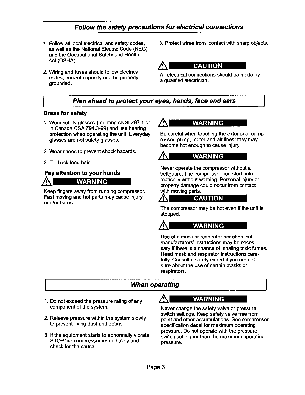
1. Follow all local electrical and safety codes,
as well as the National Electric Code (NEC)
and the Occupational Safety and Health
Act (OSHA).
3. Protect wires from contact with sharp objects.
2. Wiring and fuses should follow electrical
codes, current capacity and be properly
grounded.
All electrical connections should be made by
a qualified electrician.
Plan ahead to protect your eyes, hands, face and ears
Dress for safety
1. Wear safety glasses (meeting ANSI Z87.1 or
in Canada CSA Z94.3-99) and use hearing
protection when operating the unit. Everyday
glasses are not safety glasses.
2. Wear shoes to prevent shock hazards.
Be careful when touching the exterior of comp-
ressor, pump, motor and air lines; they may
become hot enough to cause injury.
3. 13eback long hair.
Pay attention to your hands
Keep fingers away from running compressor.
Fast moving and hot parts may cause injury
and/or bums.
Never operate the compressor without a
beltguard. The compressor can start auto-
matically without warning. Personal injury or
property damage could occur from contact
with moving parts.
The compressor may be hot even if the unit is
stopped.
Use of a mask or respirator per chemical
manufacturers' instructions may be neces-
sary if there is a chance of inhaling toxic fumes.
Read mask and respirator instructions care-
fully. Consult a safety expert if you are not
sure about the use of certain masks or
respirators.
When operating 1
1. Do not exceed the pressure rating of any
component of the system.
2. Release pressure within the system slowly
to prevent flying dust and debris.
3. If the equipment starts to abnormally vibrate,
STOP the compressor immediately and
check for the cause.
Never change the safety valve or pressure
switch settings. Keep safety valve free from
paint and other accumulations. See compressor
specification decal for maximum operating
pressure. Do not operate with the pressure
switch set higher than the maximum operating
pressure.
Page 3
Page 6

Spraying precautions
Never point a spray gun at yourself or any
other person or animal. Accidental discharge
may result in serious injury.
Reduce the risk of dangerous
environment
Extreme caution should be taken when
spraying flammable liquids as the spark from
a motor or pressure switch may cause a fire
or explosion. Ample ventilation must be
provided.
A
Spray in a well ventilated area to keep fumes
from collecting and causing serious injury and
fire hazards.
1. Do Not spray in the vicinity of open flames
or other places where a spark can cause
ignition. Do Not smoke when spraying
paint, insecticides, or other flammable
substances.
Be informed about the materials you use
.
When spraying with solvents or toxic chemi-
cals, follow the instructions provided by the
chemical manufacturer. Consult a safety
expert if unsure about the use of masks or
respirators.
.
If the material you intend to spray contains
trichloreoethane and methylene chloride, do
not use accessories that contain aluminum or
galvanized materials, as these chemicals can
react with galvanized components causing
corrosion and weakening equipment. Use
stainless steel accessories.
I Perform these maintenance operations
1. Do regular maintenance; keep all nuts, bolts,
and screws tight, to be sure equipment is in
safe working condition.
2. Inspect tank yearly for rust, pin holes or any
other imperfections that could cause it to
become unsafe.
NEVER attempt torepair or modify a tank!
Welding, drilling or any other modification will
weaken the tank resulting in damage from
rupture or explosion. Always replace worn,
cracked or damaged tanks.
,
Drain tanks of moisture after each day's use.
If unit will not be used for awhile, itis best
leave drain cock open until such time as it
is to be used. This will allow moisture to
completely drain out and help prevent
corrosion of inside of tank.
.
Always disconnect from power source before
working on or near a motor, or its connected
load. If power disconnect point is out-of-
sight, secure it in the =OFF" position and tag it
to prevent unexpected application of power.
3. Clean electrical equipment with an approved
cleaning agent, such as a dry, non-flam-
mable cleaning solvent.
Disconnect power and depressurize system
before servicing air compressor. Slightly open
drain cock after shutting off compressor.
Daily
Check oil level at sight glass.
Drain moisture from tank.
Verify the pressure switch unloader is
working by listening for a brief hissing sound
when the compressor shuts off.
Monthly
(Make sure the main power is off). Check the belts
for tension. Belts should not move up and down
when the compressor runs and when stopped,
should not have more than ½ in of play when
depressed. Be careful not to over tighten belts
during adjustment.
Remove and check air filter, replace if necessary.
V_sually check the compressor for loose parts,
excessive noise or vibration.
Change oil every 3 months or 300 hours. A
compressor grade non-detergent oil should be
used. (40 wt for K7060V/K7060HFV and 30wt
for K758OV2).
Page 4
Page 7

Find and read all warning labels found on the
air compressor.
r7i¸
Air Filter
Porous element contained within a metal or
plastic housing attached to the compressor
cylinder head which removes impurity from the
intake air of the compressor.
Air Tank
Cylindrical component which contains the
compressed air.
Check Valve
Device which prevents compressed air from
flowing back from the air tank to the compres-
sor pump.
Electric Motor
Device which provides the rotational force
necessary to operate the compressor pump.
Pressure Gauge
Device which shows the tank or regulated
pressure of the compressed air.
Pressure Switch
Device which automatically controls the on/off
cycling of the compressor. It stops the
compressor when the cut-off pressure in
the tank is reached and starts the compressor
when the air pressure drops below the cut-in
pressure.
PSI (Pounds per Square Inch)
Measurement ofthe pressure exerted by the
force of air. The actual psi is measured by a
pressure gauge on the compressor
Pump
Device which produces the compressed air
with a reciprocating piston contained within a
cylinder
Safety Valve
Device which prevents air pressure inthe air
tank from risingover a predetermined limit.
Thermal Overload Switch
Device, integrated into the electric motorwinding,
which automatically =shuts ofT'the compressor
ifthe temperature of the electric motor exceeds
a predetermined limit.
Page 5
Page 8

A
vlvl,,1:i _II_[,e
ALL ELECTRICAL WIRING SHOULD BE DONE
BY A QUALIFIED ELECTRICIAN
General Information
Adequate wiring and motor protection
should be provided for all stationary
compressors. Wiring used for other
machinery should not be used. A
qualified electrician familiar with local
electrical codes in your area should be
used.
To reduce the risk of electrical hazards, fire
hazards or damage to the compressor, use
proper circuit protection. Your compressor
is wired at the factory for operation using
the voltage shown. Connect the compressor
to a power source with the correct breaker
size.
Electrical connections must be propedy
grounded. Ground connections should be
connected at the grounding screw.
,4,
il;lll I [I] _
Overheating, short circuiting and fire damage
will result from inadequate wiring.
Incoming power should
be connected to the
posts marked (line)
Do Not Make
Connections On
Prewired Posts (Motor)!
Grounding Screw
K7060V K7580V2
K7060HFV
Voltage 230V / 1 ph 230V / 1 ph
FLA 16 23
Breaker Size 30 amp 40 amp
The motor is equipped with a manual,
resetable ovedoad device to protect itfrom
overheating. In the event the compressor will
not run and power is properly connected and
on, press the motor ovedoad reset button
located on the non drive end of the motor.
Prior to actually running the compressor,
check the following items:
Crankcase oil - Make sure the sight glass
shows ½ full or slightly above.
Make sure all rags, tools, oil, etc. are away
from the unit.
Open the air system to free itof any pressure.
Switch the compressor on for a few
revolutions to make sure the rotation is
correct. Correct rotation is clockwise
when facing the sight glass on the pump.
Operate the compressor for a few minutes
unloaded (air system open) then allow the
compressor to pump up. Make sure the
electdcal pressure switch propedy switches
off the compressor according to the setting
desired. (135 psi for K7060V/K7060HFV
and 175 psifor K7580V2)
Make sure the pressure in the tank does
not exceed its rating. Single stage comp-
ressors should operate at a maximum of
135 psi and two stage compressors should
operate at a maximum of 175 psi. If the
pressure gauge indicates a pressure that
is higher than these maximum pressures,
shut off compressor immediately and call
1-866-242-4298.
Page 6
Page 9

Low discharge pressure
Excessive noise
"knocking"
Excessive oil carryover
1. Compressor too small for
application
2. Air leaks
3. Restricted intake air
4. Blown gasket(s)
i. Broken or misaligned valves
1. Loose drive pulley or flywheel
2. Low on oil
3. Worn connecting rod or
connecting rod beadng
4. Noisy check valve
1. Worn piston rings
2. Restdcted intake air
3. Too much oil in compressor
4. Incorrect oil viscosity
1. Reduce air demand or use a compressor
with more air capacity.
2. Listen for air leaks. Apply a soap solution
to all fittings and connections. Bubbles
will form at points of leakage. 13ghten
or replace fittings or connections.
3. Clean or replace air filter.
4. Replace necessary gaskets.
5. Remove head and inspect for broken or
misaligned valves. Replace valves, if
Installa new headgasket
eachtime headisremoved
1. 13ghten ddve pulley or flywheel bolt.
2. Check for proper oil level. Low or dirty
oil may cause bearing damage.
3. Replace connecting rod and/or connecting
rod beadngs.
4. Replace check valve.
're
1. Replace with new piston dngs.
2. Clean or replace air filter.
3. Drain oil to proper oil level.
4. Use a quality non-detergent 30 or 40wt
oil specified for each model (Page 4).
Water in tank and/or 1. Normal. Amount of water will 1. Drain tank at least once per day.
discharge line increase as humidity in the 2. Add an inline filter to reduce moisture in
air increases, in the air line.
Will not run or motor 1. Low voltage
hums
2. Malfunctioning pressure switch
3. Malfunctioning check valve
1. Incorrect breaker sizeBreaker or reset
repeatedly trips
2. Low voltage
Tank does not hold
_ressure when not
running and shut off
valve is closed
3. Malfunctioning motor
4. Loose electdcal connections
5. Malfunctioning pressure switch
6. Malfunctioning check valve
1. Malfunctioning check valve
2. Loose fittings or connections
3. Crack or pin hole in tank
1. Check voltage with volt meter across both
legs of incoming power. Check reset button
on motor.
2. Repair or replace pressure switch.
3. Replace check valve or pressure switch.
1. Make sure the breaker is sized properly.
See page 6 in this manual.
2. Check voltage with volt meter across both
legs of incoming power.
3. Replace motor.
4. Check all electdcal connections.
5. Adjust or replace pressure switch.
6. Replace check valve.
ve.
Do not remove check valve
with air pressure in tank
2. "13ghtenor replace fittings or connections.
3. Replace tank. Do not attempt to repair tank.
Page 7
Page 10

Pressure switch un-
loader constantly
leaking air
Pressure switch not
unloading
Excessive vibration
Overheating
1. Malfunctioning check valve
1. Malfunctioning pressure
switch
1. Improper installation
2. Loose belts
3. Misaligned flywheel or
drive pulley
1. Compressor too small for
application
2. Cooling surfaces dirty
3. Improper cooling
1. Replace check valve if unloader bleeds
constantly.
Donot remove check valve
pressure in tank
1. Replace pressure switch if it does not release
air pressure briefly when unit shuts off.
1. Make sure unit is mounted on a level surface
with vibration pads.
2. Replace belts. Align and tighten properly.
3. Align flywheel and ddve pulley.
1. Reduce air demand or use a compressor
with more air capacity.
2. Clean all cooling surfaces of dirt and dust.
3, Install compressor in an area with adequate
cool dry air.
Page 8
Page 11

KOBALT.
Electric Compressors
..@
Illustration
Number
1
2
3
4
5
6
7
8
9
10
Model K7580V2
Shown Here as an Example
Part Description Single Stage
Compressor Pump
Air Filter
Electric Motor
Safety Valve
Pressure Switch
Tank Gauge
Tank Drain
Check Valve
Discharge Tube
Belt Guard
Drive Belts
Drive Pulley
K7060V
B3800
2281000
M182711
1400110
PSMDR21130
1400111
FIB02DC
CV21
DT0265
833500D
BA56
SAK5658
*Part Numbers Subjectto Change Without Notice
Single Stage
KTO6OHF'V
NS18S
FS008
M182711
1400110
PSMDR21130
1400111
FIB02DC
CV21
DT031
BG24163
Ba54
SAK5858
Two Slage
K7580V2
B5900
5281000
M182703
SV25200
PSMDR21KCIF
1400111
FIB02DC
CV21
DT030
BG31184
BA60
SAK51 H
Page 9
Page 12

B3800 and NS18S Single Stage Compressor Pumps
Filter for NS18S
Filter for B3800!
@
!
Page 10
Page 13

B3800 and NS18S Single Stage Compressor Pumps
ILLUSTRATION
NUMBER
01
O2
O3
04
05
06
07
08
09
10
11
12
13
13a
16
17
18
19
20
21
22
23
24
25
26
27
28
29
31
32
33
34
35
35a
36
37
38
39
4O
40a
41
PART
NUMBER
3660100
3630000
3860400
3860401
3660200
3660160
2840050
1421100
3610100
9140040
9020011
9020041
9020071
FS008
2281000
2060690
2060590
9170030
9024021
9163010
9110014
9004008
3650100
3650201
2850300
2850400
2050500
3670200
9101594
9101144
9101094
9107254
9114273
9101154
9053853
9022001
3600100
3021200
3670102
FE004
4981100
FSAD01
Gasket Kit
PART
DESCRIPTION
Crankcase
Cylinder
Head (NS18S)
Head (B3800)
Crankshaft
Crankcase Bottom
Valve Assembly
Piston
Conrod
Circlip
Step Ring
Compression Ring
Oil Ring
FilterAssembly (NS18S)
FilterAssembly (B3800)
Main Beadng Housing (NDS)
Main Beadng Housing (DS)
Main Bearing (6205)
Oil Fill Plug
Oil Seal
Flywheel Bolt
Flywheel Washer
Crankcase Bottom Gasket
Frame Gasket
Cylinder Gasket
Head Gasket
Bearing Housing Gasket
Aftercooler Gasket
Head Bolt
Aftercooler Bolt
Bearing Housing Bolt
Cylinder Bolt
Crankcase Bottom Bolt
Oil Drain Pluq
Oil Drain Tube
Oil Sight Glass
Flywheel
Wrist Pin
Aftercooler
Filter Element (NS18S)
Filter Element (B3800)
Filter Adapter
3650055
Page 11
Page 14

B5900 Two Stage Compressor Pump
Page 12
Page 15

B5900 Two Stage Compressor Pump
Illustration
Number Description Quantity Part Number
1. Crankcase 1 5961101
2. Cylinder 1 5930001
3. Head 1 5961405
4. Crankshaft 1 5961200
5. Crankcase Bottom 1 5961301
6. Valve Assembly 1 5940051
7. Conrod Insert (Half Bearing) 4 9013013
8. Conrod 2 5011101
9. Conrod Nut 4 9128234
10. HP Piston 1 5021100
11. LP Piston 1 5922100
12. HP Wrist Pin 1 5021200
13. LP Wrist Pin 1 5922200
14. Circlip 4 9140050
15. HP Step Ring 1 9020014
16. HP Compression Ring 1 9020044
17. HP Oil Ring 2 9020074
18. LP Step Ring 1 9020035
19. LP Compression Ring 1 9020047
20. LP Oil Ring 1 9020065
21. Air Filter Assembly 1 5281000
22. Air Filter Element 1 5281100
23. Bearing Housing (NDS) 1 5061690
24. Bearing Housing (DS) 1 5061590
25. Intercooler Tube 1 5962020
26. Flywheel 1 4000101
27. Main Bearing (6206) 2 9170020
28. Oil Sight Glass 1 9022003
29. Oil Fill Plug 1 9024011
30. Oil Seal 1 9163020
31. Flywheel Bolt 1 9110024
32. Flywheel Washer 1 9004009
33. Crankcase Bottom Gasket 1 5950101
34. Crankcase Gasket 1 5950201
35. Cylinder Gasket 1 5950300
36. Valve Plate Gasket 1 5940301
37. Head Gasket 1 5050400
38. Bearing Housing Gasket 2 5050500
39. Intercooler Gasket 1 5950600
40. Safety Valve (1/4 in 65 psi) 1 9049064
41. Head Bolt 6 9101756
42. Bearing Housing Bolt 8 9101144
43. Cylinder Bolt 6 9101324
44, Crankcase Btm. Bolt 12 9114262
45. Intercooler Bolt 3 9101154
46. Oil Drain Plu.q 1 9101154
46a. Oil Drain Tube 1 9053853
47. Inlet Filter Bolt 2 9101524
48. Aftercooler Gasket 1 5070200
49. Aftercooler 1 5070101
50. Safety Valve (1/4 in 217 psi) 1 9049032
Kits
Gasket Kit 53N0056 HP Ring Kit 8227093
HP Running Gear Kit 8226502 LP Ring Kit 8227092
iLP Running Gear Kit 8226503
13
Page 16

StationaryCompressorLimited Warranty
Lowes Kobalt Models K7060V, K7060HFV & K7580V2
Warranty
This warrantyof the LowesKobattStaUonarySingle.StageModelsKT060V and K7060HFV, and StationaryTwo-Stage ModalK7580V2
(hereinafterthe "KoheltProduct') extendstothe edginal userof the KobaitpreducL
Warranty Duration
This Kobait Productis warrantedtothe odginai purchaserfrom the odginaipurchasedateforthree (3) yearssubjectto the WarrantyCoverage
describedherein.
Warranty Coverage
This KobaitProductis warrantedby AbacJAmedcanIMC, Inc.USA (referredto hereinafteras "Abac'),1623 Cedar Line Drive,Rock Hill,SC
29730 to be freefiom defectsin materieland ,._3rkmanship.
This warrantyisvoidif: defects in materialsorworkmanshipordamages resultfrom mpsirsor altarationswhichhave beenmade orattempted
byothersor the unauthorizeduse of nonconformingparts;the damage isdueto normalwear, damageis dueto abuse(includingovedQading
of the KobaltProductbeyondcapacity),impropermaintenance,naglector accident;orthe damage is due to theuse of the Kobelt Product
after par_aifailureor use with improperaccessoriesorunauthedzed repairor alterattan.If KobaifModels KT060Vand K7_o0HFV are usedfor
commercialor indusb'iaipurposesthe warrantywill applyfor ninety(90) daysfrom the date of purchase.KobaltModelIO'580V2 is not limited
to a ninety (90) day warrantywhen used incommercialor indusataiappFications.
In addition this warranty _ nor indude any other Kobalt product, ind udiag:
Kobeti product sold as reconditioned or used as rental eduipmenL
Pre<lelive_y sei_ce such as assembly, oil or lubricants and adjustments.
Kobalt products that have become damaged or inoperaive because of or_nary wear, misuse (an air compressor that pumps air
more than the r_commended duty cycle during a one hour peedd may be considered misuse), cotd, heat. rain, excessive humidity.
freeze damage, use of improper lubdcanta, nagligenQe, accident, failure to operate the product in accordance with the ins_a'uchons
provided in the Owners Manual(s) supplied with the product.
Repair and Vanspurtedon costs of merchandise determined not to he _e.
Costs associated with assembly, required lubricants, adjustments or other installaifon and start-up costs.
Normal adjustments and expendable parts or accessories supplied with the product which are expected to become thoperave or
unusable after a reasonabta period of use, induding but not limited to belts, pressure switches, rubber isola_on pads, gaskets and
intake air flifers.
Products sold by Abac under the Kobaif Brand which have been manufactured by and are idenffi_ed as the product of another
company, such as electhc motors. That product manufacturer's warranty, if any, will apply.
Any component damaged in shipment or any tailure caused by installing or operaifng the comwessor under conditions not in
compliance with the installabon and operating guideiinas.
Pump or valve failure caused by rain, excessive humidity or corrosive environments and/or by using oil not specified, or by any oil
contaminalJon, or by tailure to follow proper oil maintenance guidelines.
Ring wear from inadequate tilter maintenance.
Cosme_c defects that de not inter[ere with compressor tanchonaiity.
Rusted tanks, including but not limited to rust due to improper drainage.
Electric motors and check valves after the first year of ownership.
Drain valves.
Damage due to improper _ring.
Other items not listed but considered to be general wear pads.
Warranty Performance
DURING THE ABOVE DESCRIBED WARRANTY PERIODS SHOULD YOUR KOBALTPRODUCT EXHIBIT A DEFECT IN MATERIALSOR
WORKMANSHIP, SUCH DEFECT WILL BE REPAIRED WHEN THE COMPLETE KOBALTPRODUCT ISSCHEDULED FOR REPAIRBYA
KOBALTAUTHORIZED AIR COMPRESSOR SERVICE CENTER. Servicewill he scheduledinaccordanceto the normalworkflow and
businesshoursat the servicecenterlocationand the availabtiityof replacement pade.All derisions of=Abac"withregardto this limited
warrantyshell he final.
Warranty Disclaimer
NO WARRANTY, ORALOR WRrTTEN, OTHER THAN THE ABOVE WARRANTY ISMADEWITH REGARD TO THIS KOBALT PRODUCT.
ANY IMPLIED WARRANTIES OF "ABAC"REGARDING THIS KOBALTPRODUCT INCLUDING BUT NOT LIMITEDTO, THE IMPLIED
WARRANTIES OF MERCHANTABILITY AND FITNESS FOR A pARTICULAR PURPOSE, ARE LIMITED IN DURA13ONTO THE
WARRANTY PERIODS DESCRIBED ABOVE. "ABAC"SHALL NOT BE LIABLE FOR LOSS OF USE OF THIS PRODUCT OR OTHER
INCIDENTAL OR CONSEQUENTIAL COSTS. E)_ENSES, OR DAMAGES INCURRED BY THE PURCHASER.
Limitations of Warranty Disclaimers
Some states de notallow limitationsonhowlongan impliedwarrantylasts,so the above limitationsmaynot applyto you.
Somestates do not allowthe exclusionorlimitationofincidentalorconsequentialdamages,sothe above limitationorexclusionmaynut apply
to you.
Abac/American IMC, Inc, "ABAC" Authorized Service Centers for KOBALT Product
StationaryAir Compressor sendce underthis wanantyis availableon these KobaltProductmedalsby contac_agus at 1-866-242-4298 for a
servicecenternearest youto scheduleon-site repair.
 Loading...