

ITEM/ARTICULO #234955
MODEL/MODELO #K13015F
Operator’s Manual and Parts List
Manual del Operador y Lista de las Piezas (pag. 15)
Oilless, Single Stage, Direct Drive,
Electric Air Compressor
WARNING: Read and understand all safety precautions in this manual before operating. Failure to comply with
instructions in this manual could result in personal injury, property damage, and/or voiding of your warranty.
The manufacturer WILL NOT be liable for any damage because of failure to follow these instructions.
K13015FOM_Ver.0406Printed in China

TABLE OF CONTENTS
SAFETY GUIDELINES ........................................................................................................................................................................ 3
FEATURES - Product specifications .................................................................................................................................................... 4
ELECTRICAL POWER REQUIREMENTS .......................................................................................................................................... 5
OVERVIEW .......................................................................................................................................................................................... 6
GLOSSARY OF TERMS ...................................................................................................................................................................... 6
ASSEMBLY .......................................................................................................................................................................................... 7
OPERATION ........................................................................................................................................................................................ 9
MAINTENANCE ................................................................................................................................................................................. 11
TROUBLESHOOTING CHART .......................................................................................................................................................... 11
PARTS DIAGRAM .............................................................................................................................................................................. 12
PARTS LIST ....................................................................................................................................................................................... 14
3 YEAR LIMITED WARRANTY
Nu Air Compressors and Tools S.p.A. (the Company) warrants to the original retail consumer that it will repair or replace, free of
charge, any parts found by the Company or its authorized service representatives to be defective in material or workmanship. The
warranty period will be 36 months from the date of purchase for use in consumer applications only.
This warranty covers the cost of replacement parts and labor. Transportation charges for submitting products for warranty
service, or for shipping repaired or replacement products back to the consumer, must be borne by the consumer. The effects of
corrosion, erosion and normal wear and tear are excluded from this warranty coverage. This warranty will be void if the purchaser
fails to install, maintain and operate the product in accordance with the instructions and recommendations of the Company set forth
in the owner’s manual, or if the product is used as rental equipment. The Company will not be liable for any repairs or adjustments
to the product or for any costs or labor performed by the purchaser without the Company’s prior authorization.
THE COMPANY MAKES NO OTHER WARRANTY OF ANY KIND WHATSOEVER, EXPRESS OR IMPLIED. ALL IMPLIED
WARRANTIES, INCLUDING WARRANTIES OF MERCHANTABILITY AND OF FITNESS FOR A PARTICULAR PURPOSE,
ARE HEREBY DISCLAIMED. THE WARRANTY SERVICE DESCRIBED ABOVE IS THE EXCLUSIVE REMEDY UNDER THIS
WARRANTY; LIABILITY FOR INCIDENTAL AND CONSEQUENTIAL DAMAGES IS EXCLUDED TO THE EXTENT PERMITTED
BY LAW.
Some states do not allow a disclaimer of implied warranties, or the exclusion or limitation of incidental and consequential
damages, so the above disclaimers and exclusions may not apply to you. Notwithstanding the above, any claim against the
Company under this warranty will be barred unless legal action is commenced within twelve (12) months after the warranty period
expires.
This warranty gives you specific rights, and you may have other rights that vary from state to state.
All warranty communications should be directed to the Technical Service at 1-866-242-4298.
2
K13015FOM_Ver.0406
SAFETY GUIDELINES
The following information relates to protecting YOUR SAFETY and PREVENTING EQUIPMENT PROBLEMS.
To help you recognize this information, we use the following symbols. Please read the manual and pay attention to these sections.
- A POTENTIAL HAZARD THAT WILL CAUSE SERIOUS INJURY OR LOSS OF LIFE.
DANGER:
- A POTENTIAL HAZARD THAT COULD CAUSE SERIOUS INJURY OR LOSS OF LIFE.
WARNING:
- A POTENTIAL HAZARD THAT MAY CAUSE MODERATE INJURY OR DAMAGE TO EQUIPMENT.
CAUTION:
WARNING:
1. RISK OF FIRE OR EXPLOSION. Never spray
flammable liquids in a confined area. It is normal for
the motor and pressure switch to produce sparks while
operating. If sparks come into contact with vapors from
gasoline or other solvents, they may ignite, causing
fire or explosion. Always operate the compressor in a
well-ventilated area. Do not smoke while spraying. Do
not spray where sparks or flame are present. Keep
compressor as far from spray area as possible.
2. RISK OF BURSTING. Rust can weaken the tank. Drain
the condensed water from the tank after each use to
reduce rusting. If a leak is detected in the tank, replace
the tank immediately. Do not weld, drill or modify the
air tank of this compressor. Welding or modifications
on the air compressor tank can severely impair tank
strength and cause an extremely hazardous condition.
Welding or modifying the tank in any manner will void
the warranty.
3. RISK OF ELECTRICAL SHOCK. A licensed electrician
in accordance with all local and national codes must
install all wiring. Never use an electric air compressor
outdoors when it is raining or on a wet surface, as it
may cause an electric shock.
4. RISK OF INJURY. This unit starts automatically.
ALWAYS shut off the compressor, remove the plug
from the outlet, and bleed all pressure from the system
before servicing the compressor, and when the
compressor is not in use. Do not operate the unit with
the shroud removed. Serious injury could occur from
contact with moving parts.
6. RISK OF BURNS. High temperatures are generated
by the pump and manifold. To prevent burns or other
injuries, DO NOT touch the pump, manifold or transfer
tube while the pump is running. Allow them to cool
before handling or servicing. Keep children away from
the compressor at all times.
7. RISK TO BREATHING. Do not use this air compressor
to spray chemicals. Your lungs can be damaged by
inhaling toxic fumes. A respirator may be necessary
in dusty environments or when spraying paint. Do not
carry while painting.
8. RISK OF EYE INJURY. Always wear ANSI Z87.1
approved safety goggles when using an air
compressor. Never point any nozzle or sprayer toward
a person or any part of the body. Equipment can cause
serious injury if the spray penetrates the skin.
9. RISK OF BURSTING. Do not tamper with the control
knob or adjust the relief valve for any reason. Doing
so voids all warranties. They have been preset at the
factory for the maximum pressure of this unit.
Personal injury and/or property damage may result if
the control board or the relief valve are tampered with.
10. RISK OF BURSTING. Check hoses for weak or
worn condition before each use, making certain all
connections are secure. Do not use if defect is found.
Purchase a new hose or notify an authorized service
center for examination or repair.
11. RISK TO HEARING. Always wear hearing protection
when using an air compressor. Failure to do so may
result in hearing loss.
5. RISK OF BURSTING. Check the manufacturer’s
maximum pressure rating for air tools and accessories.
Compressor outlet pressure must be regulated so as to
never exceed the maximum pressure rating of the tool.
Relieve all pressure through the hose before attaching
or removing accessories.
CAUTION:
1. Drain the moisture from the tank on a daily basis. A
clean, dry tank will help prevent corrosion.
2. Pull the pressure relief valve ring daily to ensure that
the valve is functioning properly, and to clear the valve
of any possible obstructions.
3. To provide proper ventilation for cooling, the
compressor must be kept a minimum of 12 inches (31
cm) from the nearest wall, in a well-ventilated area.
4. Fasten the compressor down securely if transporting
is necessary. Pressure must be released from the tank
before transporting.
K13015FOM_Ver.0406
12. RISK TO BREATHING. Never directly inhale the
compressed air produced by a compressor. It is not
suitable for breathing purposes.
13. The power cord on this product contains lead, a
chemical known to the State of California to cause
cancer, and birth defects or other reproductive harm.
Wash hands after handling.
5. Protect the air hose and electric cord from damage and
puncture. Inspect them weekly for weak or worn spots,
and replace if necessary.
6. To reduce the risk of electric shock, do not expose to
rain. Store indoors.
7. Never operate the compressor if the power cord or
plug are damaged. Take the equipment to the nearest
Authorized Service Center, and have a Technician
replace it.
3

FEATURES
PRODUCT SPECIFICATIONS
Running Horsepower ........................................................1.3 HP
Air Tank Capacity ............................................................ 1.5 gal.
Air Pressure ........................................................... 135 psi max.
Air Delivery ................................................. 2.4 SCFM @ 90 psi
PRESSURE
REGULATOR
KNOB
SWIVEL HANDLE
ON / OFF SWITCH
Lubrication ......................................................................Oil-Free
Adjustable Air Outlet ...................................... from 40 to 135 PSI
Gauges ...............................................................1.5 in. diameter
Input ........................................ 120 V, 60 Hz, AC only, 12 Amps
Net Weight ......................................................... 24.2 lbs. / 11 kg
Fig. A
TANK PRESSURE
GAUGE
ELECTRICAL CABLE
SHELL
AIR OUTLET
INFLATION
ADAPTER
DRAIN VALVE
INFLATION NEEDLE
INFLATION
NOZZLES
SAFETY VALVE
WHEELS
AIR CHUCK
1/4 IN. NPT MALE
CONNECTOR FITTING
1/4 IN. NPT FEMALE
CONNECTOR FITTING
QUICK COUPLER
ELECTRICAL
CABLE
SAFETY NOZZLE
BLOWER
ATTACHMENT
TIRE GAUGE
4
COIL HOSE
SEAL THREAD TAPE
K13015FOM_Ver.0406

ELECTRICAL POWER REQUIREMENTS
EXTENSION CORDS
Use only 3-wire extension cords that have 3-prong grounding
plugs and 3-pole receptacles that accept the air compressor’s plug.
When using the air compressor at a considerable distance from
the power source, use an extension cord heavy enough to carry
the current that the compressor will draw. An undersized extension
cord will cause a drop in line voltage, resulting in a loss of power
and causing the motor to overheat. Use the chart provided below
to determine the minimum wire size required in an extension cord.
Only round jacketed cords listed by Underwriter’s Laboratories (UL)
should be used.
**Ampere rating (on air compressor data plate)
0-2.0 2.1-3.4 3.5-5.0 5.1-7.0 7.1-12.0 12.1-16.0
Cord Length Wire Size (A.W.G.)
25 ft. 16 16 16 16 14 14
50 ft. 16 16 16 14 14 12
100 ft. 16 16 14 12 10 ----
**Used on 12 gauge - 20 amp circuit.
NOTE: AWG = American Wire Gauge
When working with the air compressor outdoors, use an
extension cord that is designed for outside use. This is indicated by
the letters “W-A” on the cord’s jacket.
Before using an extension cord, inspect it for loose or exposed
wires and cut or worn insulation.
GROUNDING INSTRUCTIONS
In the event of a malfunction or breakdown, grounding provides
a path of least resistance for electric current to reduce the risk of
electric shock. This air compressor is equipped with an electric cord
having an equipment-grounding conductor and a grounding plug.
The plug must be plugged into a matching outlet that is properly
installed and grounded in accordance with all local codes and
ordinances.
Do not modify the plug provided. If it will not fit the outlet,
have the proper outlet installed by a qualified electrician. Improper
connection of the equipment-grounding conductor can result in a
risk of electric shock. The conductor with insulation having an outer
surface that is green with or without yellow stripes is the equipmentgrounding conductor. If repair or replacement of the electric cord
or plug is necessary, do not connect the equipment-grounding
conductor to a live terminal.
Check with a qualified electrician or service personnel if the
grounding instructions are not completely understood, or if in doubt
as to whether the tool is properly grounded.
Repair or replace a damaged or worn cord immediately.
This air compressor is intended for use on a circuit that has an
outlet like the one shown in Figure 1. It also has a grounding pin
like the one shown.
This product must be grounded.
WARNING:
Keep the extension cord clear of the
working area. Position the cord so that it will not get caught on
lumber, tools, or other obstructions while you are working with
a power tool. Failure to do so can result in serious personal
injury.
WARNING:
Check extension cords before each use. If
damaged, replace immediately. Never use air compressor with
a damaged cord since touching the damaged area could cause
electrical shock resulting in serious injury.
NOTE: Use longer air hoses instead of long extension cords.
Your air compressor will run better and last longer.
ELECTRICAL CONNECTION
This air compressor is powered by a precision built electric
motor. It should be connected to a power supply that is 120 volts,
60 Hz, AC only (normal household current). Do not operate this
tool on direct current (DC). A substantial voltage drop will cause
a loss of power and the motor will overheat. If the air compressor
does not operate when plugged into an outlet, double check the
power supply.
SPEED AND WIRING
The no-load speed of this air compressor is approximately
26,000 rpm. This speed is not constant and decreases under a
load or with lower voltage. For voltage, the wiring in a shop is as
important as the motor’s horsepower rating. A line intended only for
lights cannot properly carry a power tool motor. Wire that is heavy
enough for a short distance will be too light for a greater distance. A
line that can support one power tool may not be able to support two
or three tools.
Fig. 1
K13015FOM_Ver.0406
5
OVERVIEW
BASIC AIR COMPRESSOR COMPONENTS
Oilless air compressors are factory lubricated for life and do
not require any oil.
The basic components of the air compressor are the electric
motor, pump, control panel and tank.
The electric motor powers the pump. The electric motor is
equipped with an overload protector and an automatic reset. If the
motor becomes overheated, the overload protector will shut it down
to prevent damage to the motor. When the motor sufficiently cools,
it will automatically restart.
The pump compresses the air and discharges it into the tank.
The tank stores the compressed air.
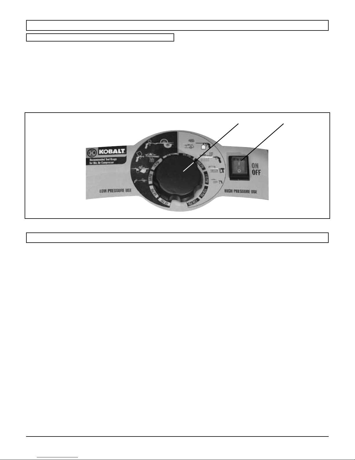
The control panel of the compressor consists of the ON/OFF
button (A) and of the pressure regulator knob (B)
As compressed air is used and the pressure level in the
tank drops to the cut-in pressure, the control board restarts the
motor automatically, without warning, and the pump resumes
compressing air. The pressure regulator shuts down the motor
when the air pressure in the tank reaches the cut-out pressure.
.
AB
GLOSSARY OF TERMS
Air Filter
Porous element contained within a metal or plastic housing
attached to the compressor cylinder head which removes
impurity from the intake air of the compressor.
Air Tank
Cylindrical component which contains the compressed air.
Check Valve
Device that prevents compressed air from flowing back from the
air tank to the compressor pump.
Cut-In Pressure
The low pressure at which the motor will automatically restart.
Cut-Off Pressure
The high pressure at which the motor will automatically shut off.
Electric Motor
Device which provides the rotational force necessary to operate
the compressor pump.
Manual On/Off Switch
Control which turns the air compressor on or off. The pressure
switch will not automatically start and control the compressor
unless the manual On/Off Switch is in the ON ( l ) position.
NPT (National Pipe Thread)
A seal thread tape must be used to provide a leak-free seal on
pipe threaded connections.
Pressure Regulator
Automatically controls the on/off cycling of the compressor.
It stops the compressor when the cut-off pressure in the tank is
reached and starts the compressor when the air pressure drops
below the cut-in pressure.
PSI (Pounds Per Square Inch)
Measurement of the pressure exerted by the force of the
air. The actual PSI is measured by a pressure gauge on the
compressor.
Pump
Produces the compressed air with a reciprocating piston
contained within the cylinder.
Safety Valve
Prevents air pressure in the air tank from rising over a
predetermined limit.
SCFM (Standard Cubic Feet Per Minute)
A unit of measure of air delivery.
Tank Pressure Gauge
Indicates the pressure in the air tank.
Thermal Overload Switch
Automatically shuts off the compressor if the temperature of the
electric motor exceeds a predetermined limit.
6
K13015FOM_Ver.0406
ASSEMBLY
FEATURES
KNOW YOUR AIR COMPRESSOR (See Fig. A, p. 4)
Before attempting to use this product, familiarize yourself with all
operating features and safety rules.
AIR OUTLET
The air outlet is located on the front of the compressor. Its pressure
is adjustable for each use from 40 to 135 psi. Pressure is adjusted
by simply rotating the knob arrow to the desired pressure setting or
use icon.
OIL-FREE UNIVERSAL MOTOR
Your air compressor features permanently lubricated bearings.
SAFETY VALVE
The safety valve is designed to automatically release air if the air
receiver pressure exceeds the preset maximum.
TANK PRESSURE GAUGE
The tank pressure gauge indicates the pressure of the air in the
tank.
ASSEMBLY
Estimated Time of Assembly: 2 minutes
Tools Required: 9/16 in., 5/8 in. and 11/16 in. wrenches
(not included)
1) UNPACKING
• Carefully remove the tool and any accessories from the
box. Make sure that all items listed in the packing list
are included.
• Inspect the tool carefully to make sure no breakage or
damage occurred during shipping.
• Do not discard the packing material until you have
carefully inspected and satisfactorily operated the tool.
• If any parts are damaged or missing, please call
1-866-242-4298 for assistance, or send a detailed FAX
request to 1-803-328-0375.
WARNING:
cause serious personal injury, always unplug the tool when
assembling parts.
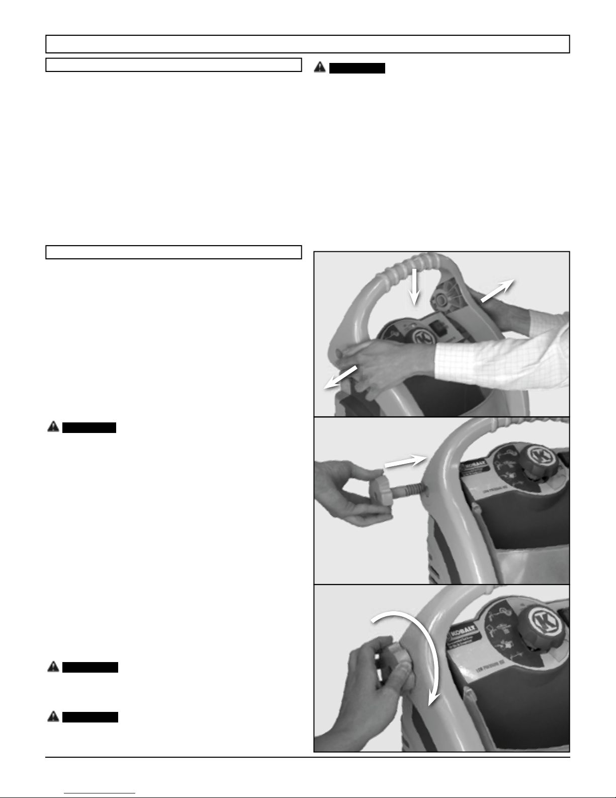
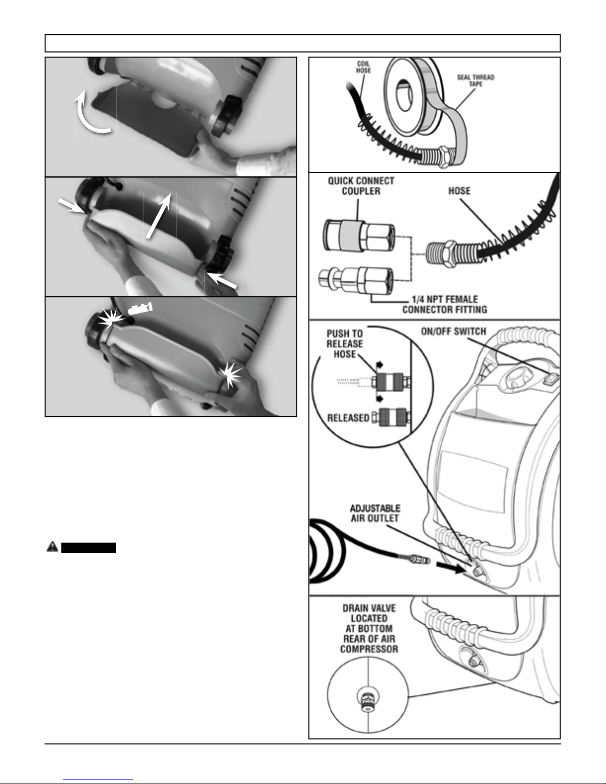
2) ASSEMBLING THE HANDLE
Slightly stretch out the handle and lower it onto the
compressor body, as shown in (Pic. 1). The handle should
line up with the guides on each side of the compressor.
Insert the two handle knobs into the holes on the sides of
the handle (Pic. 2). Tighten firmly in a clockwise direction to
secure the handle in position (Pic. 3).
3) ASSEMBLING THE ELECTRICAL CABLE SHELL
Align the 4 holes of the shell with the 4 hooks located on
the underside of the compressor (Pic. 4).
Press the sides of the shell inwards as shown in (Pic. 5).
Then push the shell forwards. The shell will click into
position when it is correctly located (Pic. 6).
To prevent accidental starting that could
Pic. 1
CAUTION:
base for an operating compressor.
Remove the compressor from the shipping pallet or carton and
place it on the floor or a hard, level surface. The compressor must
be level to ensure proper drainage of the moisture in the tank.
PACKING LIST
Air Compressor
Handle
Handle knobs (2)
Electrical cable shell
Coil Hose
Blower Attachment with Safety Nozzle
Air Chuck
Inflation Nozzles (2)
Inflation Adapter
Inflation Needle
1/4 in. NPT Quick Coupler
1/4 in. NPT Male Connector Fitting (2)
1/4 in. NPT Female Connector Fitting
Tire Gauge
Seal Thread Tape
Operator’s Manual
WARNING:
not operate this tool until the damaged or missing parts are
replaced. Failure to do so could result in possible serious
personal injury.
WARNING:
accessories not recommended for use with this tool. Any such
alteration or modification is misuse and could result in a
hazardous condition leading to possible serious personal injury.
The shipping pallet is not designed as a
If any parts are damaged or missing do
Do not attempt to modify this tool or create
Pic. 2
Pic. 3
K13015FOM_Ver.0406
7
ASSEMBLY
Pic. 4
Pic. 5
click !
Pic. 6
4) ATTACHING HOSE TO COMPRESSOR (See Fig. 7 - 9)
• Make sure the air compressor is off and unplugged.
• Apply seal thread tape to both ends of the coil hose.
• Insert one threaded end of the hose into the open end
of female connector. Hold the end of the hose with a
9/16 in. wrench and use a 5/8 in. wrench on the female
connector to tighten securely.
• Attach quick coupler to other end of the hose. Hold the
end of the hose with a 9/16 in. wrench and use a 11/16 in.
wrench on the quick coupler to tighten securely.
NOTE: Be careful not to allow threads to become
cross-threaded.
Do not attach air chuck or other tool to the
WARNING:
open end of the hose until start-up has been completed.
• Firmly grasp the open end of the hose; hold facing
away from yourself and others.
• Insert the female connector end of the coil hose into the
air outlet on the air compressor. Push the connector
firmly until you hear it click into place.
• To disconnect the hose, push the external ring nut of
the quick coupler backward.
Fig. 7
Fig. 8
Fig. 9
5) BREAKING IN THE PUMP (See Fig. 9 - 10)
• Check and tighten all bolts, fittings, etc.
• Place the switch in the OFF position and plug in the
power cord.
• Open the drain valve completely.
• Turn the air compressor ON ( l ) and run the air
compressor for 10 minutes to break in pump parts.
• Place the switch in the OFF ( O ) position.
• Close the drain valve.
8
Fig. 10
K13015FOM_Ver.0406
OPERATION
WARNING:
Do not allow familiarity with tools to make
you careless. Remember that a careless fraction of a second is
sufficient to inflict serious injury.
WARNING:
Always wear safety goggles or safety
glasses with side shields when operating power tools. Failure
to do so could result in objects being thrown into your eyes
resulting in possible serious injury.
CAUTION:
or otherwise contaminated. Using the air compressor in this
type of environment may cause damage to the unit.
Do not use in an environment that is dusty
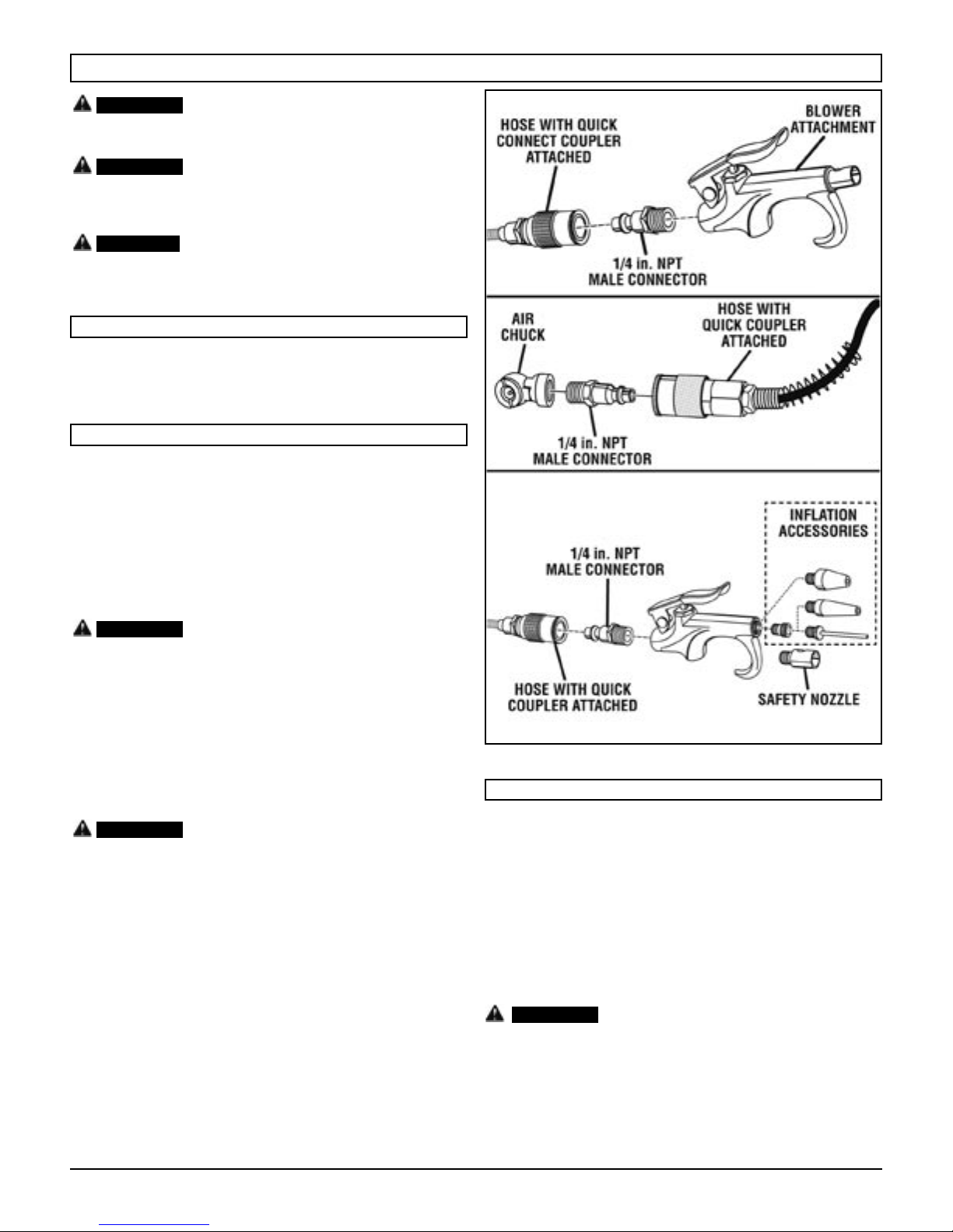
APPLICATIONS
Air compressors are utilized in a variety of air system
applications. Match hoses, connectors, air tools, and accessories to
the capabilities of the air compressor.
USING THE AIR COMPRESSOR
See Figures 9 - 13.
• Ensure power switch is in the OFF ( O ) position and air
compressor is unplugged.
• If not already installed, attach hose to compressor as
previously instructed. The hose has to be inserted into
the quick connect coupler and the regulator knob must
be rotated to select the appropriate use or pressure.
• Insert the blower attachment or connector for the tool
you wish to use into the female connector on the other
end of the spiral hose.
WARNING:
position before changing air tools or disconnecting the hose
from the air outlet. Failure to do so could result in possible
serious personal injury.
Always ensure the switch is in the OFF (O)
Fig. 11
Fig. 12
• Connect the power cord to the power supply.
• Turn the switch ON ( l ).
• Following all safety precautions in this manual and the
manufacturer’s instructions in the air tool manual, you
may now proceed to use your air-powered tool or the
blower attachment.
WARNING:
than this air compressor is capable of providing. Check the
tool manual to avoid damage to the tool or risk of personal
injury.
• When using the blower attachment, the amount of air
pressure can be further controlled by the amount the
lever of the attachment is depressed.
NOTE: Always use the minimum amount of pressure
necessary for your application. Using a higher pressure
than needed will drain air from the tank more rapidly
and cause the unit to cycle on more frequently.
• When finished, always drain the tank and unplug the
unit. Never leave the unit plugged in and/or running
unattended.
Your tool may require more air consumption
Fig. 13
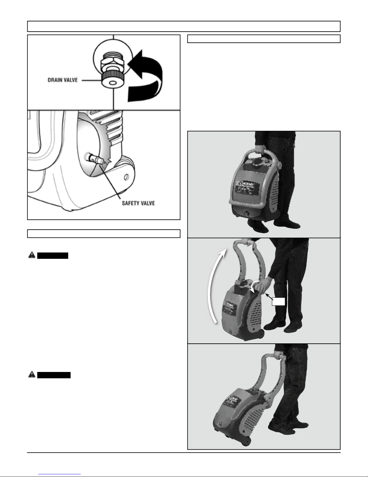
DRAINING THE TANK
See Figure 14.
To help prevent tank corrosion and keep moisture out of the air
used, the tank should be drained daily.
To drain:
• Ensure power switch is in the OFF ( O ) position and air
compressor is unplugged.
• Rotate drain valve counterclockwise (left) to open.
• Drain moisture from tank into a suitable container.
NOTE: Condensate is a polluting material and should
be disposed of in compliance with local regulations.
• If drain valve is clogged, release all air pressure,
remove and clean valve, then reinstall.
WARNING:
all air from the tank before servicing. Failure to depressurize
tank before attempting to remove valve may cause serious
personal injury.
• Rotate drain valve clockwise (right) until tightly closed.
Unplug the air compressor and release
K13015FOM_Ver.0406
9
OPERATION
Fig. 14
HOW TO USE THE SWIVEL HANDLE
The handle is designed to be used in two different positions.
• To lift up the compressor, use the handle in the ‘closed’
position (Pic. 1). Be sure the 2 handle knobs are well
tightened.
• To move the compressor using the wheels, mount the
handle in the ‘open’ position: loosen the 2 handle knobs
in counterclockwise direction (Pic. 2 - 2.1) and rotate
the handle until it reaches the highest position. At this
point re-tighten the 2 handle knobs.
The compressor can be easily trailed as shown in the
(Pic. 3).
Fig. 15
CHECKING THE SAFETY VALVE
See Figure 15.
Do not attempt to tamper with the safety
DANGER:
valve. Anything loosened from this device could fly up and
hit you. Failure to heed this warning could result in death or
serious personal injury.
The safety valve will automatically release air if the air receiver
pressure exceeds the preset maximum. The valve should be
checked before each day of use by pulling the ring by hand.
• Turn the air compressor on and allow the tank to
fill. The compressor will shut off when the pressure
reaches the preset maximum.
• Turn the air compressor off.
• Pull the ring on the safety valve to release air for three
to five seconds.
• Release the ring. Air must immediately stop escaping
when the ring is released. Any continued loss of air
after releasing the safety valve ring indicates a problem
with the safety valve. Discontinue use and seek service
before continued use of the air compressor.
WARNING:
If air leaks after the ring has been released,
or if the valve is stuck and cannot be actuated by the ring, do
not use the air compressor until the safety valve has been
replaced. Use of the air compressor in this condition could
result in serious personal injury.
Pic. 1
2.1
Pic. 2
10
Pic. 3
K13015FOM_Ver.0406

MAINTENANCE
WARNING:
replacement parts. Use of any other parts may create a hazard
or cause product damage.
WARNING:
glasses with side shields during power tool operation or when
blowing dust. If operation is dusty, also wear a dust mask.
WARNING:
from power supply, and allow unit to cool to the touch before
cleaning or making repairs on the air compressor.
Humidity in the air causes condensate to form in the air tank.
This condensate should be drained daily and/or every hour, using
the instructions found in Draining the Tank. The safety valve
automatically releases air if the air receiver pressure exceeds the
preset maximum. Check the safety valve before each use following
the instructions found in Checking the Safety Valve.
When servicing, use only identical Kobalt
Always wear safety goggles or safety
Always release all pressure, disconnect
Most plastics are susceptible to damage from various types
of commercial solvents. Do not use solvents when cleaning plastic
parts. Use clean cloths to remove dirt, dust, oil, grease, etc.
WARNING:
petroleum-based products, penetrating oils, etc., come in
contact with plastic parts. Chemicals can damage, weaken or
destroy plastic, which may result in serious personal injury.
Consequently, we do not recommended using this tool for
extended work on these types of materials. However, if you do
work with any of these materials, it is extremely important to
clean the tool using compressed air.
LUBRICATION: All of the bearings in this tool are lubricated
with a sufficient amount of high grade lubricant for the life of the unit
under normal operating conditions. Therefore, no further lubrication
of the bearings is required.
Do not at any time let brake fluids, gasoline,
TROUBLESHOOTING CHART
PROBLEM POSSIBLE CAUSE SOLUTION
1) Loss of power or overheating
2) No electrical power
3) Blown shop/house fuse
Compressor will not run
Motor hums but cannot
run or runs slowly
Fuses blow/circuit
breaker trips repeatedly
Thermal overload
protector cuts out
repeatedly
Air receiver pressure
drops when compressor
shuts off
Excessive moisture in
discharge air
Compressor runs
continuously
Compressor vibrates 1) Loose mounting bolts 1) Tighten mounting bolts
Air output lower than
normal
4) Shop/house breaker open
5) Thermal overload open
6) Pressure switch bad
7) Tank is full of air
1) Low voltage
2) Wrong gauge wire or length of extension cord
3) Shorted or open motor winding
4) Defective check valve or unloader
1) Incorrect size fuse, circuit overload
2) Wrong gauge wire or length of extension cord
3) Defective check valve or under loader
1) Low voltage
2) Lack of proper ventilation/room temperature
too high
3) Wrong gauge wire or length of extension cord
1) Loose connections (fittings, tubing, etc.)
2) Loose drain valve
1) Excessive water in air tank
2) High humidity
1) Defective pressure switch
2) Excessive air usage
1) Broken inlet valves 1) Take compressor to service center
1) Check for proper use of extension cord
2) Check to be sure unit is plugged in.
Check fuse/breaker or motor overload
3) Replace shop/house blown fuse
4) Reset shop/house breaker, determining why problem
happened
5) Motor will restart when cool
6) Take compressor to service center
7) Compressor will turn on when tank pressure drops to
cut-in pressure
1) Check with voltmeter
2) Check for proper gauge wire and cord length
3) Take compressor to service center
4) Take compressor to service center
1) Check for proper fuse, use time-delay fuse,
disconnect other electrical appliances from circuit or
operate compressor on its own branch circuit
2) Check for proper gauge wire and cord length
3) Take compressor to service center
1) Check with voltmeter
2) Move compressor to well-ventilated area
3) Check for proper gauge wire and cord length
1) Take compressor to service center
2) Tighten drain valve
Do not disassemble check valve
DANGER:
with air in tank - bleed tank.
1) Drain tank
2) Move to area of less humidity; use air line filter
1) Take compressor to service center
2) Decrease air usage; compressor not large enough
for tool’s requirement
K13015FOM_Ver.0406
11

PARTS DIAGRAM
7 4 19 5 12 11
10
8
27
26
24
31
1496 13
33 21 32 3017
343529
15
23
2
3
34
20
15
12
16
25118281522
K13015FOM_Ver.0406

PARTS DIAGRAM
72
59
58
57
56
51
50
73
54
52
61
60
55
53
64
64
63
70 6766
62
65
71
K13015FOM_Ver.0406
69
68
13

PARTS LIST
COMPRESSOR
ITEM CODE DESCRIPTION QTY
1 9413190040 TANK 1
2 9415089 PUMP OL195S 1
3 9115011 SCREW M6X16 5
4 9038274 FRONT PANEL UL 1
5 9038275 REAR PANEL UL 1
6 9038276 HANDLE 1
7 9038277 HANDLE UPPER GRIP 1
8 9038278 HANDLE LOWER GRIP 1
9 9038279 TRANSPARENT SHELL 1
10 9038280 CORD HOUSING 1
11
9038281 HANDLE KNOB 2
12 9038282 FIXING BLOCK 2
13 9038283 WHEEL 2
14 9038257 FOOT 2
15 9142572 SCREW PARKER 4,2X25 23
16 9415027 CORD 1
17 9415060 SCREW PARKER 2,9X15 2
18 9050392 DRAIN VALVE 1
19 9414765 POWER SWITCH 1
20 9038260 LOCK CABLE 1
21 9063139
22 9047061 QUICK COUPLER 1
23 9270026 RILSAN TUBE (INCHES) 16
24 9412469 ELBOW CONNECTION 1
25 9049105 SAFETY VALVE 1
26 9415024 DELIVERY PIPE 1
27 9048016 CHECK VALVE 1
28 9415023 BRACKET FOR TANK 1
29 9415025
30 9414744 PRESSURE GAUGE 50 1/4 IN. 1
31 9114280 SCREW M8X14 1
32 9053197 CONNECTION 1
33 9038286
34 9053583 ELBOW CONNECTION 2
35 9415139 AIR FILTER 1
PRESSURE SWITCH/
PRESSURE REGULATOR
BRACKET FOR PRESSURE
SWITCH
KNOB FOR PRESSURE
REGULATOR
1
1
1
PUMP
ITEM CODE DESCRIPTION QTY
50 9415090 GROUP MOTOR/CRANKCASE 1
51 A631000 CYLINDER BARREL 1
52 A610101 CONROD/PISTON 1
53 9040019 SEAL RING 1
54 9415053 CONROD COVER 1
55 9011004 SCREW TORX M5X16 1
56 A650300
57 9415091 VALVE PLATE 1
58 9415052
59 9415051 HEAD 1
60 9411131 SCREW M6X35 4
61 9122331 NUT M6 4
62 A661202 CRANKSHAFT 1
63 9170091 BEARING 1
64 9411136 BEARING 2
65 9075047 BELT 1
66 9038193 MOTOR FAN 1
67 9101055 SCREW M5X16 LEFT 1
68 9004015 WASHER SHOULDER 1
69 9411137 SEEGER 1
70 9131010 WASHER 1
71 9038190 SEMIPLASTIC COVER LOW 1
72 9038191 SEMIPLASTIC COVER HIGH 1
73 9142591 SCREW PARKER 3.9X13 4
GASKET CYLINDER-VALVE
PLATE
GASKET VALVE PLATECYLINDER HEAD
1
1
14
K13015FOM_Ver.0406

ARTICULO #234955
MODELO #K13015F
Manual del Operador y Lista de las Piezas
Sin aciete, de una sola etapa, de mando directo,
compresor de aire eléctricos
ADVERTENCIA: Lea y comprenda todas las precauciones de seguridad contenidas en este manual antes de
utilizar esta unidad. Si no cumple con las instrucciones de este manual podría ocasionar lesiones personales, daños a
la propiedad y/o la anulación de su garantía. EI fabricante NO SERÁ responsable de ningún daño por no acatar estas
instrucciones.
K13015FOM_Ver.0406
15

INDICE
PAUTAS DE SEGURIDAD ................................................................................................................................................................. 17
CARACTERÍSTICAS - Especificaciones del producto ........................................................................................................................ 18
REQUERIMIENTOS DE ALIMENTACIÓN ELÉCTRICA ..................................................................................................................... 19
RESUMEN GENERAL ....................................................................................................................................................................... 20
GLOSARIO DE TÉRMINOS ............................................................................................................................................................... 20
MONTAJE .......................................................................................................................................................................................... 21
FUNCIONAMIENTO .......................................................................................................................................................................... 23
MANTENIMIENTO .............................................................................................................................................................................. 25
SOLUCIÓN DE PROBLEMAS ........................................................................................................................................................... 26
ESQUEMA DE LAS PIEZAS ............................................................................................................................................................. 27
LISTA DE LAS PIEZAS ................................................................................................................................................................... 29
GARANTÍA LIMITADA POR 3 AÑOS
Nu Air Compressors and Tools S.p.A. (la empresa) garantiza al comprador minorista original que reparará o reemplazará en
forma gratuita todas las piezas que a juicio de la empresa o de sus representantes de servicio autorizados tengan defectos de
materiales o mano de obra. El período de garantía será de 36 meses a partir de la fecha de compra exclusivamente para el uso en
aplicaciones de consumo.
Esta garantía cubre el costo de las piezas de repuesto y la mano de obra. Los cargos de transporte correspondientes al
envío de productos para servicio de garantía o al envío al consumidor de los productos reparados o de repuesto, deberán ser
cubiertos por el consumidor. Los efectos de corrosìón, erosión, desgaste y uso normal se encuentran específicamente excluidos
de esta garantía. Esta garantía no tendrá validez si el comprador no instala, mantiene y opera el producto de conformidad con
las instrucciones y recomendaciones de la empresa, descritas en el manual de uso, o si el producto es utilizado como equipo de
alquiler. La empresa no será responsable por reparaciones o ajustes al producto, ni por costos o mano de obra, que el comprador
realice sin la autorización previa de la empresa.
LA EMPRESA NO OFRECE NINGUNA OTRA GARANTÍA, YA SEA IMPLÍCITA O EXPLÍCITA. POR LA PRESENTE
SE ANULAN TODAS LAS GARANTÍAS IMPLÍCITAS, INCLUSO TODA GARANTÍA DE COMERCIALIZACIÓN Y APTITUD
PARA UN OBJETIVO EN PARTICULAR. EL SERVICIO DE GARANTÍA PREVIAMENTE DESCRITO ES EL ÙNICO
REMEDIO OFRECIDO POR ESTA GARANTÍA; SE EXCLUYE TODA RESPONSABILIDAD POR DAÑOS INCIDENTES O
CONSECUENTES, EN LA MEDIDA QUE LO PERMITEN LAS LEYES.
En algunos estados no se permite una renuncia a las garantías implícitas o la exclusión o limitación de los daños incidentes y
consecuentes, por lo cual dichas renuncias tal vez no se apliquen en su caso. No obstante lo anterior, se prohíbe toda reclamación
contra la empresa conforme a esta garantía salvo que las acciones legales comiencen en los 12 meses siguientes a la fecha de
vencimiento del período de garantía.
Esta garantía le da las derechas específicas, y usted puede tener otras derechas que varíen de estado al estado.
Todas las comunicaciones referidas a la garantía se deberán dirigir al Servicio de Asistencia Técnica 1-866-242-4298.
16
K13015FOM_Ver.0406

PAUTAS DE SEGURIDAD
La información que sigue se refiere a la protección de SU SEGURIDAD y la PREVENCIÓN DE PROBLEMAS DEL EQUIPO. Como
ayuda para reconocer esta información, usamos los siguientes símbolos. Lea por favor el manual y preste atención a estas secciones.
- UN POSIBLE RIESGO QUE CAUSARÁ LESIONES GRAVES O LA PÉRDIDA DE LA VIDA.
PELIGRO:
- UN RIESGO POTENCIAL QUE PODRÍA PROVOCAR GRAVES LESIONES O MUERTE.
ADVERTENCIA:
- UN RIESGO POTENCIAL QUE PODRIA PROVOCAR LESIONES LEVES O DAÑAR EL EQUIPO.
PRECAUCIÓN:
ADVERTENCIA:
1. RIESGO DE INCENDIO O EXPLOSIÓN. Nunca rocíe
líquidos inflamables en un área confinada. Es normal que el
motory el interruptor de presión produzcan chispas al estar
en funcionamiento. Si las chispas entran en contacto con los
vapores de la gasolina o con otros disolventes, éstos podrían
encenderse, causando un incendio o una explosión. Siempre
opere el compresor en un lugar bien ventilado. No fume al
rociar. No rocíe donde existan chispas o Ilama. Mantenga el
compresor tan lejos del lugar de rociado como sea posible.
2. RIESGO DE EXPLOSIÓN.
tanque. Drene el agua condensada del tanque después de
cada uso para reducir la oxidación. Si detecta una fuga en el
tanque, reem plácelo inmediatamente. No suelde, no perfore
ni modifique el tanque del aire de este compresor.
La soldadura o las modificaciones en el tanque del compre-
sor de aire podrían deteriorar gravemente la resistencia del
tanque y causar una condición extremadamente peligrosa.
Soldar o modificar el tanque de cualquier manera anulará la
garantía.
3. RIESGO DE DESCARGA ELÉCTRICA.
autorizado debe hacer todas las conexiones de acuerdo con
todos los códigos elécricos nacionalesy locales. Nunca utilice
un compresor eléctrico de aire en el exterior cuando esté
Iloviendo ni lo coloque sobre una superficie mojada, ya que
esto podría causar descargas eléctricas.
4. RIESGO DE LESIONES.
automáticamente. SIEMPRE apague el compresor, quite
el enchufe del tomacorrientes, y purgue toda la presión del
sistema antes de realizar el servicio al compresor y cuando
el compresor no esté en uso. No utilice la unidad sin las
cubiertas o sin el protector de la correa ya que podría sufrir
lesiones por el contacto con las piezas móviles.
5. RIESGO DE EXPLOSIÓN. Verifique la presión nominal
máxima sugerida por el fabricante para las herramientas
y los accesorios neumáticos. La presión de salida del
compresor se debe regular de tal manera que nunca se
exceda la presión nominal máxima de la herramienta.
Antes de conectar o retirar accesorios, alivie toda presión
del tubo.
La corrosión puede debilitar el
Un electricista
Esta unidad arranca
6. RIESGO DE QUEMADURAS. La bomba y el múltiple
producen altas temperaturas. Para prevenir quemaduras u
otro tipo de heridas, NO TOQUE la bomba, el múltiple ni el
tubo de transferencia mientras la bomba se está funcionando.
Permita que se enfríe antes de manipularlos o realizar
el servicio necesario. Mantenga a los niños alejados del
compresor en todo momento.
7. RIESGO PARA LA RESPIRACIÓN. No utilice este
compresor de aire para rociar productos químicos. Pueden
resultar afectados los pulmones debido a la inhalación
de emanaciones tóxicas. Puede ser necesario utilizar un
respirador en entornos polvorientos o al rociar pintura. No
acarree la unidad mientras esté pintando.
8. RIESGO DE LESIONES OCULARES. Cuando utilice un
compresor de aire siempre use gafas de seguridad aprobadas
según ANSI Z87.1. Nunca dinja la boquilla ni el rociador hacia
una persona ni hacia alguna parte del cuerpo. EI equipo
puede causar una lesión grave si el rocio penetra en la piel.
9. RIESGO DE EXPLOSIÓN. No toque la perilla de control
ni ajuste la válvula de alivio por ninguna razón. Si lo hace
anulará la garantía. Los dos fueron preajustados de fábrica
para obtener la máxima presión en esta unidad. Alterar el
tablero de control o válvula de alivio puede producir lesiones
personales y/o daños en la propiedad.
10. RIESGO DE EXPLOSIÓN. Antes de usar la unidad revise
las mangueras para ver muestran daños o desgaste,
asegurándose de que estén seguras todas las conexiones.
No utilice la unidad si encuentra algún defecto. Adquiera una
manguera nueva o lleve la unidad a un centro de servicio
autorizado para que la examinen y reparen.
11. RIESGO AL SENTIDO DEL OÍDO. Siempre use protectores
auditivos cuando use un compresor de aire. Si no lo hace
podría sufrir pérdida de la audición.
12. RIESGO PARA LA RESPIRACIÓN. Nunca inhale
directamente el aire comprimido producido por un compresor.
No es adecuado para respirarly.
13. EI cable eléctrico en este producto contiene el plomo, un
producto químico sabido al estado de California para causar
el cáncer, y el nacimiento deserta o el otro daño reproductivo.
Manos de la colada después de dirigir.
PRECAUCIÓN:
1. Elimine la humedad del tanque todos los días. Un tanque
limpio y seco ayudará a evitar la corrosión.
2. Tire del anillo de la válvula de alivio de la presión todos los
días para asegurarse de que la válvula esté funcionando
adecuadamente y para eliminar cualquier obstrucción en la
válvula .
3. A fin de lograr una ventilación adecuada para el enfriamiento,
el compresor debe mantenerse a un minimo de 31 cm
(12 pulgadas) de la pared más cercana, en una zona bien
ventilada.
K13015FOM_Ver.0406
4. Sujete el compresor muy bien si es necesario su transporte.
Debe liberarse la presión del tanque antes de su transporte.
5. Proteja la manguera de aire y el conducto eléctrico contra
daños y pinchaduras. Inspecciónelos todas las semanas para
comprobar que no existen zonas débiles o desgastadas, y
reemplácelos si fuera necesario.
6. Para reducir el riesgo de choque eléctrico, proteja la unidad
de la Iluvia. Almacene en el interior.
7. Nunca opere el compresor si el cable de energia o el conector
están dañados. Lieve el equipo al Centro de Servicio Autorizado más cercano y pídale a un técnico que lo reemplace.
17

CARACTERÍSTICAS
ESPECIFICACIONES DEL PRODUCTO
Potencia de funcionamiento ..............................................1,3 HP
Capacidad del tanque de aire ............................... 5,3 lt (1,5 gal)
Presión de aire ....................................... 931 kPa (135 psi) máx.
Suministro de aire .......68 DCPM (2,4 PCEPM) @ 621 kPa (90 psi)
PERILLA
DEL REGULADOR
DE PRESIÓN
MANIJA
GIRATORIA
BOTÓN DE
ENCENDIDO/APAGADO
Lubricación ............................................Lubricación permanente
Toma de aire ajustable ........................................... 40 a 135 PSI
Manómetros ............................... 38 mm (1,5 pulg.) de diámetro
Corriente de entrada .............. 120 V, 60 Hz, 12 A, sólo corr. alt.
Peso neto .......................................................... 24,2 lbs. / 11 kg
Fig. A
MANÓMETRO
DEL TANQUE
CARCASA DEL
CABLE ELÉCTRICO
TOMA DE AIRE
ADAPTADOR
DE INFLADO
VÁLVULA DE
DRENAJE
AGUJA DE INFLADO
BOQUILLAS
DE INFLADO
VÁLVULA DE
SEGURIDAD
RUEDAS
CONECTOR
DE INFLADO
CONECTOR MACHO DE
6 MM (1/4 PULG.) NPT
CONECTOR HEMBRA DE
6 MM (1/4 PULG.) NPT
ACOPLADOR
RÁPIDO
CABLE
ELÉCTRICO
BOQUILLA DE
SEGURIDAD
ACCESORIO DE
SOPLADO
CALIBRE DE LAS
RUEDAS
18
MANGUERA
ESPIRAL
CINTA PARA
SELLAR ROSCAS
K13015FOM_Ver.0406

REQUERIMIENTOS DE ALIMENTACIÓN ELÉCTRICA
CORDONES DE EXTENSIÓN
Sólo utilice cordones de extensión de tres conductores con
clavijas de tres patillas y receptáculos de tres polos que acepten
la clavija del cordón del compresor. Al utilizar el compresor de
aire a una distancia considerable del suministro de corriente,
asegúrese de utilizar un cordón de extensión del grueso suficiente
para soportar el consumo de corriente del compresor. Un cordón
de extensión de un grueso insuficiente causa una caída en el
voltaje de línea, además de producir una pérdida de potencia y un
recalentamiento del motor. Básese en la tabla suministrada abajo
para determinar el calibre mínimo requerido de los conductores
del cordón de extensión. Solamente deben utilizarse cordones con
forro redondo registrados en Underwriter’s Laboratories (UL).
**Amperaje (aparece en la placa de datos del compresor)
Longitud del cordón
25 ft. 16 16 16 16 14 14
50 ft. 16 16 16 14 14 12
100 ft. 16 16 14 12 10 ----
**Se usa en los circuitos de calibre 12, de 20 A.
NOTA: AWG = Calibre conductores norma americana
0-2.0 2.1-3.4 3.5-5.0 5.1-7.0 7.1-12.0 12.1-16.0
Calibre conductores (A.W.G.)
Al trabajar a la intemperie con el compresor, utilice un cordón
de extensión fabricado para uso en el exterior. Tal característica
está indicada con las letras “W-A” en el forro del cordón.
Antes de utilizar un cordón de extensión, inspecciónelo para
ver si tiene conductores flojos o expuestos y aislamiento cortado o
gastado.
ADVERTENCIA
Mantenga el cordón de extensión
:
fuera del área de trabajo. Al trabajar con una herramienta
eléctrica, coloque el cordón de tal manera que no pueda
enredarse en la madera, herramientas o ninguna obstrucción.
La inobservancia de esta advertencia puede causar lesiones
serias.
del motor. Una línea destinada sólo para luces no puede alimentar
el motor de una herramienta eléctrica. El cable con el calibre
suficiente para una distancia corta será demsiado delgado para
una mayor distancia. Una línea que alimenta una herramienta
eléctrica quizá no sea suficiente para alimentar dos o tres
herramientas.
INSTRUCCIONES DE CONEXIÓN A TIERRA
En caso de un mal funcionamiento o desperfecto, la conexión
a tierra brinda a la corriente eléctrica una trayectoria de mínima
resistencia para disminuir el riesgo de una descarga eléctrica. Este
compresor de aire está equipado de un cordón eléctrico con una
clavija dotada de un conductor de conexión a tierra. La clavija debe
conectarse en una toma de corriente igual que esté instalada y
conectada a tierra correctamente, de conformidad con los códigos
y reglamentos de la localidad.
No modifique la clavija suministrada. Si no entra en la toma
de corriente, llame a un electricista calificado para que instale una
toma de corriente adecuada. Si se conecta de forma incorrecta el
conductor de conexión a tierra del equipo puede presentarse un
riesgo de descarga eléctrica.
El conductor con aislamiento que tiene una superficie exterior
verde con o sin tiras amarillas es el conductor de conexión a tierra
del equipo. Si es necesaria la reparación o reemplazo del cordón
eléctrico o de la clavija, no conecte el conductor de conexión a
tierra a una terminal portadora de corriente.
Consulte a un electricista calificado o técnico de servicio si no
ha comprendido completamente las instrucciones de conexión a
tierra o si no está seguro si la herramienta está conectada a tierra
correctamente.
Repare o reemplace de inmediato todo cordón dañado o
gastado.
Este compresor de aire debe utilizarse conectado a un
circuito con una toma de corriente como la mostrada en la Figura
1. También dispone de una patilla de conexión a tierra como la
mostrada. Este producto debe conectarse a tierra.
ADVERTENCIA
:
Inspeccione los cordones de extensión
cada vez antes de usarlos. Si están dañados, reemplácelos de
inmediato. Nunca utilice el compresor con un cordón dañado,
ya que si toca la parte dañada puede producirse una descarga
eléctrica, y las consecuentes lesiones serias.
NOTA: Utilice mangueras de aire largas en lugar de cordones
de extensión largos. De esta manera el compresor funciona mejor
y dura más.
CONEXIÓN ELÉCTRICA
Este compresor de aire está accionado por un motor eléctrico
fabricado con precisión. Debe conectarse únicamente a una línea
de voltaje de 120 V, 60 Hz, de corriente alterna solamente
(corriente normal para uso doméstico). No utilice esta
herramienta con corriente continua (c.c.). Una caída considerable
de voltaje causa una pérdida de potencia y el recalentamiento del
motor. Si el compresor no funciona al conectarlo en una toma de
corriente, vuelva a revisar el suministro de corriente.
VELOCIDAD Y CABLEADO
La velocidad en vacío de este compresor es 26000 rpm
aproximadamente. Esta velocidad no es constante y disminuye
durante el corte o con un voltaje bajo. En cuanto al voltaje, el
cableado de un taller es tan importante como la potencia nominal
Fig. 1
K13015FOM_Ver.0406
19

RESUMEN GENERAL
COMPONENTES BÁSICOS
DEL COMPRESOR DE AIRE
Los compresores de aire sin aceite se lubrican en fábrica para
toda su vida útil, y no requieren aceite.
Los componentes básicos del compresor de aire son el motor
eléctrico, la bomba, el panel de control
EI motor eléctrico acciona la bomba. EI motor eléctrico
está equipado con un protector contra sobrecargas y un reajuste
automático. Si el motor se sobrecalienta, el protector contra
sobrecargas lo apagará para evitar que sufra daños. Cuando el
y el tanque.
motor se enfríe lo suficiente, volverá a arrancar automáticamente.
La bomba comprime el aire y lo descarga hacia el tanque.
EI tanque almacena el aire comprimido.
El panel de control del compresor consiste en el botón de
encendido/apagado ON/OFF (A) y la perilla del regulador de
presión (B).
AI utilizar el aire comprimido y cuando el nivel de presión del
tanque baja hasta la presión de activación, el tablero de control
reinicia automáticamente el motor, sin advertencia, y la bomba
comienza a comprimir el aire. EI regulador de presión apaga el motor
cuando la presión del aire en el tanque alcanza la presión de corte.
AB
GLOSARIO DE TÉRMINOS
Bomba
Es el dispositivo que produce el aire comprimido mediante un
pistón de vaivén contenido dentro del cilindro.
Filtro de aire
Es un elemento poroso contenido dentro de un alojamiento de
metal o plástico unido al cilindro de la culata del cilindro del
compresor, el cual sirve para eliminar las impurezas del aire de
entrada del compresor.
Interruptor de encendido manual
Es el control empleado para encender y apagar el
compresor. El interruptor de presión no enciende y controla
automáticamente el compresor a menos que el interruptor de
encendido manual esté en la posición de ENCENDIDO ( l ) .
Interruptor de sobrecarga térmica
Sirve para apagar automáticamente el compresor si la
temperatura del motor eléctrico se excede de un límite
predeterminado.
Manómetro del tanque
Sirve para indicar la presión interna del tanque.
Motor eléctrico
Es el dispositivo encargado de suministrar la fuerza rotatoria
necesaria para accionar la bomba del compresor.
PCEPM (Pies cúbicos estándar por minuto)
La unidad de medida de suministro de aire.
Presión de activación
Es la presión baja a la cual arranca automáticamente el motor.
Presión de interrupción
Es la presión alta a la cual se apaga automáticamente el motor.
PSI (Libras por pulgada cuadrada)
Son las unidades de medida de la presión ejercida por la fuerza
del aire. La presión real en PSI es medida por el manómetro del
compresor.
Regulador de presión
Sirve para controlar los ciclos de encendido y apagado del
compresor. Apaga el compresor cuando se alcanza la presión
de interrupción del tanque y arranca el compresor cuando la
presión del aire desciende abajo de la presión de interrupción.
Tanque de aire
Es un componente cilíndrico que contiene el aire comprimido.
Válvula de retención
Es un dispositivo cuya función es impedir que el aire
comprimido se regrese del tanque de aire a la bomba del
compresor.
NPT (Norma Nacional de Roscado de Tubos)
Debe utilizarse una cinta selladora de roscas para tener un sello
a prueba de fugas en las conexiones roscadas de tubos.
20
Válvula de seguridad
Su función es impedir que la presión del aire ascienda más allá
de un límite predeterminado.
K13015FOM_Ver.0406

MONTAJE
CARACTERÍSTICAS
FAMILIARÍCESE CON EL COMPRESOR (Vea la Fig. A, p. 18)
Antes de intentar utilizar este producto, familiarícese con todas
las características de funcionamiento y normas de seguridad de
la unidad.
TOMA DE AIRE
La toma de aire está ubicada en la parte frontal del compresor. Se
puede ajustar la presión de 40 a 135 psi para cada uso. El ajuste
de la presión es posible simplemente rotando la flecha de la perilla
hasta el uso o la presión deseados.
MOTOR UNIVERSAL DE LUBRICACIÓN PERMANENTE
El compresor incorpora cojinetes lubricados permanentemente.
VÁLVULA DE SEGURIDAD
La válvula de seguridad está diseñada para soltar aire automáticamente si la presión del aparato receptor del aire sobrepasa el
límite máximo prefijado.
MANÓMETRO DEL TANQUE
El manómetro indica la presión del aire en el interior del tanque.
MONTAJE
Tiempo Estimado para el Montaje: 2 minutos
Equipos Necesarios: Llaves de 14, 16, 17mm (no incluidas)
1) DESEMPAQUETADO
• Extraiga cuidadosamente de la caja la herramienta y los
accesorios. Asegúrese de que estén presentes todos
los artículos enumerados en la lista de empaquetado.
• Inspeccione cuidadosamente la herramienta para
asegurarse de que no haya sufrido ninguna rotura o
daño durante el transporte.
• No deseche el material de empaquetado hasta que
haya inspeccionado cuidadosamente la herramienta y
la haya utilizado satisfactoriamente.
• Si hay piezas dañadas o faltantes, le suplicamos
llamar al 1-866-242-4298, donde le brindaremos
asistencia, o enviar un FAX al 1-803-328-0375.
la herramienta al montarle piezas a aquélla.
2) MONTAJE DE LA MANIJA
Levante levemente la manija y bájela hasta el cuerpo del
compresor, como se indica en la (Foto 1). La manija debe
quedar alineada con las guías ubicadas a cada lado del
compresor. Inserte las dos perillas de la manija en los
agujeros ubicados a los lados de ésta (Foto 2). Ajuste con
firmeza girando en la dirección de las agujas del reloj para
que la manija quede firme en su posición (Foto 3).
3) MONTAJE DE LA CARCASA DEL CABLE ELÉCTRICO
Alinee los 4 orificios de la carcasa con los 4 ganchos
ubicados en el lado inferior del compresor (Foto 4).
Presione los lados de la carcasa hacia adentro, como se
muestra en la (Foto 5). Luego empuje la carcasa hacia
adelante. Escuchará un clic cuando quede correctamente
calzada (Foto 6).
Foto 1
PRECAUCIÓN
diseñada para servir de base de un compresor en operación.
Separe el compresor de la plataforma de transportación y
colóquelo en el piso, sobre una superficie dura y nivelada. EI
compresor debe quedar nivelado para asegurar un drenaje
adecuado del agua de humedad del tanque.
LISTA DE EMPAQUETADO
- Compresor de aire
- Manija
- Perillas de la manija (2)
- Carcasa del cable eléctrico
- Manguera espiral
- Aditamento de soplado con
boquilla de seguridad
- Conector de inflado
- Boquilla de inflado (2)
- Adaptador de inflado
ADVERTENCIA
utilice esta herramienta sin haber reemplazado las piezas dañadas o faltantes. La inobservancia de esta advertencia puede
causar lesiones serias.
ADVERTENCIA
hacer accesorios no recomendados para la misma. Cualquier
alteración o modificación constituye maltrato el cual puede
causar una condición peligrosa, y como consecuencia posibles
lesiones corporales serias.
ADVERTENCIA
podría causar lesiones corporales serias, siempre desconectar
:
La plataforma de embarque no está
- Aguja de inflado
- Acoplador rápido de 6 mm
(1/4 pulg.) NPT
- Conector macho de 6 mm
(1/4 pulg.) NPT (2)
- Conector hembra de 6 mm
(1/4 pulg.) NPT
- Calibre de las ruedas
- Cinta para sellar roscas
- Manual del operador
:
Si hay piezas dañadas o faltantes, no
:
No intente modificar esta herramienta ni
:
Para evitar un arranque accidental que
Foto 2
Foto 3
K13015FOM_Ver.0406
21

MONTAJE
Foto 4
Foto 5
click !
Foto 6
4) CÓMO CONECTAR UNA MANGUERA AL COMPRESOR
(
Vea las
• Asegúrese de que esté apagado y desconectado el
• Aplique cinta para sellar roscas a ambos extremos de la
• Introduzca un extremo roscado de la manguera en el
• Conecte el acoplador rápido al otro extremo de la man-
NOTA: Tenga cuidado de no estropear las roscas.
No conecte el conector de inflado o la
otra herramienta en el extremo abierto de la manguera sin
haber efectuado el procedimiento inicial.
• Sujete firmemente el extremo abierto de la manguera,
• Introduzca el extremo del conector hembra de la
• Para desconectar la manguera, empuje hacia atrás la
Figs. 7 - 9)
compresor de aire.
manguera espiral.
extremo abierto del conector hembra. Lleve un extremo
de la manguera con una llave de 14mm y usar una llave
de 16mm para apretar firmemente el conecor hembra.
guera, sostenga éste con una llave de 14mm y usar una
llave de 17mm para apretar firmemente el acoplador rápido.
ADVERTENCIA
y sosténgalo orientado en una dirección donde no se
encuentre usted ni otras personas.
manguera espiral en la toma de aire del compresor de
aire. Empuje firmemente el conector hasta que lo oiga
hacer un chasquido al entrar en su lugar.
tuerca de anillo externo del acoplador rápido.
:
Fig. 7
Fig. 8
Fig. 9
5) USO INICIAL DE LA BOMBA (
• Revise y apriete todos los pernos, adaptadores, etc.
• Coloque el interruptor en la posición de APAGADO y
conecte el cordón de corriente.
• Abra completamente la válvula de drenaje.
• ENCIENDA el compresor, posición (l), y déjelo funcionar
10 minutos para dar a las piezas de la bomba un uso inicial.
• Ponga el interruptor en la posición de APAGADO (O).
• Cierre la válvula de drenaje.
22
Vea las
Figs. 9 - 10)
Fig. 10
K13015FOM_Ver.0406

FUNCIONAMIENTO
No permita que su familarización con
ADVERTENCIA:
las herramientas lo vuelva descuidado. Tenga presente que
un descuido de un instante es suficiente para causar una
lesión grave.
Cuando utilice herramientas eléctricas,
ADVERTENCIA:
póngase siempre gafas de seguridad o anteojos protectores
con protección lateral. La inobservancia de esta advertencia
puede causar el lanzamiento de objetos a los ojos, y por
consecuencia posibles lesiones serias.
PRECAUCIÓN:
polvoriento o contaminado de cualquier forma. Si se utiliza el
compresor de aire en este tipo de entorno puede dañarse.
Los compresores de aire se utilizan en una variedad de usos
de sistemas de suministro de aire. Las mangueras, conectores,
herramientas de aire y accesorios deben corresponder a la
capacidad del compresor de aire.
USO DEL COMPRESOR DE AIRE
Vea las Figuras 9 a 13.
• Asegúrese de que el interruptor de corriente esté en
la posición de APAGADO (O) y el compresor esté
desconectado.
• Si no está instalada aún la manguera, conéctela al
compresor como se indicó anteriormente. La manguera
debe insertarse en el acoplador de conexión rápida y
la perilla del regulador debe girarse hasta la marca del
uso o la presión apropiado.
• Introduzca el aditamento de soplado o el conector de
la herramienta de aire deseada en el conector hembra
situado en el otro lado de la manguera espiral.
No utilice la unidad en ningún entorno
APLICACIONES
Fig. 11
Fig. 12
ADVERTENCIA:
ruptor esté en la posición de APAGADO (O) antes de cambiar
de herramienta de aire o desconectar la manguera de la
salidad de aire. La inobser-vancia de esta advertencia puede
causar lesiones serias.
• Conecte el cordón al suministro de corriente.
• Ponga el interruptor en la posición de ENCENDIDO (l).
• Ahora puede proceder a utilizar la herramienta
accionada por aire deseada o el aditamento de
soplado, siguiendo las medidas de precaución
indicadas en este manual y las instrucciones del
fabricante de la herramienta de aire señaladas en el
manual de la herramienta correspondiente.
ADVERTENCIA:
necesitar más aire del que este compresor es capaz de
suministrar. Estudie el manual de la herramienta para evitar
dañarla y sufrir un riesgo de lesiones.
• Al utilizar el aditamento de soplado, la cantidad de
presión de aire puede controlarse adicionalmente
mediante el grado de presión aplicado con la mano en
la palanca de dicho aditamento.
NOTA: Siempre use la cantidad de presión mínima
necesaria en cada caso. Si usa una presión mayor
de la necesaria se drena el aire del tanque con mayor
rapidez y la unidad efectúa con mayor frecuencia su
ciclo de funcionamiento.
• Al terminar, siempre drene el tanque y desconecte
la unidad. Nunca deje conectada ni funcionando
desatendida la unidad.
Siempre asegúrese de que el inter-
Una herramienta determinada puede
Fig. 13
DRENADO DEL TANQUE
Vea la Figura 14.
Como ayuda para impedir la corrosión del tanque y mantener
el aire libre de humedad, debe drenarse diariamente el tanque de
aire.
Para drenar el tanque:
• Asegúrese de que el interruptor de corriente esté en
la posición de APAGADO (O) y el compresor esté
desconectado.
• Gire a la izquierda la válvula de drenaje para abrirla.
• Drene la humedad del tanque, recibiéndola en un
recipiente adecuado.
NOTA: La humedad condensada es material
contaminante y debe desecharse de conformidad con
los reglamentos locales.
• Si se tapa la válvula de drenaje, purgue toda la presión
de aire, retire la válvula, límpiela y vuelva a instalarla.
ADVERTENCIA:
suelte todo el aire del tanque antes de prestar servicio a la
unidad. Si no se purga la presión del tanque antes de intentar
retirar la válvula, pueden producirse lesiones serias.
• Gire a la derecha la válvula de drenaje hasta dejarla
firmemente cerrada.
Desconecte el compresor de aire y
K13015FOM_Ver.0406
23

FUNCIONAMIENTO
La manija está diseñada para usarse en dos posiciones
diferentes.
• Para levantar el compresor, coloque la manija en la
posición ‘cerrada’ (Foto 1). Asegúrese de que las 2
perillas de la manija estén bien apretadas.
• Para desplazar el compresor usando las ruedas,
coloque la manija en la posición ‘abierta’: afloje las 2
perillas de la manija girándolas en el sentido contrario
al de las agujas del reloj (Foto 2 - 2.1) y gire la manija
Fig. 14
hasta que llegue a la posición más alta y una vez
logrado esto, vuelva a ajustar las 2 perillas.
El compresor puede arrastrarse fácilmente como se
muestra en la (Foto 3
CÓMO USAR LA MANIJA GIRATORIA
).
Fig. 15
REVISIÓN DE LA VÁLVULA DE SEGURIDAD
Vea la Figura 15.
No intente forzar o alterar la válvula de segu-
PELIGRO:
ridad. Cualquier pieza floja de este dispositivo puede volar y
golpearlo. La inobservancia de esta advertencia podría causar
lesiones serias e incluso la muerte.
La válvula de seguridad está diseñada para soltar aire
automáticamente si la presión del aparato receptor del aire
sobrepasa el límite máximo prefijado. Debe revisarse la válvula
cada día antes de usar la unidad; para ello, tire del aro con la mano.
• Encienda el compresor y permita que se llene el
tanque. El compresor se apaga cuando la presión
alcanza el límite máximo prefijado.
• Apague el compresor.
• Tire del aro de la válvula de seguridad para soltar aire
durante tres o cinco segundos.
• Suelte el aro. Al soltar el aro, el aire debe dejar de
salir de inmediato. Cualquier pérdida de aire que
permanezca después de soltarse el aro de la válvula
de seguridad indica un problema en ésta. Interrumpa
el uso de la unidad y permita que se dé servicio a la
misma antes de volver a usar el compresor.
Foto 1
2.1
Foto 2
ADVERTENCIA:
Si se fuga aire después de soltar el aro,
o si está pegada la válvula y no puede accionarse con el aro,
no utilice el compresor de aire, sino hasta haber reemplazado
la válvula. Utilizar el compresor de aire en estas condiciones
puede producir lesiones serias.
24
Foto 3
K13015FOM_Ver.0406

MANTENIMIENTO
Al dar servicio a la unidad, sólo utilice
ADVERTENCIA
piezas de repuesto Kobalt idénticas. El empleo de piezas
diferentes puede causar un peligro o dañar el producto.
ADVERTENCIA
o anteojos protectores con protección lateral al usar
herramientas eléctricas o al soplar el polvo con aire
comprimido. Si la operación genera mucho polvo, también
póngase una mascarilla contra el polvo.
ADVERTENCIA
desconecte la unidad del suministro de corriente y permita
que se enfríe antes de limpiarla o efectuarle reparaciones.
La humedad del aire causa se condensa en el tanque. Esta
humedad condensada debe drenarse diariamente y/o cada
hora siguiendo las instrucciones encontradas en el apartado
Drenado del tanque. La válvula de seguridad está diseñada para
soltar aire automáticamente si la presión del aparato receptor
del aire sobrepasa el límite máximo prefijado. Revise la válvula
de seguridad cada vez antes de usar la unidad siguiendo las
instrucciones indicadas en el apartado Revisión de la válvula de
seguridad
.
:
Siempre use gafas de seguridad
:
Siempre purgue toda la presión,
:
La mayoría de los plásticos son susceptibles a diferentes tipos
de solventes comerciales. Evite el empleo de solventes al limpiar
piezas de plástico. Utilice paños limpios para eliminar la suciedad,
el polvo, el aceite, la grasa, etc.
ADVERTENCIA
No permita en ningún momento que
:
fluidos para frenos, gasolina, productos a base de petróleo,
aceites penetrantes, etc., lleguen a tocar las piezas de
plástico. Las sustancias químicas pueden dañar, debilitar o
destruir el plástico, lo cual a su vez puede producir lesiones
corporales serias. Por consiguiente, no recomendamos el uso
de esta herramienta durante períodos prolongados de trabajo
en estos tipos de materiales. Sin embargo, si usted trabaja
con cualquiera de estos materiales, es sumamente importante
limpiar la herramienta con aire comprimido.
LUBRICACIÓN: Todos los cojinetes de esta herramienta
están lubricados con suficiente cantidad de aceite de alta calidad
para toda la vida útil de la unidad en condiciones normales de
funcionamiento. Por lo tanto, no se necesita lubricación adicional
de los cojinetes.
K13015FOM_Ver.0406
25

SOLUCIÓN DE PROBLEMAS
PROBLEMA CAUSA SOLUCIÓN
1) Recalentamiento o pérdida de potencia
2) No hay corriente eléctrica
El compresor no
arranca
El motor zumba pero
no funciona o lo hace
con lentitud
Los fusibles
se funden o el
disyuntor del
circuito se dispara
continuamente
El protector
contra sobrecarga
térmica interrumpe
la corriente
continuamente
La presión del
aparato receptor
del aire desciende
cuando se apaga el
compresor
Humedad excesiva
en el aire de descarga
El compresor
funciona
continuamente
El compresor vibra 1) Afloje los pernos de montaje 1) Apriete los pernos de montaje
Producción de aire
más baja de lo normal
3) Fusible fundido en el taller o casa
4) Disyuntor abierto en el taller o casa
5) Protector sobrecarga térmica activado
6) Interruptor de presión defectuoso
7) Tanque lleno de aire
1) Voltaje bajo
2) Cordón de extensión de calibre o
longitud equivocados
3) El devanado del motor tiene corto o
está abierto
4) Válvula de retención o de seguridad
defectuosa
1) Fusible de capacidad incorrecta,
sobrecarga en el circuito
2) Cordón de extensión de calibre o
longitud equivocados
3) Válvula de retención o de seguridad
defectuosa
1) Voltaje bajo
2) Ventilación insuficiente/temperatura
ambiental demasiado elevada
3) Cordón de extensión de calibre o
longitud equivocados
1) Conexiones flojas (adaptadores,
mangueras, etc.)
2) Válvula de drenaje floja
1) Cantidad excesiva de agua en el
tanque de aire
2) Alta humedad
1) Interruptor de presión defectuoso
2) Uso excesivo de aire
1) Válvulas de entrada descompuestas 1) Lleve el compresor a un centro de servicio
1) Verifique que el cordón de extensión esté usándose de forma
correcta.
2) Revise para asegurarse de que esté conectada la unidad.
Revise fusible, disyuntor o protector contra sobrecarga térmica
3) Reemplace el fusible fundido del taller o casa
4) Restablezca el disyuntor del taller o casa, y determine la
causa del problema
5) El motor vuelve a arrancar al enfriarse
6) Lleve el compresor a un centro de servicio
7) El compresor se enciende cuando la presión del tanque
desciende a la presión de activación
1) Revisar con voltímetro
2) Verifique que el calibre y la longitud del cable sean los
correctos
3) Lleve el compresor a un centro de servicio
4) Lleve el compresor a un centro de servicio
1) Verifique que el fusible sea de la capacidad correcta, use
un fusible con retardo de tiempo, desconecte otros aparatos
eléctricos del circuito o conecte el compresor a un subcircuito
exclusivo
2) Verifique que el calibre y la longitud del cable sean los
correctos
3) Lleve el compresor a un centro de servicio
1) Revise con voltímetro
2) Lleve el compresor a un lugar bien ventilado
3) Verifique que el calibre y la longitud del cable sean los
correctos
1) Lleve el compresor a un centro de servicio
2) Apriete la válvula de drenaje
PELIGRO:
No desmonte la válvula de retención
teniendo aire en el tanque; vacíe el tanque.
1) Drene el tanque
2) Lleve la unidad a un lugar de menor humedad; use un filtro
de aire en línea
1) Lleve el compresor a un centro de servicio
2) Disminuya el consumo de aire; el compresor no es de la
suficiente capacidad para las necesidades de la herramienta
26
K13015FOM_Ver.0406

ESQUEMA DE LAS PIEZAS
7 4 19 5 12 11
10
8
27
26
24
31
1496 13
33 21 32 3017
343529
15
23
2
3
34
20
15
K13015FOM_Ver.0406
16
25118281522
27

ESQUEMA DE LAS PIEZAS
72
59
58
57
56
51
50
73
54
52
61
60
55
53
64
64
63
70 6766
62
65
71
28
69
68
K13015FOM_Ver.0406

LISTA DE LAS PIEZAS
COMPRESOR
ART CODE DESCRIPCIÓN CANT
1 9413190040 DEPÓSITO 1
2 9415089 BOMBA OL195S 1
3 9115011 TORNILLO M6X16 5
4 9038274 PANEL FRONTAL UL 1
5 9038275 PANEL POSTERIOR AZUR UL 1
6 9038276 MANIJA 1
7 9038277
8 9038278
9 9038279 CÁSCARA TRANSPARENTE 1
10 9038280 CARCASA DEL CORDÓN 1
11
9038281 PERILLAS DE LA MANIJA 2
12 9038282 TERRAJA 2
13 9038283 RUEDA 2
14 9038257 PIE 2
15 9142572 TORNILLO PARKER 4,2X25 23
16 9415027 CORDÓN 1
17 9415060 TORNILLO PARKER 2,9X15 2
18 9050392 VÁLVULA DE DRENAJE 1
19 9414765
20 9038260 CERRADURA DEL CORDÓN 1
21 9063139
22 9047061 ACOPLADOR RÁPIDO 1
23 9270026 TUBO RILSAN (METROS) 0,4
24 9412469 CONEXIÓN ANGULAR 1
25 9049105 VÁLVULA DE SEGURIDAD 1
26 9415024 TUBO COLECTOR SALIDA 1
27 9048016 VÁLVULA DE CONTROL 1
28 9415023 SOPORTE DEL DEPÓSITO 1
29 9415025
30 9414744 MANÓMETRO 50 1/4 PULG. 1
31 9114280 TORNILLO M8X14 1
32 9053197 CONEXIÓN 1
33 9038286
34 9053583 CONEXIÓN ANGULAR 2
35 9415139 FILTRO DE AIRE 1
APRETÓN SUPERIOR DE LA
MANIJA
APRETÓN INFERIOR DE LA
MANIJA
BOTÓN DE ENCENDIDO/
APAGADO
INTERRUPTOR DE
PRESIÓN/REGULADOR DE
PRESIÓN
SOPORTE DEL
INTERRUPTOR DE PRESIÓN
PERILLA DEL REGULADOR
DE PRESIÓN
1
1
1
1
1
1
BOMBA
ART CODE DESCRIPCIÓN CANT
50 9415090 CÁRTER 1
51 A631000 CILINDRO MECA 1
52 A610101 BIELA 1
53 9040019 TORICA 1
54 9415053 TAPÓN BIELA 1
55 9011004 TORNILLO TORX M5X16 1
56 A650300
57 9415091 PLACA VÁLVULA 1
58 9415052
59 9415051 CABEZAL 1
60 9411131 TORNILLO M6X35 4
61 9122331 TUERCA M6 4
62 A661202 CIGÜEÑAL 1
63 9170091 RODAMIENTO 1
64 9411136 RODAMIENTO 2
65 9075047 CORREA 1
66 9038193 VENTILADOR DEL MOTOR 1
67 9101055 TORNILLO M5X16 IZQUIERDO 1
68 9004015 ARANDELA SEPARADOR 1
69 9411137 SEGUER 1
70 9131010 ARANDELA 1
71 9038190
72 9038191 CUBIERTA SEMI PLÁSTICA ALTA 1
73 9142591 TORNILLO PARKER 3.9X13 4
JUNTA CILINDRO - PLACA
VÁLVULA
JUNTA PLACA VÁLVULA CULATA CILINDRO
CUBIERTA SEMI PLÁSTICA
BAJA
1
1
1
K13015FOM_Ver.0406
29

30
K13015FOM_Ver.0406

K13015FOM_Ver.0406
31

9415147
 Loading...