

Page 1

1
Serial Number Purchase Date
Questions, problems, missing parts? Before returning to your retailer, call our
customer service department at 1-888-3KOBALT (1-888-356-2258), 8 a.m - 8 p.m., EST,
Monday - Friday.
ATTACH YOUR RECEIPT HERE
ITEM #0595496
MODEL #0056643
1-DRAWER,
2-DOOR
CABINET
Français p. 15
Español p. 29
AB15134
Lowes.com
KOBALT® and the K Design® are registered
trademarks of LF, LLC. All Rights Reserved.
Page 2

TABLE OF CONTENTS
2
Lowes.com
Package Contents....................................................................................................................3
Hardware Contents...................................................................................................................4
Safety Information ....................................................................................................................4
Preparation .............................................................................................................................4
Assembly Instructions ............................................................................................................5
Troubleshooting ......................................................................................................................14
Warranty .................................................................................................................................14
Replacement Parts List ...........................................................................................................14
Page 3
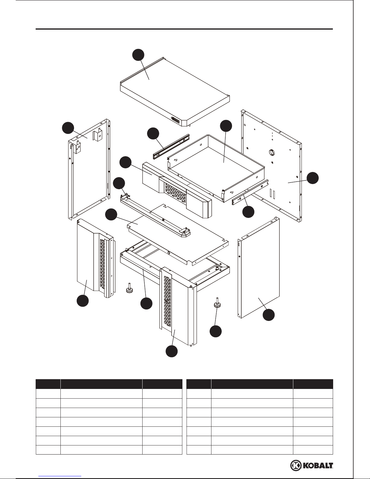
PACKAGE CONTENTS
PART QUANTITY
A
B
C
D
E
F
G
1
1
1
1
1
1
1
1
1
4
1
1
2
2
Back
Left side
Right side
Top
Base
Bottom shelf
Cabinet divider
DESCRIPTION PART QUANTITY
H
I
J
K
L
M
N
Left door
Right door
Leg leveler assembly
Drawer front
Drawer
Outside slide (preassembled)
Inside slide (preassembled)
DESCRIPTION
3
Lowes.com
C
D
A
B
E
I
H
J
L
M
N
K
G
F
Page 4
SAFETY INFORMATION
PREPARATION
Before beginning assembly of product, make sure all parts are present. Compare parts with
package contents list and hardware contents above. If any part is missing or damaged, do not
attempt to
It is recommended that this product be assembled on a clean, soft surface, such as a piece of
cardboard.
assemble the product. Contact customer service for replacement parts.
Estimated Assembly Time: 1 hour (does not include unpacking time)
Tools Required for Assembly (not included):
Drill, Phillips screwdriver,
Adjustable wrench
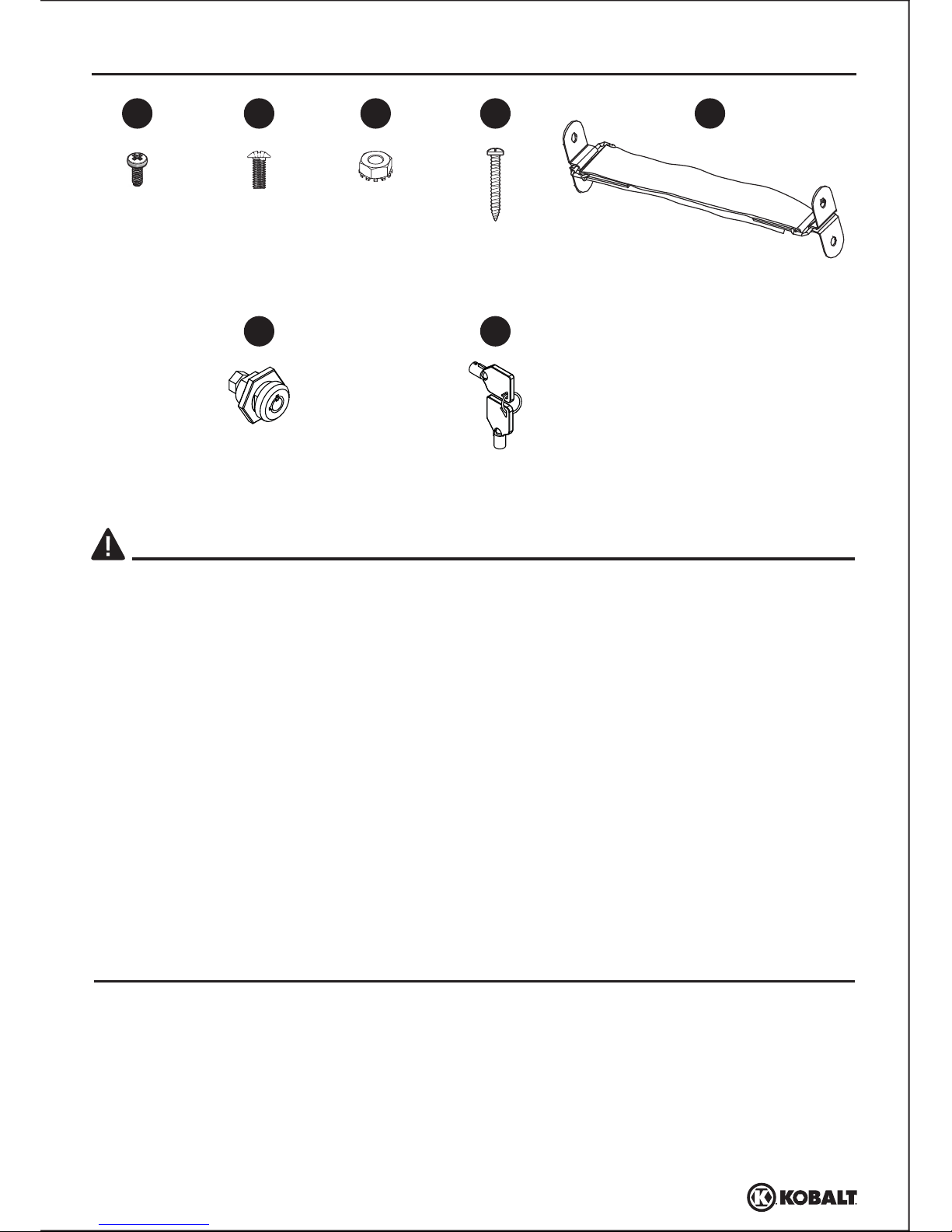
ST4.8 x 10 mm
Screw
Qty. 14 + 2
ST4 x 20 mm
Screw
Qty. 2
Wall strap
Qty. 1
Lock
(preassembled to right door (I))
Qty. 1
Key
(preassembled to right door (I))
Qty. 2
AA
BB
CC
DD
EE
FF
#8-32 Nut
Qty. 2
#8-32 x 3/8 in.
Bolt
Qty. 2
CAUTION
• Do not overload shelf (100 lbs. max.) or store loose or heavy items on the top of the unit.
• When storing items on the bottom shelf, equally distribute loads.
• Do not store flammable liquids in the unit unless they are secured in an approved container.
• Do not store gasoline in the unit under any circumstances.
• When mounting unit to wall, ensure studs are plumb and square.
• When mounting multiple units to a wall, check local building codes or consult with a contractor to
determine the maximum load rating for your desired installation.
WARNING
• Do not stand on, step on, or alter this unit for anything outside the designed function of storage.
• Use care when handling and assembling metal plates.
• The metal may have sharp edges or corners. The use of protective gloves is recommended.
• Always remember to use proper lifting techniques when moving the boxed or assembled unit.
GG
HARDWARE CONTENTS (shown actual size)
4
Lowes.com
Page 5
ASSEMBLY INSTRUCTIONS
1
B
B
C
A
A
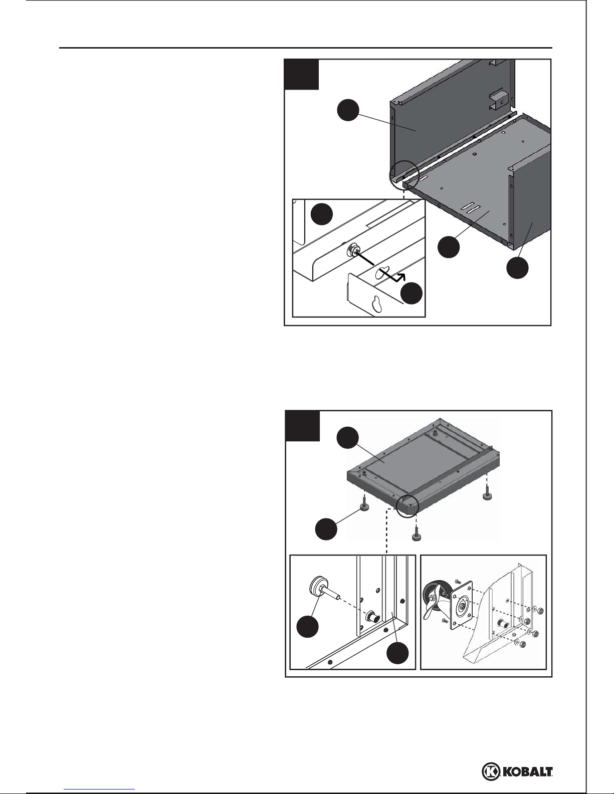
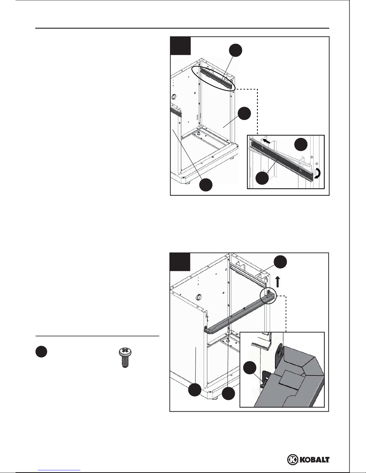
1.
Slide preassembled screws into key slots
of back (A) to connect left side (B) and
right side (C) to back (A). Tighten the
screws.
Note: Be sure to keep back (A) on a soft
surface, such as carpeting or a piece of
cardboard, to protect it from scratches.
Note: Ensure all four legs are level before
moving on to the next step.
2
J
E
2.
Screw leg leveler assemblies (J) to base
(E) until tight.
OPTIONAL
To move the unit freely, you can install
Casters (Item #0112281, sold separately)
in place of the leg leveler assemblies (J).
Simply install swivel casters onto base (E)
using head bolts, steel nuts, and locking
washers provided with the separate
purchase.
J
E
OPTIONAL
5
Lowes.com
Page 6
L
ASSEMBLY INSTRUCTIONS
Hardware Used
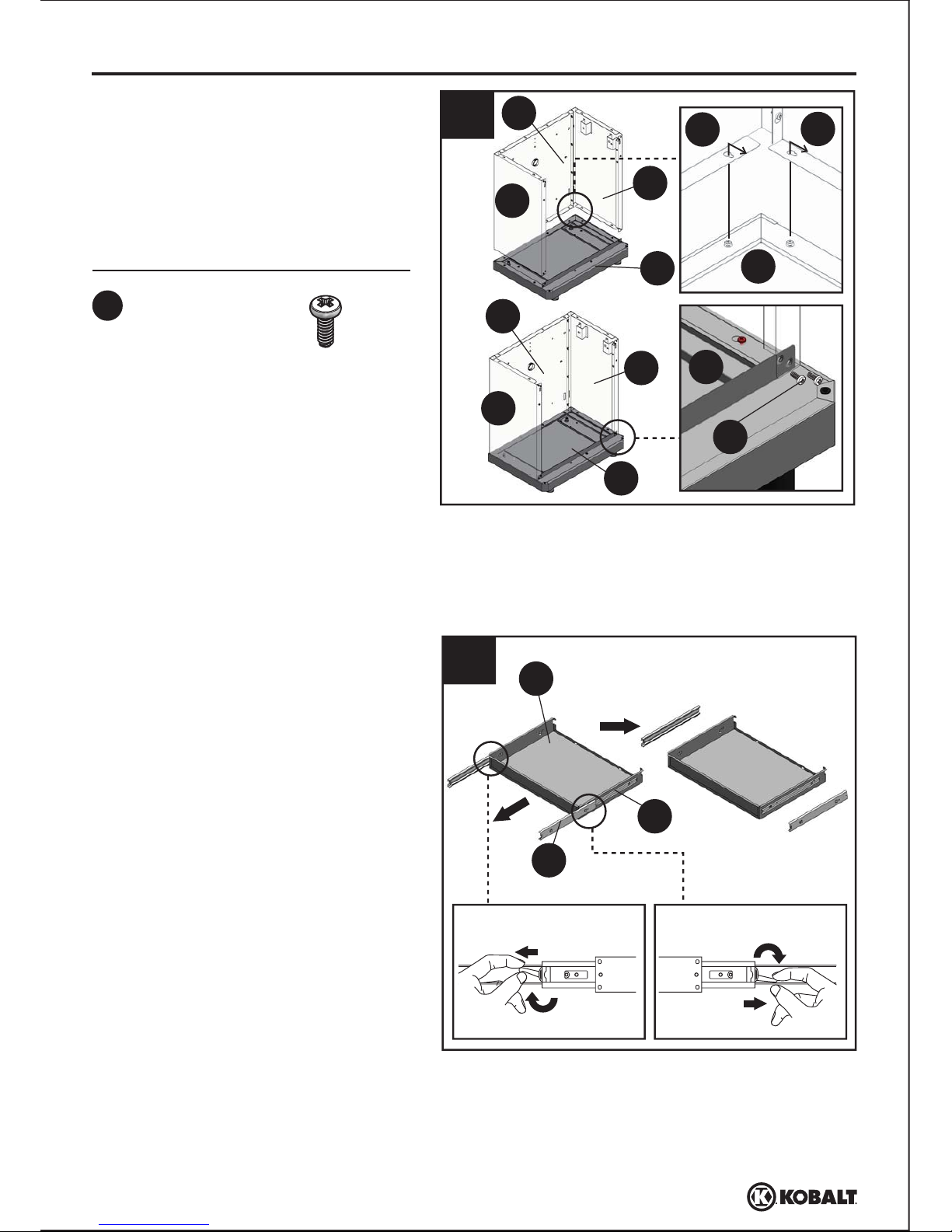
4
AA
x 4ST4.8 x 10 mm
Screw
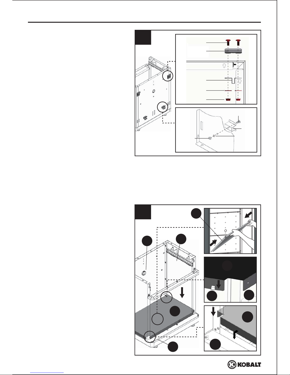
3.
Push and tighten the preassembled
screws on the assembled unit from Step
1 to the key slots of base (E). Tighten the
ST4.8 x 10 mm screws (AA) to the front
edge of the base (E) to connect left side
(B) and right side (C) to base (E).
4. Flick the plastic clips on the inside
slide (N) to detach the outside slide
(M) from the inside slide (N). For the
plastic clip on the left side, please
press down and slide outside slide
(M) off inside slide (N). For the
plastic clip on the right side, please
push up and slide outside slide (M)
off inside slide (N).
Left sideRight side
M
N
6
Lowes.com
AA
3
C
A
E
E
E
B
B
C
A
C
A
E
Page 7
ASSEMBLY INSTRUCTIONS
Hardware Used
5
6
G
C
B
AA
AA
x 2ST4.8 x 10 mm
Screw
M
C
C
M
B
5.
Insert the back tongue of outside slide
(M) to the back slot on right side (C),
then assemble the front tongue of
outside slide (M) to the front slot on
right side (C).
Repeat above step for left side (B).
6.
Push key slot in the bottom of cabinet
divider (G) to the preassembled screws
on the left side (B) and right side (C).
Tighten the screws. Screw two ST4.8 x
10 mm screws (AA) to the two top holes
of cabinet divider (G) to connect cabinet
divider (G) to left side (B) and right side
(C).
Note: Make sure the right outside slide (M
)
is assembled on right side (C)and left
outside slide (M)on the left side (B).
7
Lowes.com
Page 8
F
E
ASSEMBLY INSTRUCTIONS
8
E
C
A
A
C
F
F
F
8.
Install the bottom shelf (F) by tipping it
to the side and inserting it into the
cabinet. With bottom shelf (F) at an
angle, align the cut-outs on the
bottom shelf (F) with the back seams
caused by left side (B), right side (C),
and back (A). Carefully lower the
bottom shelf (F), ensuring the front of
the bottom shelf (F) goes over the
front flange of the base (E).
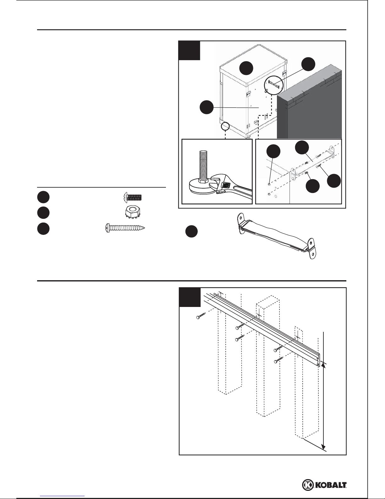
7
Carriage bolts
Truss HD screws
Outside cabinet
brackets
Inside cabinet
brackets
Flat washers
Flat washers
Flange nuts
Hex nuts
Cabinet
spacers
7.
OPTIONAL
If you plan to hang the unit on the wall
using the K-Rail
®
(Item #0103683, sold
separately) and Wall Mount Kit (Item
#0345926, sold separately), please
follow the below step. Otherwise,
proceed to Step 8. Attach carriage bolts,
flange nuts, flat washers, outside
cabinet brackets and inside cabinet
brackets to the back of the assembled
unit. Screw cabinet spacer with truss
HD screws, flat washers and hex nuts to
the back of the assembled unit.
Note: If inside front shelf tabs are
flattened during assembly, use a flat
screwdriver (not included) to adjust tabs.
8
Lowes.com
Page 9
L
K
ASSEMBLY INSTRUCTIONS
10
Hardware Used
AA
x 4ST4.8 x 10 mm
Screw
Hardware Used
AA
x 2ST4.8 x 10 mm
Screw
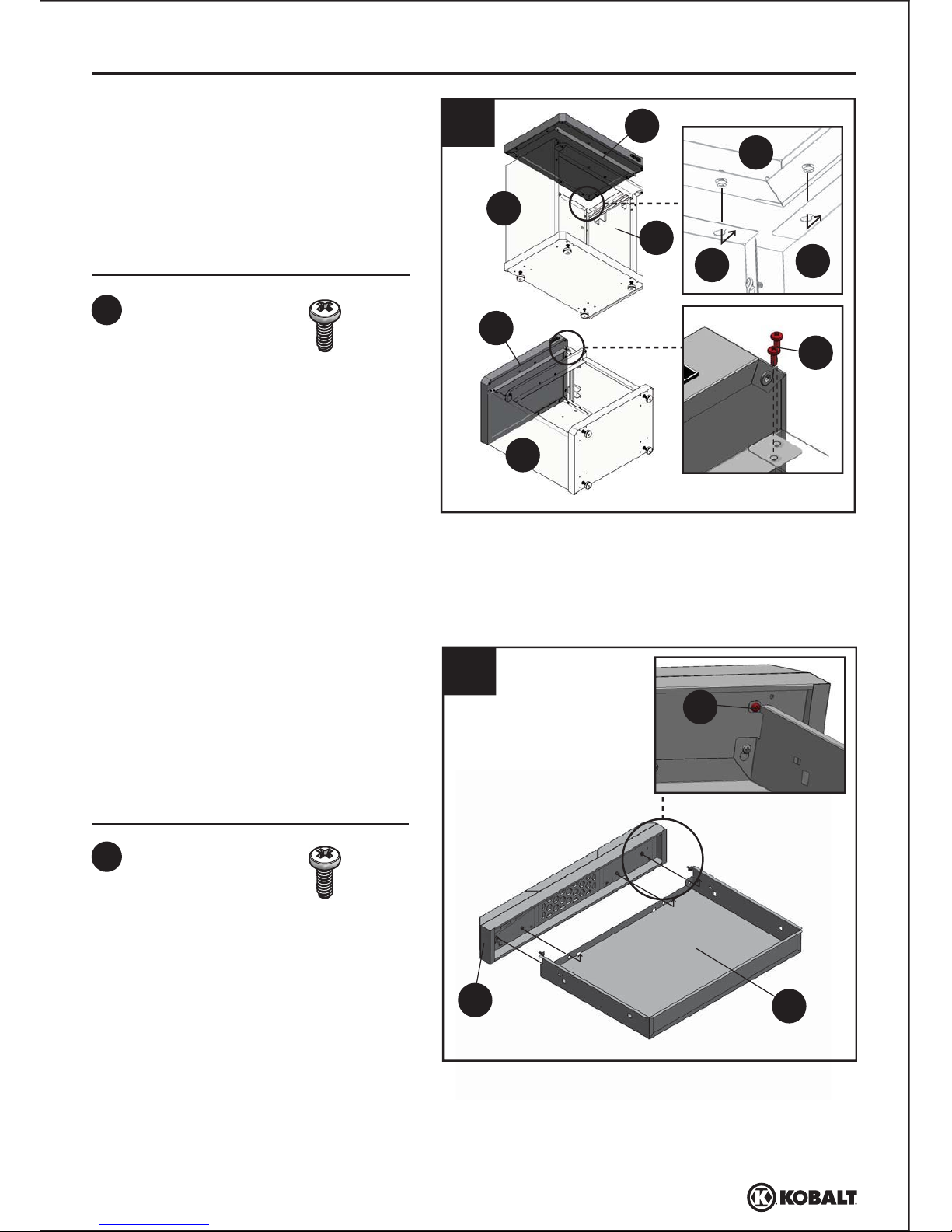
9.
Slide and tighten the preassembled
screws in the top (D) to the assembled
unit. Tighten ST4.8 x 10 mm screws
(AA) to the front edge of top (D) to
connect the left side (B) and right side
(C) to top (D).
10.
Slide preassembled screws on the
drawer front (K) to the key slots in the
drawer (L). Tighten the screws. Use
ST4.8 x 10 mm screws (AA) to connect
drawer front (K) and top drawer (L).
AA
9
Lowes.com
9
C
D
A
AA
B
B
D
D
C
Page 10
M
N
L
K
N
M
ASSEMBLY INSTRUCTIONS
11
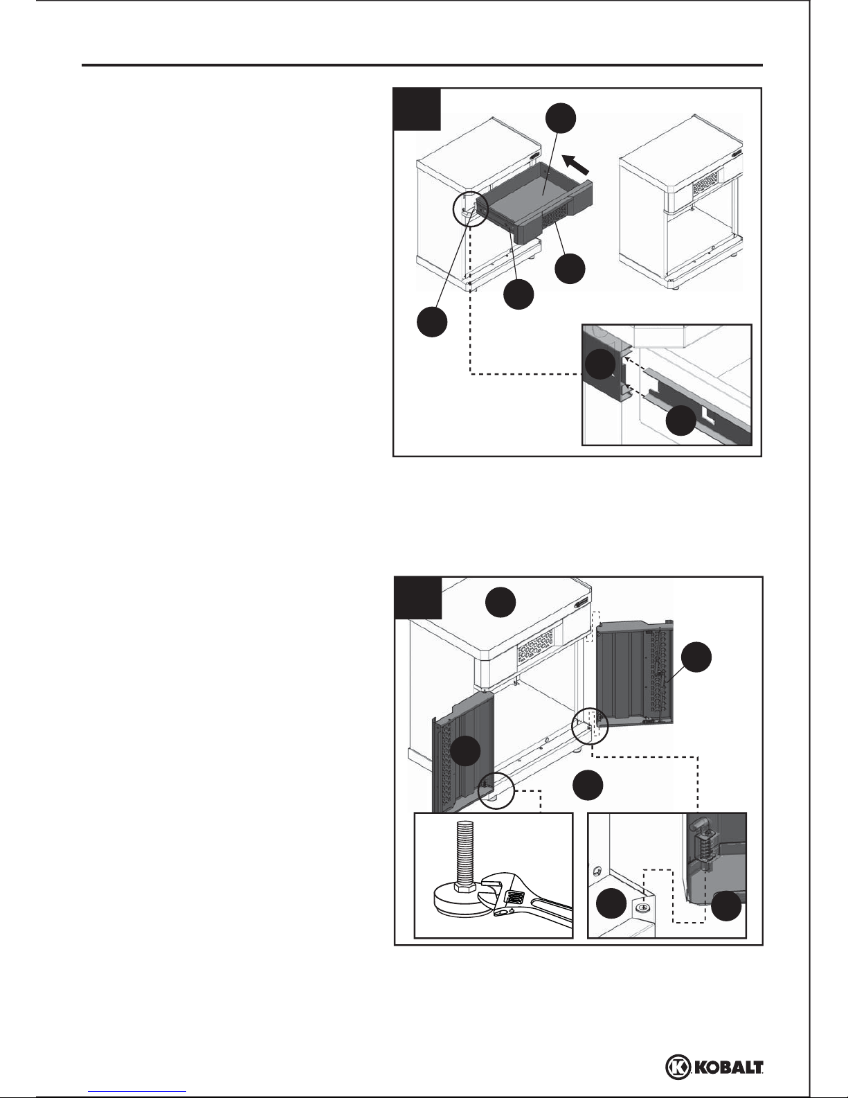
12.
Lift and pull the L-shaped pivot pin on
the edge of the right door (I), aligning
the assembling hole of the base (E)
and top (D), then release. Repeat for
left door (H).
11.
Align the inside slide (N) of the drawer
(L) to the previously installed outside
slide (M), then push the drawer (L)
completely into the assembled unit.
Note: You will need to flip the latch in the
middle of drawer front (K) to close or
open the assembled drawer.
Note: Check and see if the top (D) is level.
If not level due to uneven floor, the two
doors will probably not be properly
aligned. In this case, use an adjustable
wrench (not included) to adjust the hex
nut until the top (D) is level.
10
Lowes.com
I
D
E
H
I
E
12
Page 11
ASSEMBLY INSTRUCTIONS
EE
OPTIONAL K-RAIL MOUNTING INSTRUCTIONS
13
1
Hardware Used
A
D
EE
x 1
x 2
x 2
x 2
Wall strap
BB
#8-32 x 3/8 in. Bolt
CC
#8-32 Nut
DD
ST4 x 20 mm
Screw
1. Ensure wall studs are plumb and
square. Place the
K-Rail® (Item
#0103683, sold
separately) on the wall
studs at the desired location, with the
center of the
K-Rail® a minimum of
30-1/2 in. from the floor. Level the
K-Rail® and mark the location.
K-Rail
®
must be attached to a minimum of 3
wall studs. Attach the
K-Rail® to the
wall studs at the marked locations
using two wood screws (not provided)
per stud.
Minimum
30-1/2 in. from
the floor
13.
Screw one end of wall strap (EE) to
the upper side of back (A) with
#8-32 x 3/8 in. bolts (BB) and #8-32
nuts (CC). Secure the other end to the
wall with ST4 x 20 mm screws (DD).
DD
BB
CC
EE
Note: This cabinet should be anchored to
the wall using the wall strap (EE) to avoid
any potential danger from cabinet falling.
Check and see if the top (D) is level. If not
level due to uneven floor, the two doors
will probably not be properly aligned. In
this case, use an adjustable wrench (not
included) to adjust the hex nut until the
top (D) is level.
Wall
11
Lowes.com
Page 12
D
OPTIONAL K-RAIL MOUNTING INSTRUCTIONS
2
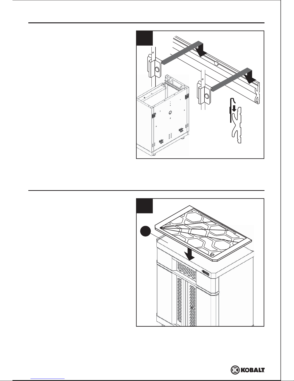
2. Position the bottom outside cabinet
brackets onto
K-Rail® as shown.
Lift the cabinet and insert the top
outside cabinet brackets into the
K-Rail® on the top.
1. Place the Wood Work Surface (Item
#0114853, sold separately) onto the
top of the assembled unit.
OPTIONAL WOOD WORK SURFACE INSTUCTIONS
1
NOTE: If the cabinet spacers do not rest
on a finished wall or on wall studs,
additional wall support may be needed to
properly level the cabinet.
12
Lowes.com
Page 13
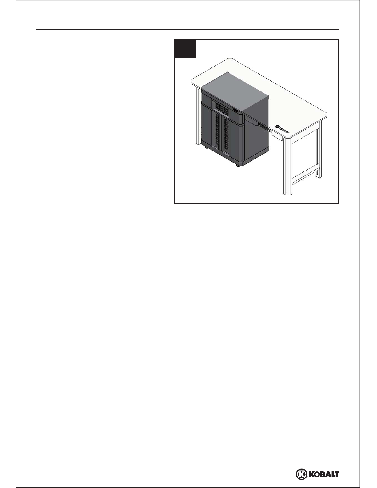
1. Push the assembled cabinet under
Work Table (Item #0595505, sold
separately).
OPTIONAL PLACING UNDER WORK TABLE INSTRUCTIONS
1
NOTE: Need adjust the assembled
cabinet’s height to between 35.8 in.
to 36.6 in.
13
Lowes.com
Page 14

LIFETIME HASSLE-FREE GUARANTEE
REPLACEMENT PARTS LIST
For replacement parts, call custom service at 1-888-3KOBALT, 8 a.m. - 8 p.m., EST, Monday - Friday.
TROUBLESHOOTING
PROBLEM POSSIBLE CAUSE CORRECTIVE ACTION
Screw(s) will not
align into hole(s).
1. Natual properties of sheet
metal cause slight changes in
pre-drilled hole location.
1. Unit is not level. 1. Remove the unit from the wall
and ensure the studs are plumb
and square.
1. Place screws into all aligned holes
and hand tighten. Push a 3/8 in.
hole-punch through both holes to
force the alignment. With the
hole-punch in place, tighten all other
screws. When the hole-punch is
removed, the screw(s) should easily
fit into the remaining hole(s).
Doors will not
remain closed.
PART PART #
A
B
C
D
E
F
G
H
I
J
K
L
M
Back
Left side
Right side
Top
Base
Bottom shelf
Cabinet divider
Left door
Right door
Leg leveler assembly
Drawer front
Drawer
Outside slide
595496-A
595496-B
595496-C
595496-D
595496-E
595496-F
595496-G
595496-H
595496-I
595496-J
595496-K
595496-L
595496-M
595496-N
595496-O
595496-P
595496-Q
595496-AA
595496-BB
595496-CC
595496-DD
595496-EE
595496-FF
595496-GG
595496-HH
DESCRIPTION PART
N
O
P
Q
AA
BB
CC
DD
EE
FF
GG
HH
Inside slide
Door magnet
Door L shape pivot pin
Spring
ST4.8 x 10 mm screw
#8-32 x 3/8 in. bolt
#8-32 Nut
ST4 x 20 mm screw
Wall strap
Lock
Key
Electrical bushing
DESCRIPTION PART #
This product carries a lifetime warranty. If the product is found to be defective, please call
1-888-3KOBALT, 8 a.m. - 8 p.m., EST, Monday - Friday, or return the item to the place of
purchase with a copy of the original sales receipt. The distributor will, at its option, repair or replace
the product. This warranty gives you specific legal rights, and you may have other rights that vary
from state to state.
14
Lowes.com
Printed in China
KOBALT® and the K Design® are registered
trademarks of LF, LLC. All Rights Reserved.
Page 15

15
ARTICLE #0595496
MODÈLE #0056643
ARMOIRE À
1 TIROIR ET
À 2 PORTES
Lowes.com
Numéro de série Date d’achat
JOIGNEZ VOTRE REÇU ICI
Des questions, des problèmes, des pièces manquantes? Avant de retourner l’article
au détaillant, appelez notre service à la clientèle au 1 888 3KOBALT (1-888-356-2258),
entre 8 h et 20 h (HNE), du lundi au vendredi.
KOBALT® et le motif de K® sont des marques de
commerce déposées de LF, LLC. Tous droits réservés.
Page 16

TABLE DES MATIÈRES
16
Lowes.com
Contenu de l’emballage ...........................................................................................................17
Quincaillerie incluse..................................................................................................................18
Consignes de sécurité .............................................................................................................18
Préparation .............................................................................................................................18
Instructions pour l’assemblage .............................................................................................19
Dépannage ...............................................................................................................................28
Garantie ....................................................................................................................................28
Liste des pièces de rechange .................................................................................................28
Page 17

CONTENU DE L’EMBALLAGE
PIÈCE QUANTITÉ
A
B
C
D
E
F
G
1
1
1
1
1
1
1
1
1
4
1
1
2
2
Panneau arrière
Panneau latéral gauche
Panneau latéral droit
Dessus
Base
Tablette inférieure
Séparateur de l’armoire
DESCRIPTION PIÈCE QUANTITÉ
H
I
J
K
L
M
N
Porte gauche
Porte droite
Panneau frontal du tiroir supérieur
Devant du tiroir
Tiroir
Glissière extérieure (préassemblée)
Glissière intérieure (préassemblée)
DESCRIPTION
17
Lowes.com
C
D
A
B
E
I
H
J
L
M
N
K
G
F
Page 18

18
Lowes.com
CONSIGNES DE SÉCURITÉ
PRÉPARATION
Temps d’assemblage approximatif : 1 heure (en excluant le temps de déballage des pièces)
Outils nécessaires pour l’assemblage (non inclus) :
perceuse, tournevis cruciforme
et clé à molette
Vis
ST4,8 de 10 mm
Qté : 14 + 2
Vis
ST4 de 20 mm
Qté : 2
Courroie de mur
Qté : 1
Verrou
(préassemblé à la porte droite [I])
Qté : 1
Clé
(préassemblée à la porte droite [I])
Qté : 2
AA
BB
CC
DD
EE
FF
Écrou de
8/32 po
Qté : 2
Boulon de
8/32 po x 3/8 po
Qté : 2
MISE EN GARDE
• Ne surchargez pas les tablettes (au plus 45,36 kg), et ne rangez pas d’articles lâches ou lourds sur le dessus de l’armoire.
• Lorsque vous rangez des articles sur la tablette inférieure, répartissez uniformément la charge.
• Ne rangez pas de liquides inflammables dans l’armoire, à moins qu’ils ne soient dans un contenant approuvé et
hermétiquement fermé.
• Ne rangez pas d’essence dans l’armoire, en aucune circonstance.
• Lorsque vous fixez l’armoire au mur, veillez à ce que les montants soient d’aplomb et droits.
• Lorsque vous fixez plusieurs armoires à un mur, vérifiez les codes du bâtiment locaux ou consultez un entrepreneur pour
déterminer la charge maximale que peut contenir votre installation.
AVERTISSEMENT
• Ne vous tenez pas debout sur cette armoire, ne montez pas dessus et ne la modifiez pas. Ne l’utilisez que pour sa fonction
spécifique de rangement.
• Manipulez et assemblez avec soin les pièces en métal.
• Les pièces en métal peuvent avoir des bords ou des coins coupants. Nous vous recommandons l’utilisation de gants
protecteurs.
• N’oubliez pas de toujours utiliser des techniques de levage appropriées pour déplacer l’armoire emballée ou assemblée.
GG
QUINCAILLERIE INCLUSE (grandeur réelle)
Avant de commencer l’assemblage du produit, assurez-vous d’avoir toutes les pièces. Comparez
les pièces avec la liste du contenu de l’emballage et celle de la quincaillerie ci-dessus. S’il y a
des pièces manquantes ou endommagées, ne tentez pas d’assembler le produit. Communiquez
avec le service à la clientèle pour obtenir des pièces de rechange. Nous vous recommandons
d’assembler le produit sur une surface propre et douce, comme un morceau de carton.
Page 19

1
B
B
C
A
A
2
J
E
J
E
FACULTATIF
19
Lowes.com
INSTRUCTIONS POUR L’ASSEMBLAGE
1. Faites glisser les vis préassemblées
dans les orifices à rainures du panneau
arrière (A) afin d’assembler le panneau
latéral gauche (B) et le panneau latéral
droit (C) au panneau arrière (A). Serrez
les vis.
Remarque : Assurez-vous de déposer le
panneau arrière (A) sur une surface
douce, comme un tapis ou un morceau de
carton, afin de ne pas l’égratigner.
Remarque : Assurez-vous que les quatre
pieds sont de niveau avant de passer à
l’étape suivante.
2. Vissez les pieds réglables (J) à la
base (E) jusqu’à ce qu’ils soient bien
serrés.
FACULTATIF
Pour être en mesure de déplacer l’armoire
à volonté, vous pouvez installer roulettes
(article #0112281, vendu séparément)
plutôt que les pieds réglables (J). Il vous
suffit de fixer les roulettes pivotantes à la
base (E) à l’aide des boulons à tête, des
écrous en acier et des rondelles de
blocage qui vous seront fournis à l’achat
des roulettes pivotantes (vendues
séparément).
Page 20

L
4
M
N
20
Lowes.com
INSTRUCTIONS POUR L’ASSEMBLAGE
Quincaillerie utilisée
AA
x 4Vis ST4,8 de 10 mm
3. Poussez et serrez les vis
préassemblées dans les orifices à
rainures du panneau arrière (E),
comme à l’étape 1. Serrez les vis
ST4,8 de 10 mm (AA) à l’avant de la
base (E) pour assembler le panneau
latéral gauche (B) et le panneau latéral
droit (C) à la base (E).
4. Appuyez sur les attaches de plastique
de la glissière intérieure (N) de
manière à pouvoir en détacher la
glissière extérieure (M). Abaissez
l’attache de plastique au côté gauche,
puis faites glisser la glissière
extérieure (M) pour la détacher de la
glissière intérieure (N). Relevez
l’attache de plastique au côté droit,
puis faites glisser la glissière
extérieure (M) pour la détacher de la
glissière intérieure (N).
Panneau latéral gauchePanneau latéral droit
AA
3
C
A
E
E
E
B
B
C
A
C
A
E
Page 21

5
6
G
C
B
AA
M
C
C
M
B
21
Lowes.com
INSTRUCTIONS POUR L’ASSEMBLAGE
Quincaillerie utilisée
AA
x 2Vis ST4,8 de 10 mm
5.
Insérez la languette arrière de la
glissière extérieure (M) dans l’orifice
arrière du côté droit (C), puis
assemblez la languette avant de la
glissière extérieure (M) à l’orifice avant
du côté droit (C).
Répétez les mêmes étapes pour le
côté gauche (B).
6. Poussez les orifices à rainures au bas
du séparateur de l’armoire (G) dans les
vis préassemblées au côté gauche (B)
et au côté droit (C). Serrez les vis.
Vissez deux vis ST4,8 de 10 mm (AA)
dans les deux orifices supérieurs du
séparateur de l’armoire (G) pour
assembler ce séparateur (G) au
panneau latéral gauche (B) et au
panneau latéral droit (C).
Remarque : Assurez-vous que la glissière
extérieure droite (M) se trouve du côté
droit (C) et que la glissière extérieure
gauche (M) se trouve du côté gauche (B).
Page 22

F
E
8
E
C
A
A
C
F
F
F
7
22
Lowes.com
INSTRUCTIONS POUR L’ASSEMBLAGE
Boulons de
carrosserie
Vis à tête bombée
Supports extérieurs
de l’armoire
Supports intérieurs
de l’armoire
Rondelles plates
Rondelles
plates
Écrous à embase
Écrous
hexagonaux
Espaceurs
d’armoire
7.
FACULTATIF
Si vous désirez suspendre l’armoire au
mur, utilisez la traverse K-Rail
®
(article
#0103683, vendu séparément) et
l’ensemble de fixation murale (article
#0345926, vendu séparément), puis
suivez les étapes ci-dessous. Sinon,
passez à l’étape 8. Fixez les boulons de
carrosserie, les écrous à embase, les
rondelles plates, les supports extérieurs
de l’armoire et les supports intérieurs de
l’armoire à l’arrière de l’unité assemblée.
Vissez l’espaceur d’armoire à l’arrière de
l’armoire assemblée avec les vis à tête
bombée, les rondelles plates et les
écrous hexagonaux.
8. Installez la tablette inférieure (F) en
l’inclinant sur le côté et en l'insérant
dans l’armoire. Tout en maintenant la
tablette inférieure (F) en angle, alignez
les entailles de la tablette inférieure (F)
avec les joints arrière formés par le
panneau latéral gauche (B), le
panneau latéral droit (C) et le panneau
arrière (A). Abaissez soigneusement la
tablette inférieure (F) en vous assurant
de superposer sa partie avant avec
l'embase frontale de la base (E).
Remarque : Si les languettes frontales
intérieures ont été aplaties pendant
l’assemblage, ajustez-les à l’aide un
tournevis à tête plate (non inclus).
Page 23

L
K
10
AA
23
Lowes.com
INSTRUCTIONS POUR L’ASSEMBLAGE
9.
Faites glisser et serrez les vis
préassemblées sur le dessus (D) de
l’armoire assemblée. Serrez les vis
ST4,8 de 10 mm (AA) sur le rebord
avant du dessus de l’armoire (D) pour
assembler le panneau latéral gauche (B)
et le panneau latéral droit (C) au
dessus (D) de l’armoire.
10.
Faites glisser les vis préassemblées au
devant du tiroir (K) dans les encoches
en trou de serrure du tiroir (L). Serrez
les vis. Utilisez des vis ST4.8 de 10 mm
(AA) pour assembler le devant du tiroir
(K) au tiroir (L).
Quincaillerie utilisée
AA
x 4Vis ST4,8 de 10 mm
Quincaillerie utilisée
AA
x 2Vis ST4,8 de 10 mm
9
C
D
A
AA
B
B
D
D
C
Page 24

M
N
L
K
N
M
INSTRUCTIONS POUR L’ASSEMBLAGE
11
12.
Levez et tirez le pivot en L situé au
bord de la porte droite (I), en alignant
les orifices d’assemblage de la base
(E) sur ceux du dessus (D), puis
relâchez-le. Faites de même pour la
porte gauche (H).
11.
Alignez la glissière intérieure (N) du
tiroir (L) sur la glissière extérieure (M)
précédemment installée, puis poussez
complètement le tiroir (L) dans l’armoire
assemblée.
Remarque : Vous devrez actionner le
loquet se trouvant au milieu du devant du
tiroir (K) pour ouvrir ou fermer le tiroir
assemblé.
Remarque : Vérifiez que le dessus (D) est de
niveau. S’il n’est pas de niveau en raison d’un
plancher inégal, les deux portes ne seront
probablement pas correctement alignées.
Utilisez alors une clé à molette (non incluse)
afin de régler l’écrou hexagonal jusqu’à ce que
le dessus (D) soit de niveau.
24
Lowes.com
I
D
E
H
I
E
12
Page 25

INSTRUCTIONS POUR L’ASSEMBLAGE
EE
13
1
A
D
13.
Vissez une des extrémités de la courroie
de mur (EE) au partie supérieure du
panneau arrière (A) au moyen de boulons
de 8/32 po x 3/8 po (BB) et d’écrous de
8/32 po (CC). Fixez l’autre extrémité de la
courroie au mur, au moyen de vis ST4 de
20 mm (DD).
DD
BB
CC
EE
Remarque : Afin d’éliminer les dangers que la
chute de l’armoire pourrait causer, cette
dernière doit être fixée au mur à l’aide de la
courroie de mur (EE). Vérifiez que le dessus
(D) est de niveau. S’il n’est pas de niveau en
raison d’un plancher inégal, les deux portes ne
seront probablement pas correctement
alignées. Utilisez alors une clé à molette (non
incluse) afin de régler l’écrou hexagonal
jusqu’à ce que le dessus (D) soit de niveau.
Mur
25
Lowes.com
Quincaillerie utilisée
EE
x 1
x 2
x 2
x 2
Courroie
de mur
BB
Boulon de
8/32 po x 3/8 po
CC
Écrou de 8/32 po
DD
Vis
ST4 de 20 mm
INSTRUCTIONS DE MONTAGE FACULTATIVES POUR LA TRAVERSE K-RAIL
1. Assurez-vous que les montants de
cloison sont d’aplomb et droits. Placez
la traverse
K-Rail® (article #0103683,
vendu séparément) à l’endroit désiré
sur les montants de cloison, en
prenant soin de placer son centre au
moins à 77,47 cm du plancher. Mettez
la traverse
K-Rail® de niveau et
marquez son emplacement. Vous
devez fixer la traverse
K-Rail® au
moins à 3 montants de cloison. Fixez
la traverse
K-Rail® aux montants de
cloison aux emplacements marqués, à
l’aide de deux vis à bois (non fournies)
par montant.
Au moins à
77,47 cm du plancher
au minimum
Page 26

D
2
1
26
Lowes.com
INSTRUCTIONS DE MONTAGE FACULTATIVES POUR LA TRAVERSE K-RAIL
2. Placez les supports extérieurs
inférieurs de l’armoire sur la traverse
K-Rail®, comme le montre l’illustration.
Soulevez l’armoire et insérez les
supports extérieurs supérieurs dans le
support supérieur de la traverse
K-Rail®.
1. Placez surface de travail en bois
(article #0114853, vendu séparément)
sur le dessus de l’armoire assemblée.
FACULTATIF : D’INSTALLATION POUR SURFACE DE TRAVAIL EN BOIS
REMARQUE : Si les espaceurs d’armoire
ne tiennent pas en place sur un mur fini ou
des montants de cloison, vous devrez
probablement ajouter un support de mur
pour mettre l’armoire de niveau de
manière appropriée.
Page 27

1. Poussez l’armoire assemblée sous la
table de travail (article #0595505,
vendu séparément).
INSTRUCTIONS POUR LA MISE EN PLACE DE L’ARMOIRE SOUS LA TABLE DE TRAVAIL (FACULTATIF)
1
REMARQUE : Ajustez la hauteur de
l’armoire assemblée afin qu’elle soit de
90,93 à 92,96 cm.
27
Lowes.com
Page 28

GARANTIE À VIE SANS TRACAS
LISTE DES PIÈCES DE RECHANGE
Pour obtenir des pièces de rechange, communiquez avec notre service à la clientèle au
1 888 3KOBALT, entre 8 h et 20 h (HNE), du lundi au vendredi.
PIÈCE PIÈCE #
A
B
C
D
E
F
G
H
I
J
K
L
M
Panneau arrière
Panneau latéral gauche
Panneau latéral droit
Dessus
Base
Tablette inférieure
Séparateur de l’armoire
Porte gauche
Porte droite
Panneau frontal du tiroir supérieur
Devant du tiroir
Tiroir
Glissière extérieure
595496-A
595496-B
595496-C
595496-D
595496-E
595496-F
595496-G
595496-H
595496-I
595496-J
595496-K
595496-L
595496-M
595496-N
595496-O
595496-P
595496-Q
595496-AA
595496-BB
595496-CC
595496-DD
595496-EE
595496-FF
595496-GG
595496-HH
DESCRIPTION PIÈCE
N
O
P
Q
AA
BB
CC
DD
EE
FF
GG
HH
Glissière intérieure
Aimant de porte
Tige de pivot en L pour porte
Ressort
Vis ST4,8 de 10 mm
Boulon de 8/32 po x 3/8 po
Écrou de 8/32 po
Vis ST4 de 20 mm
Courroie de mur
Verrou
Clé
Embout électrique
DESCRIPTION PIÈCE #
Ce produit est couvert par une garantie à vie. Si le produit présente des défauts, veuillez appeler
au 1 888 3KOBALT, entre 8 h et 20 h (HNE), du lundi au vendredi, ou retourner l’article à l’endroit
où vous l’avez acheté; une copie du reçu de vente original vous sera demandée comme preuve
d’achat. Le distributeur choisira de réparer ou de remplacer le produit.
28
Lowes.com
Imprimé en Chine
KOBALT® et le motif de K® sont des marques de
commerce déposées de LF, LLC. Tous droits réservés.
DÉPANNAGE
PROBLÈME CAUSE POSSIBLE MESURE CORRECTIVE
1. Les propriétés naturelles de
la tôle entraînent de légères
modifications de l’emplacement
des avant-trous.
1. L’armoire n’est pas de niveau. 1. Retirez l’armoire du mur et
assurez-vous que les montants
sont d’aplomb et droits.
1. Placez les vis dans tous les trous
alignés et serrez-les à la main.
Placez un emporte-pièce de 3/8 po
dans un trou pour forcer l’alignement.
En maintenant l’emporte-pièce en
place, serrez toutes les autres vis.
Une fois que vous avez retiré
l’emporte-pièce, vous devriez pouvoir
insérer facilement la vis dans le trou.
Les portes ne
restent pas fermées.
La ou les vis ne
s’alignent pas sur
le ou les trous.
Page 29

29
ARTÍCULO #0595496
MODELO #0056643
GABINETE
DE 1 GAVETA
Y 2 PUERTAS
Lowes.com
Número de serie Fecha de compra
ADJUNTE SU RECIBO AQUÍ
¿Preguntas, problemas, piezas faltantes? Antes de volver a la tienda, llame a nuestro
Departamento de Servicio al Cliente al 1-888-3KOBALT (1-888-356-2258), de lunes a
viernes de 8 a.m. a 8 p.m., hora estándar del Este.
KOBALT® y K Design® son marcas registradas
de LF, LLC. Todos los derechos reservados.
Page 30

ÍNDICE
30
Lowes.com
Contenido del paquete.............................................................................................................31
Aditamentos.............................................................................................................................32
Información de seguridad .......................................................................................................32
Preparación ...........................................................................................................................32
Instrucciones de ensamblaje ...................................................................................................33
Solución de problemas...............................................................................................................42
Garantía....................................................................................................................................42
Lista de piezas de repuesto ....................................................................................................42
Page 31

CONTENIDO DEL PAQUETE
A
B
C
D
E
F
G
1
1
1
1
1
1
1
1
1
4
1
1
2
2
Parte posterior
Lado izquierdo
Lado derecho
Cubierta
Base
Repisa inferior
Divisor del gabinete
H
I
J
K
L
M
N
Puerta izquierda
Puerta derecha
Parte frontal de la gaveta superior
Parte frontal de la gaveta
Gaveta
Deslizador exterior (preensamblado)
Deslizador interior (preensamblado)
31
Lowes.com
PIEZA CANTIDADDESCRIPCIÓN PIEZA CANTIDADDESCRIPCIÓN
C
D
A
B
E
I
H
J
L
M
N
K
G
F
Page 32

32
Lowes.com
INFORMACIÓN DE SEGURIDAD
PREPARACIÓN
Tiempo estimado de ensamblaje: 1 hora (no incluye el tiempo de desembalaje)
Herramientas necesarias para el ensamblaje (no se incluyen):
Taladro, destornillador phillips,
llave inglesa
Tornillo
ST4,8 x 10 mm
Cant. 14 + 2
Tornillo
ST4 x 20 mm
Cant. 2
Banda para pared
Cant. 1
Seguro
(preensamblado a la puerta derecha (I))
Cant. 1
Llave
(preensamblada a la puerta derecha (I))
Cant. 2
AA
BB
CC
DD
EE
FF
Tuerca
#8-32"
Cant. 2
Perno
#8-32" x 3/8"
Cant. 2
PRECAUCIÓN
• No sobrecargue la repisa (45,36 kg máx.) ni almacene artículos sueltos o pesados en la cubierta de la unidad.
• Cuando almacene artículos en la repisa inferior, distribuya el peso de manera uniforme.
• No almacene líquidos inflamables en la unidad a menos que estén aseguradas en un envase aprobado.
• No almacene gasolina en la unidad bajo ninguna circunstancia.
• Cuando monte la unidad en la pared, asegúrese de que los montantes estén a plomo y a escuadra.
• Si va a montar varias unidades en una pared, revise los códigos de construcción locales o consulte con contratista
para determinar la capacidad de carga máxima para la ubicación deseada.
ADVERTENCIA
• No se pare, pise ni modifique esta unidad para ningún uso que no sea la función de almacenamiento
para la que se diseñó.
• Tenga cuidado al manipular y ensamblar las placas de metal.
• El metal puede tener bordes o esquinas afiladas. Se recomienda el uso de guantes de protección.
• Siempre recuerde usar técnicas adecuadas de levantamiento cuando mueva la unidad ya sea en su
caja o una vez ensamblada.
GG
ADITAMENTOS (se muestran en tamaño real)
Antes de comenzar a ensamblar el producto, asegúrese de tener todas las piezas. Compare las
piezas con la lista del contenido del paquete y la lista de aditamentos anteriores. No intente
ensamblar el producto si falta alguna pieza o si estas están dañadas. Póngase en contacto con
el Departamento de Servicio al Cliente para obtener piezas de repuesto. Se recomienda que
este producto se ensamble sobre una superficie limpia y suave; como un trozo de cartón.
Page 33

1
B
B
C
A
A
2
J
E
J
E
33
Lowes.com
INSTRUCCIONES DE ENSAMBLAJE
1. Introduzca los tornillos preensamblados
en las ranuras de la llave de la parte
posterior (A) para conectar el lado
izquierdo (B) y el lado derecho (C) con
la parte posterior (A). Apriete los
tornillos.
Nota: Asegúrese de mantener la parte
posterior (A) sobre una superficie suave,
como una alfombra o un trozo de cartón
para evitar rayones.
Nota: Asegúrese de que las cuatro patas
están niveladas antes de seguir con el
siguiente paso.
2. Atornille los ensambles de los
niveladores de las patas (J) a la base
(E) hasta que queden firmes.
OPCIONAL
Para mover la unidad libremente, puede
instalar Ruedas (artículo #0112281, se
venden por separado) en vez de los
ensambles de los niveladores de las
patas (J). Simplemente instale las ruedas
giratorias en la base (E) usando pernos
de acero, tuercas de acero y arandelas
de seguridad que se incluyen en la
compra por separado.
OPCIONAL
Page 34

L
4
M
N
34
Lowes.com
INSTRUCCIONES DE ENSAMBLAJE
Aditamentos utilizados
AA
x 4Tornillo ST4,8 x 10 mm
3. Coloque y apriete los tornillos
previamente ensamblados en la unidad
ensamblada en el Paso 1 en las
ranuras de la llave de la base (E).
Apriete los tornillos T4,8 x 10 mm (AA)
en el borde frontal de la base (E) para
conectar el lado izquierdo (B) y el lado
derecho (C) a la base (E).
4. Jale de los sujetadores de plástico
del deslizador interior (N) para
separar el deslizador exterior (M) del
deslizador interior (N). En cuanto al
sujetador de plástico del lado
izquierdo, presione hacia abajo y
retire el deslizador exterior (M) del
deslizador interior (N). En cuanto al
sujetador de plástico del lado
derecho, presione hacia arriba y
retire el deslizador exterior (M) del
deslizador interior (N).
Lado izquierdoLado derecho
AA
3
C
A
E
E
E
B
B
C
A
C
A
E
Page 35

5
6
G
C
B
AA
M
C
C
M
B
35
Lowes.com
INSTRUCCIONES DE ENSAMBLAJE
Aditamentos utilizados
AA
x 2Tornillo ST4,8 x 10 mm
5.
Inserte la lengüeta posterior del
deslizador exterior (M) en la ranura
posterior del lado derecho (C), luego
ensamble la lengüeta frontal del
deslizador exterior (M) en la ranura
frontal del lado derecho (C).
Repita el paso anterior para el lado
izquierdo (B).
6. Presione la ranura de la llave para
introducirla en la parte inferior del
divisor del gabinete (G) en los
tornillos preensamblados del lado
izquierdo (B) y el lado derecho (C).
Apriete los tornillos. Inserte dos
tornillos ST4,8 x 10 mm (AA) en los
dos orificios superiores del divisor del
gabinete (G) para conectarlo al lado
izquierdo (B) y el lado derecho (C).
Nota: Asegúrese de que el deslizador
exterior derecho (M) esté ensamblado
en el lado derecho (C) y de que el
deslizador exterior izquierdo (M) esté
en el lado izquierdo (B).
Page 36

F
E
8
E
C
A
A
C
F
F
F
8.
Instale la repisa inferior (F) inclinándola
hacia un costado, luego introdúzcala en el
gabinete. Manteniendo la repisa inferior (F)
angulada, alinee los cortes de la repisa
inferior (F) con las uniones posteriores que
forman el lado izquierdo (B), el lado
derecho (C) y el parte posterior (A). Con
cuidado, baje la repisa inferior (F),
asegúrese de que la parte frontal de la
repisa inferior (F) se superponga a la brida
frontal de la base (E).
7
Nota: Si las lengüetas de la repisa frontal
interior se aplanan durante el
ensamblaje, utilice un destornillador
plano (no se incluye) para ajustar las
lengüetas.
36
Lowes.com
INSTRUCCIONES DE ENSAMBLAJE
Pernos cabeza
de hongo
Tornillo de cabeza en cruz
Abrazaderas para
gabinetes exteriores
Abrazaderas para
gabinetes interiores
Arandelas planas
Arandelas
planas
Tuercas de brida
Tuercas
hexagonales
Separador
de gabinetes
7.
OPCIONAL
Si piensa colgar la unidad en la pared
usando el K-Rail
®
(artículo #0103683, se
vende por separado) y Kit para montaje
en pared (artículo #0345926, se vende
por separado), siga el paso que se
presenta a continuación. De lo contrario,
siga con el paso 8. Fije los pernos de
carrocería, las tuercas de brida, las
arandelas planas, las abrazaderas para
gabinetes exteriores y las abrazaderas
para gabinetes interiores a la parte
posterior de la unidad ensamblada.
Atornille el separador del gabinete
usando tornillos de cabeza en cruz,
arandelas planas y tuercas hexagonales
en la parte posterior de la unidad
ensamblada.
Page 37

L
K
10
10.
Deslice los tornillos preensamblados
en la parte frontal de la gaveta superior
(K) hacia las ranuras en la gaveta (L).
Apriete los tornillos. Use tornillos ST4.8
x 10 mm (AA) para conectar la parte
frontal de la gaveta (K) y la gaveta (L).
AA
37
Lowes.com
INSTRUCCIONES DE ENSAMBLAJE
Aditamentos utilizados
AA
x 4Tornillo ST4,8 x 10 mm
9.
Deslice y apriete los tornillos
previamente ensamblados en la cubierta
(D) en la unidad ensamblada. Apriete los
tornillos ST4,8 x 10 mm (AA) en el borde
frontal de la cubierta (D) para conectar el
lado izquierdo (B) y el lado derecho (C)
con la cubierta (D).
Aditamentos utilizados
AA
x 2Tornillo ST4,8 x 10 mm
9
C
D
A
AA
B
B
D
D
C
Page 38

M
N
L
K
N
M
INSTRUCCIONES DE ENSAMBLAJE
11
12.
Levante y tire del pasador giratorio
en forma de L ubicado en el borde de
la puerta derecha (I), alinee el orificio
de ensamblaje de la base (E) y la
cubierta (D), luego suelte. Repita
para la puerta izquierda (H).
11.
Alinee el deslizador interior (N) de la
gaveta (L) con el deslizador exterior
instalado previamente (M), luego
presione la gaveta (L) hasta que
ingrese completamente en el producto
ensamblado.
Nota: Deberá girar el pestillo en la parte
frontal ubicado al medio de la gaveta (K)
para cerrar o abrir la gaveta ensamblada.
Nota: Revise para comprobar que la cubierta
(D) esté nivelada. Si no está nivelada debido a
que el piso no es uniforme, es probable que las
dos puertas no estén alineadas correctamente.
En dicho caso, use una llave inglesa ajustable
(no incluida) para ajustar la tuerca hexagonal
hasta que la cubierta (D) esté nivelada.
38
Lowes.com
I
D
E
H
I
E
12
Page 39

EE
13
1
A
D
DD
BB
CC
EE
Nota: Este gabinete se debe anclar a la pared
con la banda para pared (EE) para prevenir
algún riesgo de que el gabinete se caiga.
Revise para comprobar que la cubierta (D) esté
nivelada. Si no está nivelada debido a que el
piso no es uniforme, es probable que las dos
puertas no estén alineadas correctamente. En
dicho caso, use una llave inglesa ajustable (no
incluida) para ajustar la tuerca hexagonal hasta
que la cubierta (D) esté nivelada.
39
Lowes.com
INSTRUCCIONES DE ENSAMBLAJE
13.
Atornille un extremo de la banda para
pared (EE) en el costado superior de
la parte posterior (A) con pernos
#8/32 x 3/8" (BB) y tuercas #8/32
(CC). Fije el otro extremo a la pared
con tornillos ST4 x 20 mm (DD).
Pared
Aditamentos utilizados
EE
x 1
x 2
x 2
x 2
Banda
para pared
BB
Perno #8-32" x 3/8"
CC
Tuerca #8-32"
DD
Tornillo
ST4 x 20 mm
INSTRUCCIONES PARA MONTAJE CON RIEL EN FORMA DE K
1. Asegúrese de que todos los montantes
estén a plomo y a escuadra. Coloque
el
K-Rail® (artículo #0103683, se
vende por separado) en los montantes
de la pared en la ubicación deseada,
con el centro del
K-Rail® a una
distancia mínima de 77,47 cm del piso.
Nivele el
K-Rail® y marque la
ubicación. El
K-Rail® debe fijarse en un
mínimo de 3 montantes de la pared.
Fije el
K-Rail® en los montantes de la
pared en la ubicación marcada usando
dos tornillos para madera (no se
incluyen) por montante.
A una distancia
mínima de 77,47 cm
del piso
Page 40

D
2
1
40
Lowes.com
INSTRUCCIONES PARA MONTAJE CON RIEL EN FORMA DE K
2. Coloque las abrazaderas del gabinete
inferior exterior en el
K-Rail®, como se
muestra.
Levante el gabinete e inserte las
abrazaderas del gabinete superior
exterior en el
K-Rail®, como se
muestra.
1. Coloque superficie de trabajo en
madera independiente (artículo
#0114853, se vende por separado)
sobre la cubierta de la unidad
ensamblada.
INSTRUCCIONES PARA LA SUPERFICIE DE TRABAJO EN MADERA
NOTA: Si los separadores del gabinete
no descansan en una pared acabada o
montantes de la pared, puede ser
necesario usar soportes adicionales en
la pared para nivelar adecuadamente el
gabinete.
Page 41

1. Empuje el gabinete ensamblado bajo
la mesa de trabajo (artículo # 0595505,
se vende por separado).
INSTRUCCIONES OPCIONALES DE COLOCACIÓN BAJO LA MESA DE TRABAJO
1
NOTA: Necesita ajustar la altura del
gabinete ensamblado entre 90,93 cm y
92,96 cm.
41
Lowes.com
Page 42

GARANTÍA SIN PROBLEMAS DE POR VIDA
LISTA DE PIEZAS DE REPUESTO
Para obtener piezas de repuesto, llame al Departamento de Servicio al Cliente al
1-888-3KOBALT, de lunes a viernes de 8 a.m. a 8 p.m., hora estándar del Este.
PART PART #
A
B
C
D
E
F
G
H
I
J
K
L
M
Parte posterior
Lado izquierdo
Lado derecho
Cubierta
Base
Repisa inferior
Divisor del gabinete
Puerta izquierda
Puerta derecha
Parte frontal de la gaveta superior
Parte frontal de la gaveta
Gaveta
Deslizador exterior
595496-A
595496-B
595496-C
595496-D
595496-E
595496-F
595496-G
595496-H
595496-I
595496-J
595496-K
595496-L
595496-M
595496-N
595496-O
595496-P
595496-Q
595496-AA
595496-BB
595496-CC
595496-DD
595496-EE
595496-FF
595496-GG
595496-HH
DESCRIPTION PART
N
O
P
Q
AA
BB
CC
DD
EE
FF
GG
HH
Deslizador interior
Imán para puerta
Pasador giratorio en forma de L para puerta
Resorte
Tornillo ST4,8 x 10 mm
Perno #8-32" x 3/8"
Tuerca #8-32"
Tornillo ST4 x 20 mm
Banda para pared
Seguro
Llave
Conector eléctrico
DESCRIPTION PART #
Este producto cuenta con una garantía de por vida. Si el producto presenta defectos, llame al a 8
p.m. hora estándar del Este, o devuelva el artículo al lugar de compra junto con una copia del
recibo de venta original.1-888-3KOBALT, de lunes a viernes de 8 a.m. El distribuidor, a su
elección, reparará o reemplazará el producto.
42
Lowes.com
Impreso en China
KOBALT® y K Design® son marcas registradas de LF, LLC.
Todos los derechos reservados.
SOLUCIÓN DE PROBLEMAS
PROBLEMA CAUSA POSIBLE ACCIÓN CORRECTIVA
1. Las propiedades naturales
de la placa de metal causan
ligeros cambios en la ubicación
del orificio pretaladrado.
1. La unidad no está nivelada. 1. Retire la unidad de la pared y
asegúrese de que los montantes
estén a plomo y a escuadra.
1. Coloque los tornillos en todos los
orificios alineados y apriételos a
mano. Coloque un perforador de 3/8"
a través de ambos orificios para
obtener la alineación a presión. Con
el perforador en lugar, apriete los
tornillos restantes. Cuando retire el
perforador, los tornillos deben
ingresar fácilmente en los orificios
restantes.
Las puertas no
se cierran.
Los tornillos no
están alineados
con los orificios.
 Loading...