

KOB PYRTEC SERIES, PYRTEC 950, PYRTEC 1250, PYRTEC 390 Operating And Maintenance Instructions Manual
Page 1
Operating and Maintenance Instructions
PYRTEC 390 to 1250
ID: 105174-F English
Page 2

© by KÖB Holzfeuerungen GmbH
Flotzbachstrasse 33
A-6922 Wolfurt
All rights reserved, including photomechanical
reproduction and storage in electronic media.
Viessmann Group
Page 3

1 General information_________________________________________________ 5
1.1 Foreword _______________________________________________________________________ 5
1.2 Technical standing _______________________________________________________________ 5
1.3 Intended use ____________________________________________________________________ 5
1.4 Technical data___________________________________________________________________ 5
1.5 Information documented __________________________________________________________ 5
1.6 CE- Symbol _____________________________________________________________________ 5
2 Important information _______________________________________________ 6
2.1 Safety information________________________________________________________________ 6
2.2 Excess temperature & power failures________________________________________________ 6
2.3 Lack of water & excess water pressure ______________________________________________ 6
2.4 Fire hazard______________________________________________________________________ 7
2.5 Minimum requirements for wood fuels_______________________________________________ 7
2.6 Filling the fuel storage space_______________________________________________________ 7
2.7 Correcting malfunctions of the feed systems _________________________________________ 7
3 Design____________________________________________________________ 8
4 Control system_____________________________________________________ 9
4.1 Touch screen, Masks 1-8 __________________________________________________________ 9
4.1.1 Navigation_______________________________________________________________________ 9
4.1.2 Mask 1 and how the mask is structured _______________________________________________ 10
4.1.3 Mask 2, Alarm List _______________________________________________________________ 11
4.1.4 Mask 3, Managing the User Status___________________________________________________ 12
4.1.5 Mask 4, Adjusting Settings & Process Parameters_______________________________________ 13
4.1.6 Mask 7, Overview, Wood-powered Boiler______________________________________________ 14
4.1.7 Mask, Additional Boilers ___________________________________________________________ 15
5 Commissioning, Operation & Shut-down ______________________________ 16
5.1 The initial start-up_______________________________________________________________ 16
5.1.1 Inspection before the initial start-up __________________________________________________ 16
5.1.2 The softkeys in Mask 1: ___________________________________________________________ 16
5.2 Heating up without automatic ignition ______________________________________________ 17
5.2.1 Filling the burner trough ___________________________________________________________ 17
5.2.2 Heating up______________________________________________________________________ 17
5.2.3 Fuel >W40______________________________________________________________________ 17
5.2.4 Check of heat up successful?_______________________________________________________ 17
5.3 Heating up with automatic ignition _________________________________________________ 17
5.4 Operation______________________________________________________________________ 17
5.4.1 Full load operation _______________________________________________________________ 17
5.4.2 Output control ___________________________________________________________________ 17
5.4.3 Sustain ________________________________________________________________________ 17
5.4.4 Standby________________________________________________________________________ 17
5.4.5 Transition in output _______________________________________________________________ 18
5.4.6 Switching off ____________________________________________________________________ 18
5.5 Emergency operation ____________________________________________________________ 18
5.6 Measurement operation __________________________________________________________ 18
5.7 Operating modes _______________________________________________________________ 18
Page 4

6 Cleaning/Maintenance______________________________________________ 19
6.1 Boiler _________________________________________________________________________ 19
6.2 Feed systems __________________________________________________________________ 21
7 Shutdowns _______________________________________________________ 22
8 Waste disposal____________________________________________________ 22
9 Enclosures
- Spec Sheet 1010-1, 2
- Malfunction Messages / Correction of Malfunctions
- List of Parameters KPT-MOD
Page 5

5
1 General information
1.1 Foreword
Dear System Owner, you have made a good selection in the PYRTEC. It will provide you with all
the advantages of a modern, economically efficient
heating system. Fully developed technology in
combination with a sturdy design guarantee a high
degree of operational reliability and a long service
life.
These Operating and Maintenance Instructions
contain important information for the intended use,
correct operation and proper maintenance of the
PYRTEC.
Non-compliance with the Operating and Maintenance Instructions will result in loss of the
guarantee.
If you still need any further information after studying the Operating and Maintenance Instructions:
The Assembly and Installation Instructions contain
important information about:
- Standards and regulations
- Structural surroundings of the burner
- Transport and assembly
- Water installation and electrical installation
- Fire protection
- Starting up
as well as an appendix with diagrams of connections and dimensions and the complete technical
specifications.
Our sales and services offices will be glad to provide you with any further information. Their addresses can be found on the reverse side of these
Operating and Maintenance Instructions.
1.2 Technical standing
The Operating and Maintenance Instructions are in
keeping with the PYRTEC at the time it is delivered. In the interest of our customers, we reserve
the right to make, without any notification requirement, subsequent changes resulting from further
technology developments.
1.3 Intended use
The intended use of the PYRTEC is for incinerating wood fuels.
The intended use of the PYRTEC is stipulated:
- in the regulations of the Assembly and Installation Instructions
- by the limits of the technical specifications
- in Spec Sheet 1010 "Minimum Requirements
for Wood Fuels / Instructions",
- by the safety regulations in these Operating
and Maintenance Instructions.
Any other use of the PYRTEC or use of it going
beyond this will be considered as unintended use
unless written approval by the manufacturer has
been obtained.
The following, among other things, will be considered as unintended use:
- Operation of the PYRTEC by unqualified personnel, without any training or knowledge of
the Operating and Maintenance Instructions.
- Disabling the safety or monitoring devices on
the PYRTEC.
- Removal of any protective covers or cladding
on the PYRTEC by unauthorised individuals.
- Making any conversions or alterations to the
PYRTEC without approval by the manufacturer.
- Using spare parts or accessories from other
manufacturers without approval by the manufacturer.
The operating organisation will be liable for
any damage or accidents in case of any unintended use.
1.4 Technical data
The following important limits apply to the
PYRTEC heating boiler:
- Max. operating pressure allowed............ 6.0 bar
- Max. boiler temperature allowed...............100°C
- Min. return temperature ..............................65°C
The complete technical specifications are listed in
the appendix of the Assembly and Installation Instructions.
1.5 Information documented
The Operating Instructions contain the information
required according to the EC Directive on Machinery 98/37/EEC, Appendix 1, Number 1.7.4.
Issue: 2008-04_English
Prepared by: ShlM
1.6 CE- Symbol
The PYRTEC is delivered with a CE-symbol on its
type plate and an EC attestation of conformity in
accordance with Appendix II A of the EC Directive
on Machinery 98/37/EEC.
If the PYRTEC is altered by equipment from other
manufacturers being added, or the safety equipment or control system are combined with a different system and/or integrated into an overriding
system (building control system, etc.), then in the
European Union a new attestation of conformity
has to be issued before it is put on the market.
Page 6

6
2 Important information
2.1 Safety information
When carrying out work on the heating system,
such as cleaning and maintenance, wear appropriate protective equipping when required.
There is a danger of getting injured through:
burning, knocking against corners and edges,
crushing in moving parts and noise.
Mains supply 400V
In dangerous situations, the PYRTEC can be disconnected from the electric mains for all the pins
via the master switch on the control cabinet.
Doors
CAUTION
FIRE HAZARD:
The burner must never be operated with the
doors open! Any burning bits that escape
could start a fire.
CAUTION
DANGER OF INJURY:
If the doors are opened during operation,
sparks and tongues of fire could leap out.
Equipment for dissipating excess heat
The functioning of the thermal run-off safety valve
must be inspected every year by a competent specialist. The safety heat exchanger must not under
any circumstances be used as an operational heat
exchanger.
Seals
For the functioning and controllability of the burner,
it is important that no unwanted air can leak in, entering unchecked through leaky spots.
The doors and lids have to shut tight − any dam-
aged seals must be replaced immediately.
Tighten the retaining screws and handles snugly.
Recirculating flue gas system:
The recirculating flue gas system returns some of
the emissions back into the combustion chamber
under pressure. That is why the piping after the fan
is designed to be pressure-tight. Before it is taken
into operation, the recirculating flue gas system
must be checked for leaks (no gas may escape
when the recirculating fan is in operation and the
flaps are closed).
CAUTION RISK OF CO POISONING from escaping and perhaps odourless gas! Do not permit
operation if the recirculating pipes are leaking!
Operation, cleaning & maintenance
Bear in mind that only if operated and maintained
properly can even the best of products fulfil their
functions well, for a long time and free of malfunctions. Compliance with the "Cleaning" section
is mandatory!
2.2 Excess temperature & power
failures
I M P O R T A N T DANGER of this SUDDENLY
GOING UP IN FLAMES!
Do not open doors or lids on the burner!
- Switch on additional heat consumers.
- The exhaust fan goes out of operation.
- The temperature-limiting safety switch triggers.
- The valve for the thermal run-off safety valve
opens at approx. 95°C. The excess heat is
conducted off into the channel.
If the temperature-limiting safety switch (TLSS)
has triggered, then it has to be manually unlocked. The TLSS is situated at the top of the
burner.
To reset, unscrew the black cap and press the button.
IMPORTANT
: Only as of a temperature of approx.
70°C resetting is possible.
Possible causes for excess temperature
:
- Sudden drop in output to zero. Do not turn off
all the heat consumers at the same time.
- Defective component of the system (pump or
valve)
- Incorrect setting on the control module.
- "CYCLE, UNDERFEED AUGER, SUSTAIN
EMBERS" too high (see the section "Load
level" − Output control system − Sustain embers)
2.3 Lack of water & excess water
pressure
Possible causes:
1. Lack of water: Leakage in the heating system.
2. Excess water pressure: The expansion system
not functioning.
In either case, the facility should be left for a competent heating fitter to check.
Unlock this malfunction with either the reset
button for the water level control system or for
the overpressure monitor, and by pressing the
F1 key (Malfunction) on the control panel in the
control cabinet door.
Page 7

7
2.4 Fire hazard
With underfeed firing systems, the conveying route
creates a connection between the silo and the
burning material in the burner. With the PYRTEC,
the underfeed auger is also the metering auger,
and is thus always filled up with material during
operation. There are various safety devices provided to prevent burn-back.
Temperature sensors:
By means of temperature sensors on the underfeed auger, in case of excess temperature the
loading to the underfeed auger is interrupted, and
the underfeed auger's material is inserted into the
combustion chamber.
Slide valve (option):
This closes in case of a standstill, danger of burnback or power failure (spring return motor).
Rotary valve (option):
Instead of a slide valve, in silos with pressurisation.
Drop-off route:
A vertical drop-off route interrupts the connected
line of burning material.
Fire-extinguishing system (option):
This system, which functions independently of the
electrical power, brings about a flooding of the material to be burned that is located in the underfeed
auger. The activation temperature is approx.
95°C.
2.5 Minimum requirements for wood
fuels
The PYRTEC is only suitable for incinerating the
fuels listed in Spec Sheet 1010 "Minimum Re-
quirements for Wood Fuels" (see enclosure).
If different fuels are used, KÖB will not assume
any liability for the functioning or service life of
the burner. Refer to the "Warranty" section in
the General Terms and Conditions of Delivery.
2.6 Filling the fuel storage space
Rotary sweep extraction and spring-operated
extraction
Switch off the facility using the function button on
the control panel and wait until there is no more
fuel in the feed auger. Fill the silo evenly
to
approx. 30 cm above the articulated arm or over
the spring-mounted blades, switch on the facility
using the function button on the control panel and
wait until the articulated arms or the springmounted blades go under the cup washer.
If any excess or negative pressure can develop in
the silo when the filling is being carried out, at this
point the facility has to be switched off again using
the function button on the control panel. After doing so, finish filling the silo evenly
and switch the
facility back on using the function button on the
control panel.
Carry out refilling in the same manner.
Pellet extraction auger
Switch off the facility using the function button on
the control panel and wait until there is no more
fuel in the feed auger. Slowly
and evenly fill the
silo until the extraction auger is covered approx. 25
cm to 30 cm high over the entire open area. Level
out any mounds that form from pouring. Switch on
the facility using the function button on the control
panel and wait until the metering container on the
feed auger has filled.
If any excess or negative pressure can develop in
the silo when the filling is being carried out, at this
point the facility has to be switched off again using
the function button on the control panel. After doing so, finish filling the silo slowly
and evenly. The
facility can then be switched back on using the
function button on the control panel.
Carry out refilling in the same manner.
2.7 Correcting malfunctions of the
feed systems
The cause of motor malfunctions in feed systems
is usually clogging by large pieces of wood or foreign matter.
CAUTION
DANGER OF INJURY:
Always turn off the master switch before carrying out any repair of a malfunction on feed systems and every time before a maintenance lid
is opened or a protective device is removed!
Due to the facility's automatic operation, the point
in time for the conveying means to be switched on
is not foreseeable.
Page 8
8
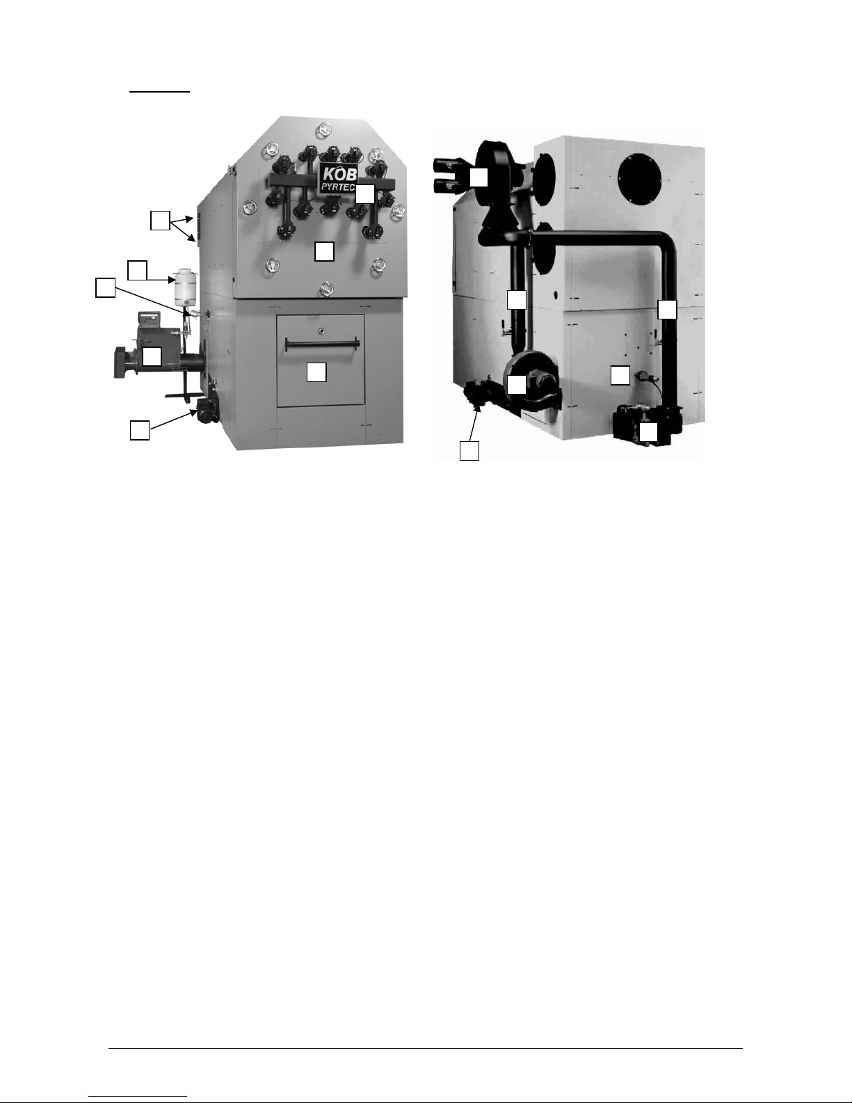
3 Design
(Fig. PYRTEC 950, slide-in module on left) (Fig. PYRTEC 950 special-purpose design with re-
circulated flue gas)
(1) Combustion chamber door
(2) Pipe heat exchanger door
(3) Slide-in module
(4) De-ashing auger (optional)
(5) Extinguisher water container
(6) Cleaning lid
(7) Secondary fan
(8) Recirculated flue gas fan (optional)
(9) Grate drive motor
(10) Ignition fan
(11) Cleaning system (optional)
(12) Combustion box sensor
(13) Recirculated flue gas pipe
In models without the recirculated flue gas function, instead of the fan (item 8), two smaller fans are mounted
directly on the boiler. In such case there are no recirculated flue gas pipes (item 13).
1
2
3
4
5
6
4
7
8
9
10
11
12
13
13
Page 9
9
4 Control system
The control system for the Pyrtec furnace firing process (Pyrocontrol) is effected via a freely programmable
SPS, which makes use of a visualisation system on a touch screen as the interface for navigation and parameterising.
4.1 Touch screen, Masks 1-8
The touch screen is 16 cm wide, 12 cm high and has a resolution of 640x480 pixels. The screen is a colour
display monitor. After switching on the masterswitch, the SPS starts up, and the Overview appears (Mask 1).
4.1.1 Navigation
The navigation program "Pyrocontrol" is a product of KÖB Holzfeuerungen GmbH. It is operated following
the same patterns as MS Windows programs. The selection of the softkey desired can be made with a fingertip or even more exactly with a fingernail.
The arrangement of the softkeys is always the same throughout, i.e. once a keypad occurs, it is located at
the same position in all the masks, with the exception of the BACK key (arrow in blue circle) in Masks 7 and
8.
The hierarchy of Masks 1-7 (optional 8) ranges over the following levels:
Mask 1 Overview
Mask 3
Mask 2
Alarm List
Change User
Status
Mask 4 Mask 7 Mask 8 (option)
Settings Overview, Wood-
powered Boiler
Overview, Addi-
tional Boilers
In Mask 1 you can choose between 7 or 8 different masks (8 being for an optional additional boiler).
When choosing by tapping one of the two boiler softkeys (photo and optional symbol), either 7 "Overview of
wood-powered boiler" or, optionally, 8 "Overview of additional boilers" appears (optional only with multipleboiler systems) in the mask title.
All Masks 1-8 can be parameterised in detail by touching the respective softkeys provided. Doing so opens
new windows in turn, and new input fields or softkeys are provided.
Page 10

10
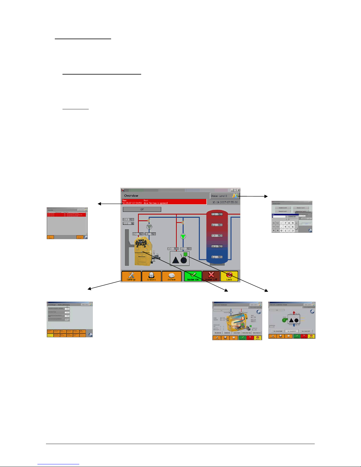
4.1.2 Mask 1 and how the mask is structured
The following applies to all the masks. The mask title and user status are shown at the top. In the mask title
you can tell which mask (1-8) you are in. In the centre of the mask the areas for display and call-up are always located for inputting parameters. The softkeys for navigation and input are located at the bottom, with
the exception of the combined user status display and the call for input.
Changeable softkeys for input are white (light). Display windows are always grey (dark). Softkeys for navigation are always provided in colour to select from.
Area of
mask
Mask 1 Overview Description
Top
Centre
Bottom
Mask title, e.g. "Overview"
User status (top right)
Alarm line (bottom left, red)
Date/Time (bottom right)
Displays of operating mode of KÖB
boiler (top left, grey),
e.g. "OFF" (no heating operation)
Display of actual value of boiler (grey):
Exhaust gas temperature (top left),
Residual O
2
(bottom left)
Displays of buffer charge state (grey)
Button for KÖB boiler (photo)
With object indicator lamps
(green/grey)
Button for additional boilers (option)
Sets of buttons, bottom right:
Boiler ON (green)
Boiler OFF (red)
Lock screen (yellow)
Sets of buttons, left bottom:
Navigation (orange) for Masks 4, 5 &
6: Settings, Analysis, Archive
Object indicator lamps, Mask 1:
Boiler pump and display of operational status of additional boilers. If the object indicator lamp lights up
green, then there is activity. Example: The pump is running and an additional boiler is in operation. If the object indicator lamp is grey, the respective object (pump or additional boiler) is shut down.
Important: The object indicator lamp says nothing about the operating mode of the system.
Page 11
11
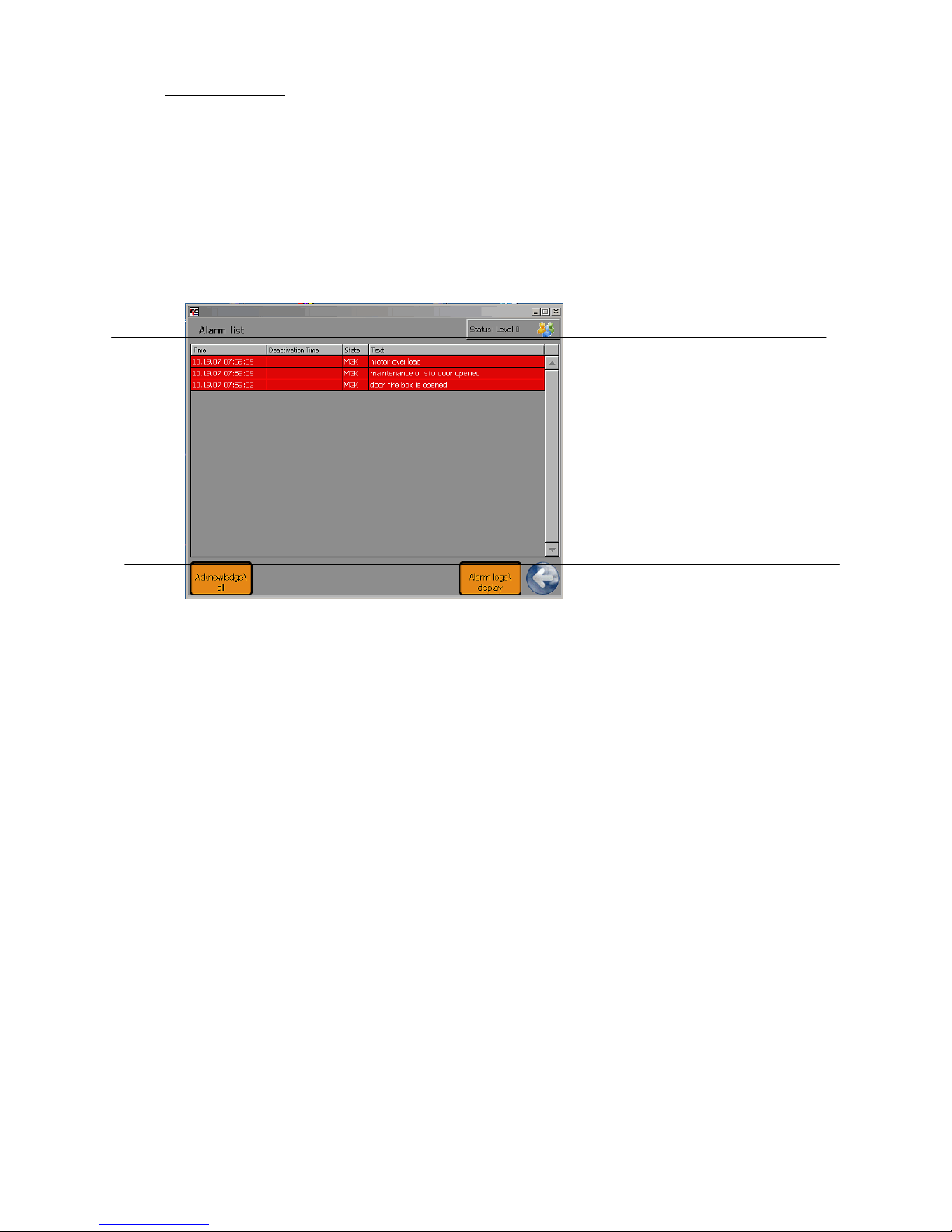
4.1.3 Mask 2, Alarm List
Touching the red Alarm line softkey (in Mask 1) opens Mask 2 (Alarm List with alarm logs, red). Here all the
error messages are shown which have been registered but not yet acknowledged. Touching an alarm log
line chosen allows the respective error message to be displayed in detail or acknowledged.
A history of the error messages acknowledged can be called up in Mask 2.
Area of
mask
Mask 2 Description
Top
Centre
Bottom
Mask title, e.g. "Alarm List"
User status (top right)
Alarm logs (red) in rows according to
time
Back button (back to Mask 1)
Display alarm logs
Acknowledge all
The "Acknowledge all" softkey (bottom left) acknowledges the error messages listed in the centre of the
mask. The cause of the error should be remedied before acknowledging the error message. Otherwise the
error message will continue to be maintained. (It will be shown again in the Alarm List in a short period of
time.)
Touching the softkey "Display alarm log" (bottom right) will list all the past error messages. The softkey "Ascertain alarms in history" is displayed in the lower left of this new page. By touching this softkey, the period
can be specified in which the alarms saved are to be displayed.
Page 12
12
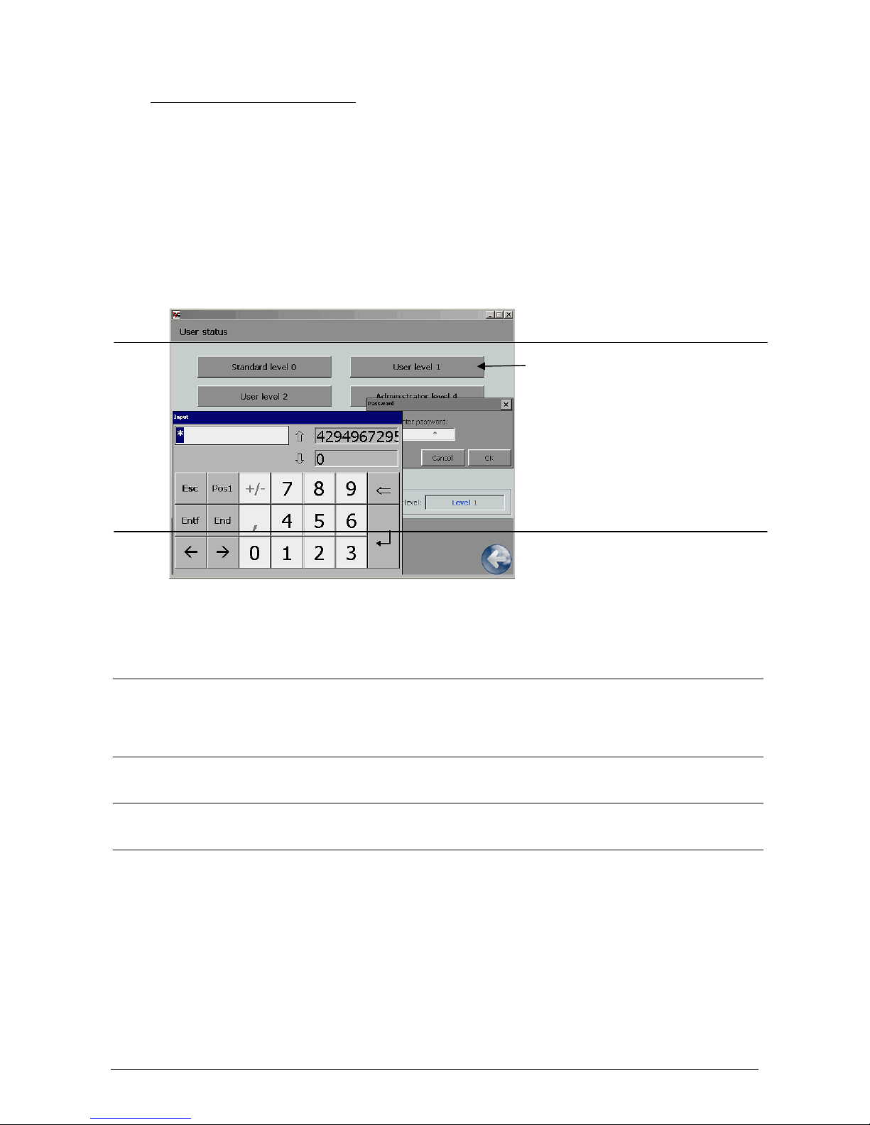
4.1.4 Mask 3, Managing the User Status
Touching the softkey "Status Level 0", …1, 2 or 4 (at the top right of the mask), the user level can be
changed and thus the access rights for parameterising stipulated. To change the user level, no user name
need be entered, but rather all four possible levels are provided as buttons. When the user level desired (0-
4) is selected, a password in the form of a 4-digit code will be asked for, which has to be entered and confirmed with ENTER by touching the white input cell using the pop-up number keypad. The password will then
appear in four asterisks (****) and has to be confirmed again with OK.
Area of
mask
Mask 3 Description
Top
Centre
Bottom
Mask title "User Status"
Softkeys for selecting the user level
desired
Password query window: Always con-
firm with OK.
Input number keypad: Enter the 4-digit
code here and confirm with ↵ .
Display: current level
Back button (back to Mask 1)
After making these entries, the newly selected status applies with the following user rights associated with it:
User level Password Rights
Standard Level 0
No password (Æ automatic
jump back to standard after
standstill period > 5 minutes).
No rights, no changing (only display)
Customer Level 1
1111
No selection of parameters with the trend display
(Point 5.1)
Customer Level 2
2222
Parameter selection is possible
Administrator Level 4 No specification
Administrator, access to WinCE Desktop as well as
software updating possible
By introducing these user levels, KÖB Holzfeuerungen GmbH is making an effort to maintain the parameters
essential for quality-assured businesses. This guarantees good operational practice, as certain parameter
changes are reserved only for KÖB technicians. This gives the user greater certainty that one cannot accidentally make any changes that would be technically less favourable.
Page 13
13
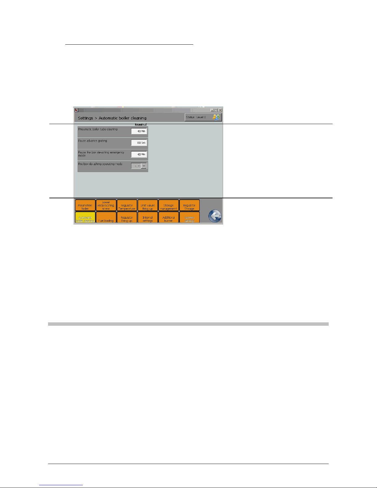
4.1.5 Mask 4, Adjusting Settings & Process Parameters
In Settings, adjustable categories can be chosen and their parameters changed.
In the centre the parameters to be set are listed with their currently applicable values.
Area of
mask
Mask 4, Settings Description
Top
Centre
Bottom
Mask title "Settings >
AutoBoilerCleaning" (left)
User status (right)
Display
Parameters set
White fields can be changed by touching, provided a valid user status is set.
Softkey categories (orange)
The category activated is coloured yellow. Parameters can then be changed.
Back button (back to Mask 1)
If an attempt is made to change a parameter that is not cleared for change in the current user status, Mask 3
will be called up automatically. By changing the user status, here the authorisation required can be cleared
(see Changing User Status 4.1.4).
The value changes when the white "Setting input cell" is touched, which opens a pop-up number keypad.
Enter the value desired and confirm with ↵ . The new value is immediately valid in the furnace-firing and/or
heat recovery process. If the value selected is outside the setting range, then the maximum or minimum
value possible will be automatically accepted.
Factory setting (default setting)
All the parameters in the Pyrocontrol, such as set point values and switching times, are already pre-set and
can be produced in Mask 4 as "Set-point values".
The values of the factory setting can be restored in User Level 2 or higher in the internal settings.
Page 14

14
4.1.6 Mask 7, Overview, Wood-powered Boiler
Touching the KÖB Boiler softkey (photo in Mask 1) opens Mask 7 (sectional view of the boiler).
Here the most important process parameters, activity modes and operating hours are reproduced. The operating mode display is located in the centre upper left of the screen. (For explanations on the text displays,
see Section 5.7).
Measurement operation, emergency operation and the activity of the de-ashing system as well as that of the
underfeed auger can all be operated manually here.
Area of
mask
Mask 7, Overview, Wood-powered Boiler Description
Top
Centre
Bottom
Mask title, e.g. "Overview, Woodpowered Boiler"
Alarm line (bottom left, red)
User status (top right)
Date/Time (bottom right)
Back button (back to Mask 1)
Displays of operating mode (top left,
grey), e.g. "Load" (heating operation)
Displays of forward/return flow temperature (grey)
Displays of exhaust gas parameters
(right, grey)
Displays of furnace-firing parameters
(grey)
Displays of supply air fan (left, grey)
Object indicator lamps (green/grey)
Displays of operational statistics
Softkeys, bottom right:
Boiler ON (green)
Boiler OFF (red)
Lock screen (yellow)
Softkeys, left bottom:
Navigation (orange) for Masks 2, 3 &
4: Settings, Analysis, Archive
Exhaust gas parameters, centre of screen: Exhaust gas fan power (top), residual oxygen (centre), exhaust gas temperature (bottom)
Object indicator lamps (centre of mask, green or grey squares):
Light barriers for embers and metering container: If the object indicator lamp lights up green, then there is no
blockage of the light barrier. If the object indicator lamp is grey, the light barrier has been blocked (maximum
height of embers reached or metering container full). The object indicator lamp gives no information about
the presence of any malfunction.
Operational statistics: Here the respective sums of operating periods are listed for load, sustenance and
standby.
Softkeys (Mask 7, centre):
Measurement operation (see 5.6)
Emergency operation (see 5.5)
Ash, manual: When the softkey is touched, the colour of the field changes (dark/light). The de-ashing auger
runs until the softkey is touched again or until a change is made to another mask.
Underfeed Stop: When the softkey is touched, the colour of the field changes (dark/light). The supply of
material into the fire box is interrupted until the softkey is touched again or until a change is made to another mask.
Underfeed ON: When the softkey is touched and held, the colour of the field changes (dark/light). Material
is supplied into the fire box until the softkey is released again.
Page 15
15
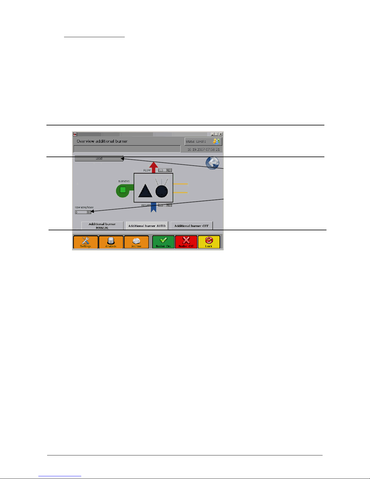
4.1.7 Mask, Additional Boilers
When the softkey for additional boilers is touched (symbol in Mask 1), Mask 8 opens (symbol for oil or gas
boiler, enlarged).
Here the forward flow and return flow temperature of the additional boiler is reproduced. The KÖB Boiler operating mode display is located in the centre upper left of the screen. (For explanations on the text displays,
see Section 5.7).
Here the additional boiler can be manually switched on or off, and automatic operation can be selected. The
operating hours counter is located in the centre left of the screen.
Area of
mask
Mask 8, Overview of Additional Boilers (option) Description
Top
Centre
Bottom
Mask title, "Overview of Additional
Boilers"
Alarm line (bottom right, red)
User status (top right)
Date/Time (bottom right)
BACK key (back to Mask 1)
Displays of operating mode for KÖB
Boiler (top left, grey)
Displays of forward/return flow temperature (grey)
Display for clearance time
Softkeys for addition boilers:
Additional boiler, manual (dark/light)
Additional boiler, automatic (dark/light)
Additional boiler, OFF (dark/light)
Softkeys for KÖB boiler:
Boiler ON (green)
Boiler OFF (red)
Lock screen (yellow)
Softkeys, left bottom:
Navigation (orange) for Masks 4, 5 &
6: Settings, Analysis, Archive
Object indicator lamp (Mask 8, centre):
Clearance for burner: If the object indicator lamp lights up green, then the burner is in operation: If the object
indicator lamp is grey, the burner is inactive. The object indicator lamp gives no information about the presence of any malfunction.
Important: Only in Mask 8 can the additional boiler be switched on, off or to automatic operation. The softkey
selected by touching it will turn light. The operation selected is displayed in the operating mode display.
Important: In Masks 7 and 8 (optional for additional boilers), the BACK keys are positioned in the centre of
the mask.
Page 16

16
5 Commissioning, Operation &
Shut-down
5.1 The initial start-up
The initial start-up is carried out either by KÖB
Holzfeuerungen GmbH or another competent individual named by it.
Be absolutely sure to follow the instructions in
the Assembly and Installation Instructions. No
guarantee may be claimed for damages in
cases of initial start-ups carried out improperly at one's own initiative.
5.1.1 Inspection before the initial start-up
- Is there enough water in the heating system?
- Has the heating system been bled of air?
- Are the slide valves open for the heating-
system's forward and reverse flow?
- Can enough fresh air get into the heating
room?
- Are the doors and lids on the burner all closed
leak-tight?
5.1.2 The softkeys in Mask 1
:
Softkey 1
Switch on boiler
When touched with the finger
or fingernail, the colour
changes (from light to dark)
Softkey 2
Switch off boiler
When touched, a confirmation is requested, and then
the colour changes (from
light to dark).
Softkey 3
Lock screen
Unlock screen
When touched, a confirmation is requested.
Softkey 4
Open settings
Touching it opens Mask 4 for
parameterising.
Softkey 7
Mask for KÖB
boiler
Overview, wood-powered
boiler
Touching it opens Mask 7.
Softkey 8
Symbol
Overview, additional boilers
Touching it opens Mask 8.
Important: Mask 8 is only
available with optional multiple-boiler systems-
Page 17

17
5.2 Heating up without automatic
ignition
5.2.1 Filling the burner trough
When the system has switched off properly, there
is no more fuel in the burner trough or in the underfeed auger.
With the fire block cooled down (fire box temperature below 250°C), touching softkey 1 "Boiler ON"
will automatically fill the burner trough with fuel.
5.2.2 Heating up
Light a fire with paper and kindling wood in the fire
box. After this, use the blade to push the fire back
to the filled burner trough. Then press Softkey 1
"Boiler ON" again (Softkey 1 "Boiler ON" is then
dark green). Operating mode "HEAT UP" shows
in the upper left of the display.
5.2.3 Fuel >W40
- With fuel that has water content greater than
W 40 moist, preheat the boiler with a chopped
wood fire. To do so, manually light chopped
wood in the fire box and use the shovel to
push it into the burner trough. If necessary,
add more chopped wood. Heat up the fireclay
brick lining like this for approx. one hour.
- Starting up the facility: Softkey 1 "Boiler ON"
The softkey "Underfeed ON" is for manually activating the underfeed auger in automatic operation
(= manual prompt for material). As long as this
softkey is touched, the underfeed auger moves
fuel into the burner trough. With the underfeed
auger stopped (softkey "Stop underfeed" lightgrey), the manual prompt for material cannot be
activated.
5.2.4 Check of heat up successful?
The fire box temperature should be over 180°C in
30 minutes (adjustable value). Otherwise the system will automatically shut itself back down. In
such case press Softkey 1 "Boiler ON”.
5.3 Heating up with automatic
ignition
The boiler is simple to switch on:
- Press Softkey 1 "Boiler ON". The loader modules will be switched on in the appropriate order. When the auger filling time or fire box filling time has lapsed and there is enough fuel
in the combustion chamber, the loader system
switches off.
- The automatic ignition then takes place. The
ignition process stops as soon as the fire is
started.
- The boiler then automatically switches to full
load operation. (If the material should be too
moist, it might be necessary to proceed following Item 5.2.3 "Heating up".)
5.4 Operation
5.4.1 Full load operation
As soon as a fire box temperature of approx.
180°C is reached (adjustable value), the system
switches, depending on the boiler temperature, to
operating mode "FULL LOAD" or "SUSTAIN",
which is shown in the upper left of the display.
5.4.2 Output control
The heat output to be produced is adapted to the
heat consumption in a range from 25% to 100% of
the boiler's nominal output. Depending on the deviation of the boiler temperature from the boiler
set-point temperature (75°C to 95°C), the air flow
rate is set by means of a fan with infinitely variable
control. The fire box and residual oxygen control
then resupplies the optimum amount of fuel for
lowest emissions.
If, through a corresponding rise in the boiler temperature, the heat consumption drops below 25%
of the rated output, the system switches to "SUSTAIN", which is shown in the upper left of the display.
5.4.3 Sustain
In the operating mode "SUSTAIN", the exhaust
fan only runs at a minimum speed. The supply air
fans do not run.
The resupplying of material via the underfeed auger has to be greater than the speed of back-burn
and can be set as a set-point value by touching
Softkey 4 "Settings" in Mask 4 (CYCLE for underfeed auger SUSTAIN). This depends on the material (light shavings require more resupplying of
material than do chippings).
"Cycle for underfeed auger sustain" too high:
Too much material is pushed into the burner
trough such that the embers are too large for the
sustain load operation. The further consequence
of this might bring about the malfunction back
burn, excess temperature or overfilling of the fire
box.
"Cycle for underfeed auger sustain" too low
: Too
little material is pushed into the burner trough
such that the embers are too small for the sustain
load operation. This can bring about a back burn
or the fire will go out.
5.4.4 Standby
If too much heat is generated in sustain load op-
eration, the control system automatically goes into
standby operation. When this threshold value is
reached, first the isolating valve shuts, and the
auger module is slowly idled in the sustain mode.
For the standby mode, all the drive activities (fans
and auger modules) are stopped. Only then does
"Standby" appear in the operating mode display.
When the boiler temperature drops or a minimum
standby period lapses, in the case of a prompt an
automatic new start is carried out.
Page 18

18
5.4.5 Transition in output
To obtain a good structure of the fire and thus low
emissions of harmful substances, the switchover
from "SUSTAIN" to "FULL LOAD" is not carried
out suddenly but rather gently.
5.4.6 Switching off
Touching Softkey 2 "Boiler OFF" shuts down the
furnace firing process properly. "Burn-out" is indicated on the display. The firing control system
continues to run until there is no more fuel in the
underfeed auger or the fire box temperature is below the set-point value and then it switches off.
C A U T I O N: Do NOT use the masterswitch to
switch off Æ DANGER OF BACK BURN!
5.5 Emergency operation
The firing optimisation function can be switched
off in Mask 7 by touching the "Emergency operation" softkey. If a sensory mechanism is defective,
the switching off takes place automatically. Text
shown on display: "SYSTEM PRESENTLY RUNNING WITHOUT OPTIMISATION". The quantities
of material and air are then manually set as setpoint values under "Emergency operation output"
and "Emergency operation cycle of underfeed auger". The negative pressure is no longer corrected
automatically. For this reason the fan settings
must be checked. No positive pressure must develop in the burner. In case positive pressure
should develop, adjust the mechanical means of
throttling on the supply air fans.
5.6 Measurement operation
It is possible to switch the boiler control system
into "MEASUREMENT OPERATION" in Mask 7
by touching the softkey "Measurement operation"
while the indicator in the upper left of the display
is indicating "FULL LOAD". In "MEASUREMENT
OPERATION" the output control is blocked to
guarantee constant full load operation during the
measurement.
V E R Y I M P O R T A N T: In measurement
operation the system does not switch to
"SUSTAIN". Ensure heat consumption Æ Danger of excess temperature!
5.7 Operating modes
The following terms are displayed in the operating
mode line depending on the situation:
Off
The boiler is switched off.
Filling
Cold start. The fire box trough is
being filled by the underfeed
auger.
Auger
filling
Direct or hot start with fire box
still warm. The auger module is
being filled.
Igniting
The ignition blower is running.
The system is being started.
Heating up
The system is being slowly
started.
Full load
The boiler is running in regular
operation.
Sustain
Embers being sustained. Boiler
set-point temperature and the
switching threshold "Sustain on"
have been exceeded.
Standby
The boiler temperature is over
the switching threshold for
standby and no prompt.
Auger
idling
The isolating valve moves shut,
the boiler goes into standby.
Example: After malfunctions or
the boiler set-point temperature
being exceeded. Upon a prompt
for heat there will be an automatic new start.
Burn-out
There is a malfunction or Softkey 2 "Boiler OFF" has been
touched.
The fire box is cooling down.
Emergency
operation
Non-optimised operation with
adjustable operational set-point
values. Example: If a sensory
mechanism necessary for optimised operation is defective, the
switchover is being carried out
automatically.
Required sensory mechanisms:
lambda-sensor, fire box temperature sensor & negative
pressure measuring system.
Measurement operation
The output control is blocked to
guarantee constant full load operation during the measurement.
Page 19

19
6 Cleaning/Maintenance
6.1 Boiler
Regular cleaning and maintenance of the facility is the customer's most important job for years of
trouble-free operation and to obtain the greatest possible output with the best efficiency.
Here the cleaning intervals for chip material are listed as per ÖNORM M 7133 with clinging bark –
0.8% ash content. The cleaning intervals may vary, depending on the fuel, the amount of fine matter
and the operating method.
CAUTION – RISK OF INJURY: Before beginning cleaning work, put the facility out of operation. Be
absolutely sure to wear protective gloves, protective eyewear if required and use the cleaning utensils that come with the facility (danger of blow-ups, burns and getting crushed)!
Approx. every 300 operating hours:
Clean the air vents for the burner trough and remove remaining ash from the fire box.
With pneumatic pipe cleaning system, after approx. 600 operating hours; without pneumatic pipe cleaning system, after
approx. 300 operating hours:
Open boiler door and clean all the heat exchanger pipes with
wire cleaning brush.
IMPORTANT
:
With pneumatic pipe-cleaning system, disconnect the compressed air line before opening the boiler door – danger of
injury!
Approx. every 300 operating hours:
Clean the light barriers and inspection
windows above the underfeed auger,
and also opposite. Remove dust and
ash deposits in the openings.
Approx. every 300 operating hours:
Open all the lids on the insertion side or
across from the feed and remove ash.
After each manual
cleaning of the heat
exchanger:
Use kindling utensils to
draw ash to the front and
remove.
After each manual cleaning of
the heat exchanger:
Open lid on both sides and remove
ash.
Approx. every 300 operating hours:
Clean the light barriers and inspection windows above the de-ashing auger (optional),
and also opposite. Remove dust and ash deposits in the openings.
Page 20

20
Pneumatic tube-cleaning system (optional)
- Operation and maintenance of the compressor
(optional) according to the manual that comes
with the facility.
- The timer that comes with the compressor is
for limiting the running time and should be
mounted between the compressor and the
power supply.
- When the compressed air system is provided
by the customer, the compressor has to be
suited for continuous operation or be secured
against continuous operation (e.g. timer for
limiting running time).
- Continuous operation of the compressor indicates leakage in the air system. Check air supply line and valves for leakage.
Exhaust gas deduster (Option)
IMPORTANT: Never operate the boiler without
ash container!
Regularly drain condensation water in the
compressed air distribution bar.
Approx. every 1000 operating hours
Pull out plug, unscrew wing nuts, pull out
motor with impeller and clean with broom
or wire brush.
CAUTION DANGER OF INJURY – Turn
off master switch
Approx. every 300 operating hours
Open lid and clean the deduster´s guide
blades with a hand brusch.
Nach ca. 300 Betriebsstunden (Aschen-
tonne 240 Liter):
Aschenbehälter unterhalb des Entstaubers
After approx. 300 operating hours (240litre ash bin):
Empty ash bin beneath the de-duster.
Page 21

21
Flue gas recirculation system (optional)
6.2 Feed systems
All the geared motors on the feed systems are
maintenance-free.
- A change of lubricant and/or oil is recommended every 20,000 operating hours or every
three years.
- Re-lubricate flange bearings and other lubricating points regularly with lithium soap grease.
- Check chain drives for wear and, if necessary,
tighten them up and lubricate with chain oil.
- Check all the bolts to be sure they are snug.
- Once a year check the extraction components
in the silo and/or bunker for damage and soiling. Remove any foreign matter there might be.
- Check and lubricate rotary sweep extraction
(AG), elbow joints, pivot pins, tension springs
and tension chains; readjust elbow joints if necessary.
- Inclined extraction system (AP / APS)
Lubricate the gasket between the extraction
casing and the geared motor and universal joint
for the auger.
IMPORTANT: Never use inflammable lubricants!
Approx. every 4000 operating hours
Clean recirculated flue gas line
WARNING INFORMATION:
A mixture of emissions and air that may
contain carbon monoxide (CO) and other
toxic odourless gases is produced inside
the recirculating flue gas piping system. Its
pressure is slightly above atmospheric.
Therefore the correct assembly of the
cleaning lids must be checked and the system must be checked for leaks each time
the system has been cleaned (when the recirculating flue gas fan is in operation and
the flaps are closed, no gas may escape).
After around 1800 operating hours (annually):
Checks for leaks must be repeated each
year so that any possible wear on the seals,
particularly in the area of the maintenance
covers, may be recognized and corrected in
time.
Approx. every 4000 operating hours
Clean secondary airflow fan.
CAUTION DANGER OF INJURY – Turn
off master switch
Approx. every 1000 operating hours
Clean recirculated flue gas fan.
CAUTION DANGER OF INJURY –
Turn off master switch
Page 22

22
7 Shutdowns
Heating boiler
Pipe-type heat exchanger
When the PYRTEC is put out of operation for a
long period (such as for summer breaks), be sure
to carefully clean the pipe-type heat exchanger
with a steel brush as required.
Prevent high-temperature corrosion when chipboards are incinerated:
If the heating room is moist or there is any other
atmosphere that promotes corrosion (e.g. poor
ventilation, residual enamel near the heating room,
etc.), after carrying out the cleaning, also spray the
pipe-type heat exchanger with biodiesel.
If there is a danger of frost, empty the heating system, following the heating fitter's rules, or have
anti-frost agent filled.
Control system
Even when the PYRTEC is put out of operation for
long periods, the power supply to the control system should not be interrupted (do not turn off master switch).
Why?
- Avoid the formation of condensation in the
lambda sensor.
- Extend the service life of the buffer battery.
8 Waste disposal
Shutdowns
If necessary, first switch off the PYRTEC using the
F2 key "ON/OFF". When the burn-out has taken
place, and the burner has cooled off, turn off the
master switch.
Disconnect the mains connection to the control
cabinet.
CAUTION: DANGEROUS VOLTAGE!
Only licensed electrical firms are allowed to disconnect and dismantle the connection to the electrical network.
Close the forward flow and return flow slide valves.
- Open the drain tap on the bottom of the boiler
of the PYRTEC and drain water.
Only heating system fitters may drain the boiler
and dismantle the connections to the heating system.
Disconnect the forward flow pipe and return flow
pipe from the PYRTEC.
Instructions for transport to a different location
The personnel who carry out transports to different
locations have to know the dangers involved of accidents that might arise in doing so and use suitable measures to prevent such from happening.
Instructions for waste disposal
Comply with laws and regulations of the land on
disposing waste.
Contract a disposal firm to dispose of and recycle
waste in an environmentally friendly fashion.
Page 23

Spec Sheet
Wood Fuels
Minimum Requirements / Information
KÖB Holzfeuerungen GmbH, Flotzbachstr. 33, A-6922 Wolfurt, Tel. +43/5574/6770-0, Fax 65707, E-Mail: office@kob.cc
Subject to technical changes
1010/d-1
2007-09-12_E
A prerequisite for approval is the express permission for such by the public authority responsible. For claims to
the warranty according to Section 11 of our General Terms and Conditions of Delivery, wood fuels have to meet
the following conditions. If those conditions are not met, then approval is possible with restrictions (warranty,
maintenance, operational safety) with a written statement by the manufacturer in reference to the facility.
1) Non-combustible substances contained
No wood fuels may contain any foreign bodies, such as pieces of metal, stones, masonry remnants or plastics. Nor
must the following limits (per kg of dry fuel) for non-combustible substances contained (ash analysed at a
temperature of 815°C) be exceeded or fallen short of:
Limit Comparison with untreated forest wood
1.1) Chlorine Cl: max. 300 mg/kg 10 mg/kg
1.2) Sulphur S: max. 1000 mg/kg
120 mg/kg
1.3) Total Cl, S: max. 1000 mg/kg 130 mg/kg
1.4) Ash content, total: max. 15.0 g/kg 5.0 g/kg
1.5) Alkali oxides in the ash (K
2
O and Na2O): max. 1.0 g/kg 0.35 g/kg
1.6) Sintering point of the ash: min. 1000°C approx. 1200°C
Consequence of substantial overstepping of limits (1.1, 1.2, 1.3, 1.5, 1.6):
a) Hot-gas corrosion in the heat exchanger → Special maintenance instructions for heat exchanger
→ Shortened service life of heat exchanger
b) Early sintering and melting of the ash → Special maintenance instructions for firing,
→ Increased maintenance costs (firing, boiler door)
If the maintenance instructions are not followed, a process will be created that builds up in a negative fashion with:
→ Cinders change the airflow → Temperature peaks → more slag → etc, until there is fast destruction of the
refractory materials
1.7) Additives in remnant and used wood: Free of heavy metals and halogen compounds
2) Superfines & dust (wood particles smaller than 1.0 mm as per ÖNORM M 7133)
2.1) Without pre-dryer, max. 10.0% of the total mass; consequence of substantial overstepping of limit:
Temperature peaks → Slag formation → Even higher temperature → etc, to the point of destruction;
→ Special maintenance instructions for firing;
Elevated values are especially critical for remnant wood in combination with elevated values as per 1.1, 1.2
2.2) For forest wood chips with pre-dryer, max 4.0% of the total mass; consequence of substantial overstepping of
limit:
→ Moving the exhaust air lines → Special maintenance instructions for cleaning exhaust air line
3) Origin and treatment
3.1) Forest wood and plantation wood (complete trees and trunk wood untreated)
Mature wood from trunks and branches, untreated, chopped as billet wood or chips
3.2) Compressed wood, pellets (conforming to standards, such as: ÖNORM M 7135)
Untreated wood with limited bark content, compressed by machine and calibrated
3.2) Increased proportion of bark, tree cuttings from roadside trees (untreated)
Remnants from the forestry and sawmill industries or from conservation of the countryside (elevated ash
content).
3.3) Remnants from derived timber products
Usually a mixture of untreated and treated wood in the form of shavings from processing machinery and chips
from choppers that run slowly. In cases of elevated proportions of dust and/or limited storage volumes, these
shavings are compressed into briquettes.
3.4) Used wood
This is essentially untreated wood that has been used prior to its energetic utilisation (e.g. pallets). It is reduced
in size by shredders for thermal utilisation. The metal parts have to be removed afterwards (by magnetic
separators).
4) Particle size: adjustment of the conveyor augers
4.1) G30/G50 chips from untreated wood as per ÖNORM M 7133:
made by fast-running and cutting tools;
max. coarse fraction with cross-section and length
G 30 of 20% max. 3 cm
2
max. 8.5 cm;
G 50 of 20% max. 5 cm
2
max. 12 cm;
Required cross-sections of the loading: depends on the boiler output:
up to 150 kW up to 500 kW from 500 kW
Conveyor auger D min. 12 cm; min. 15 cm; min. 20 cm
Drop cross-section A min. 175 cm2 min. 300 cm2 min. 600 cm
2
Page 24

Spec Sheet
Wood Fuels
Minimum Requirements / Information
KÖB Holzfeuerungen GmbH, Flotzbachstr. 33, A-6922 Wolfurt, Tel. +43/5574/6770-0, Fax 65707, E-Mail: office@kob.cc
Subject to technical changes
1010/d-2
2007-09-12_E
4.2) Chips not from the forest; origin as per 3.2, 3.3, 3.4; briquettes, origin as per 3.3
Size essentially as per ÖNORM M 7133 G50, additionally, however:
- Fraction of one-offs max. 5% with cross-section of max. 5 cm² up to a length of max. 16 cm
- Frayed surface by chopping tools (shredders) or slow-running choppers
- Briquettes, diameter max. D 60 mm (hydraulic compressors, pressure geared to loading system)
Conveyor augers diameter min. 20 cm; drop-off route, rotary valve cross-section min. 600 cm
2
Consequence of overstepping particle size:
- Extra expenditures for correcting malfunctions
- Shortened service life of the conveyor augers and drives
5) Bulk density S (kg/m³), water content W (%), size G (mm) as per ÖNORM M 7133
In automatically loaded boiler plants, the wood fuels that come to be used should be individually listed in offers and
orders as follows:
a) S 130 W10 to W20 G30/50 Sawdust, untreated (planing shop)
b1) S 200 W20 to W35 G30/50 Sawdust, untreated (sawmill)
b2) S 200 W20 G30/50 Forest wood chips, soft, untreated
c1) S 250 W20 to W35 G30/50 Forest wood chips, soft, untreated
c2) S 250 W35 to W50 G30/50 Sawdust, untreated (sawmill)
d1) S 300 W20 to W35 G30/50 Forest wood chips, soft/hard, untreated
d2) S 300 W35 to W50 G30/50 Forest wood chips, soft, untreated
e1) S 350 W20 to W35 G30/50 Forest wood chips, hard, untreated
e2) S 350 W35 to W50 G30/50 Forest wood chips, soft/hard, untreated
e3) S 350 W50 to W60 G30/50 Forest wood chips, soft, untreated
f1) S 400 W35 to W50 G30/50 Forest wood chips, hard, untreated
f2) S 400 W50 to W60 G30/50 Forest wood chips, soft/hard, untreated
g) S 130 less than W15 G30/50 Shavings & chips from wood remnants, dry, mixed
h) S 200 less than W15 G30/50 Shavings & chips from wood remnants, dry, mixed
i) S 250 less than W15 G30/50 Shavings & chips from wood remnants, dry, mixed
j) S 350 less than W15 G30/50 Briquettes from wood remnants D 40 to 60 mm
k1) S 650 less than W10 Pellets conforming to standards, untreated D 6 to 10 mm
k2) S 650 less than W10 Pellets conforming to standards, untreated D 11 to 15 mm
6) Maximum water content allowed, W, (percentage by weight of th e total mass)
The maximum water content allowed in the fuel when entering the furnace should be taken from the spec sheets for
the furnace series. With a pre-dryer installed between the furnace and the fuel storage site, extra water content can
be in the fuel stored (see specifications in reference to the order). The water content influences the maximum
furnace output possible, the heat emission required to the pre-dryer and thus the maximum heat emission possible
to the consumers.
7) Other information
7.1) Ash and cleaning
Untreated wood without bark has a proportion of ash less than 0.5% of the fuel mass supplied. All the
specifications regarding cleaning involved are based on untreated wood with bark attached with an ash amount
of 0.8%. The cleaning and maintenance involved for other wood fuels should be adapted according to the
amount, the specific weight and the behaviour of the ash.
7.2) Changing fuels
A great change in fuel quality, such as bulk density, water content, dust proportion or ash content might make a
manual correction of the firing parameters necessary (see Operating Manual).
8) Non-woody fuels from biomass
Non-woody fuels from biomass, such as needles, foliage, grain, straw, fruit pits, etc, are usually unsuited as fuel for
trouble-free operation and thus are not approved.
9) Wood fuels: rules, regulations and standards
Germany: 1
st
BImSchV1 dated 14 Mar 97, amended on 2 Aug 2001; page: Fuels nos. 5 to 7
Austria: FAV dated 18 Nov 1997 "Feuerungsanlagenverordnung" (Furnaces Act § 3.(1) 3. Solid Fuels
Switzerland: Luftreinhalteverordnung LRV (Swiss Clean Air Act) dated 16 Dec 1985 (Standing: 28 Mar 2000)
DIN 51731 Compressed Wood from Untreated Wood (1993)
ÖNORM M 7135 Compressed Wood from Untreated Wood or Untreated Bark (1998)
ÖNORM M 7136 Wood Pellets, Quality Assurance, Transport Logistics and Storage Logistics
ÖNORM M 7133 Wood Chips for Energetic Purposes (1998)
EN 303-5 Heating Boilers for Solid Fuels, Table 8 "Test Fuels“
CEN/TS 14961 Solid Organic Fuels
1
BImSchV = Bundes-Immissionsschutzverordnung [German Federal Emissions Control Act]
Page 25

Malfunction Messages / Correction of Malfunctions
Text for error shown on display
Malfunction alarm Possible cause Check / Correct
Pyrtec Störmeldungen und Behebung 2007-10-17_GB page 1 of 3
Excess temperature, lack of
water, water pressure
- Temperature-limiting safety switch (TLSS)
at the top of the burner (N21)
- Water level control device (N22)
- Pressure monitor (N23)
- Incorrect set-point adjusted on the control module (either the burner set-point temperature or the cycle for
"Underfeed Auger" is too high)
- Defective component of the facility (pump or valve)
- Sudden drop in output to zero
- Why couldn't the heat be carried off?
- Check the burner circuit pump and modulating valve
- Reduce the cycle for "Underfeed Auger" (see Operating Instructions)
- Screw off the protective cap from the temperature-limitingsafety switch (TLSS) and press the reset button (this is only
possible at burner temperatures less than 70°C)
- Acknowledge in Mask 2
Underfeed pipe is hot
- Temperature sensor on the underfeed auger
(B02)
- Power failure
- Consequent malfunction, caused by excess temperature
- Light barriers for ember monitoring system are soiled
- Cycle for "Sustain Embers" is set too low
- Call in electrician
- Check light barriers at the embers
- Set cycle higher for "Sustain Embers" (see Operating Instructions)
- Acknowledge in Mask 2
Malfunction, excess pressure
in fire box
- Overpressure monitor on the fire block
(N70)
- Exhaust fan has broken down
- Boiler is very soiled
- Ash container has been removed or is mounted incorrectly
- Check exhaust fan
- Clean boiler
- Check mounting of ash container
- Reset overpressure monitor (N70) (on the temperature-limiting
safety switch for the fire block, screw off the guard cap and
push the reset button – not possible until the measuring tube
has cooled down).
- Acknowledge in Mask 2
Malfunction, low pressure
measured in fire box
- Negative pressure gauge (B70)
- Exhaust fan has broken down
- Boiler is very soiled
- Ash container has been removed or is mounted incorrectly
- Check exhaust fan
- Clean boiler
- Check mounting of ash container
- Acknowledge in Mask 2
Malfunction, measurement of
combustion chamber negative pressure
- Negative pressure gauge (B70)
- Exhaust gas fan has broken down
- Burner is very soiled
- Check exhaust gas fan
- Clean burner
- Acknowledge in Mask 2
Malfunction, frequency converter for exhaust gas fan
- Frequency converter for exhaust gas fan
(U1)
- Check of the error indication on the frequency converter in the control cabinet
- Overload of exhaust gas fan motor (M1)
- Turn off master switch
- Check exhaust gas fan for smooth running
- Acknowledge in Mask 2
Malfunction, frequency converter for Primary air fan
- Frequency converter for supply air fan (U12)
- Check of the error indication on the frequency converter in the control cabinet
- Overload of one of the Primary air fan motors
(M12.1, M12.2, and Primary-3 fan: M12.3)
- Turn off master switch
- Check supply air fan for smooth running
- Acknowledge in Mask 2
Malfunction, frequency converter for Secondary air fan
- Frequency converter for supply air fan (U13)
- Check of the error indication on the frequency converter in the control cabinet
- Overload of the Secondary air fan motor M13
- Turn off master switch
- Check supply air fan for smooth running
- Acknowledge in Mask 2
Motor malfunction, feed system
- Protective motor switch in the control cabinet (F2, F…)
- Temperature monitoring system (Klixon) in
the motor
- Motor is overloaded by clogging (foreign matter) or
bearing damage
- Turn off master switch
- Check motor for smooth running
- Remove foreign matter
- Remove clogging
- Acknowledge in Mask 2
Page 26
Malfunction Messages / Correction of Malfunctions
Text for error shown on display
Malfunction alarm Possible cause Check / Correct
Pyrtec Störmeldungen und Behebung 2007-10-17_GB page 2 of 3
Motor malfunction, pump - Protective motor switch F20 or F… in the
control cabinet
- Pump overloaded by damage to bearings or electrical
defect
- Turn off master switch
- Check motor for smooth running
- Reset protective motor switch
- Turn on master switch
- Acknowledge in Mask 2
Lack of material
- Light barrier in the metering container (B2)
- Light barrier for ember monitoring system
(B1G)
- Silo is empty
- Clogging of material
- Slide valve is jammed
- Fill silo
- Turn off master switch, and remove clogged material
- Check slide valve for smooth operation
- Acknowledge in Mask 2
Malfunction, light barrier in
the metering container
- Light barrier in the metering container for the
underfeed auger (B2)
- Clogging in the metering container
- Light barrier is soiled or defective
- Turn off master switch
- Remove clogging
- Clean light barrier
- Acknowledge in Mask 2
Malfunction, light barrier for
embers
- Light barrier for embers monitoring system
(B1G)
- Inspection windows soiled; ash deposits in the openings
- Light barrier is soiled or defective
- Take off and clean inspection windows on both sides Remove
dust and ash deposits from the openings − see "Cleaning" section in the Operating and Maintenance Instructions
- Acknowledge in Mask 2
Malfunction, silo door or
maintenance cover open
- Limit switch on the silo door or on a maintenance cover (S2, S…)
- The silo door or one of the maintenance covers is
open
- Close silo door or maintenance cover
- Acknowledge in Mask 2
Malfunction, hydraulic drive
- Level float switch (N6.1) or thermostat
(N6.2) in the oil container for the hydraulic
unit
- Check oil level and temperature of oil
- Refill oil
- Acknowledge in Mask 2
Repeat heat-up procedure
- Exhaust gas sensor (B1)
- Combustion chamber temperature sensor
(B27)
- Fuel too wet
- Combustion chamber temperature too low
- Use suitable, dry fuel
- Acknowledge in Mask 2
- Repeat heat-up procedure
Overfilling or extinction
- Exhaust gas sensor (B1)
- Combustion chamber temperature sensor
(B27)
- Fuel too wet
- Cycle for "Underfeed Auger" set too low
- Use suitable, dry fuel
- Set cycle higher for "UNDERFEED AUGER"
- Acknowledge in Mask 2
Facility now running without
Optimisation Function
- Lambda sensor (B26)
- O2-measuring transducer (U26)
- Combustion chamber temperature sensor
(B27)
- Lambda sensor very soiled, or defective
- O2-measuring transducer is defective
- Combustion chamber temperature sensor (B27)
- Call supplier
- Acknowledge in Mask 2
Malfunction, extinguisher
water container
- Level float switch in the extinguisher water
container (N25)
- Too little water in the extinguisher water container
- Fill extinguisher water container
- Acknowledge in Mask 2
Permanent code
- Operating hours expired prior to entry of the
permanent code
- Permanent code not entered - Call supplier
Malfunction, combustion
chamber door open
- Limit switch on the combustion chamber
door (S1)
- The combustion chamber door is open or not completely closed
- The distance is too large between the casing metal of
the combustion chamber door and the limit switch
(proximity switch) in the burner casing
- Malfunction alarm is defective
- Close combustion chamber door
- The distance between the casing metal of the combustion
chamber door and the limit switch (proximity switch) in the
burner cases may only be a maximum of 5 mm
Exhaust gas sensor defective
- Temperature sensor in the exhaust gas (B1)
- Damage to the sensor connecting line
- Malfunction alarm is defective
- Call electrician
Page 27
Malfunction Messages / Correction of Malfunctions
Text for error shown on display
Malfunction alarm Possible cause Check / Correct
Pyrtec Störmeldungen und Behebung 2007-10-17_GB page 3 of 3
Sensor for underfeed auger
defective
- Temperature sensor on the underfeed auger
(B02)
- Damage to the sensor connecting line
- Malfunction alarm is defective
- Call electrician
Burner sensor defective - Temperature sensor in the burner forward
flow (B20)
- Damage to the sensor connecting line
- Malfunction alarm is defective
- Call electrician
Sensor for burner return flow
defective
- Temperature sensor in the burner return
flow (B20.1)
- Damage to the sensor connecting line
- Malfunction alarm is defective
- Call electrician
Malfunction, ash bin for
combustion chamber removed
- Limit switch on the ash bin (S14)
- Ash bin is not mounted or not correctly so
- The distance is too large between the flat steel and
limit switch (proximity switch)
- Malfunction alarm is defective
- Mount the ash bin correctly
- The distance between the flat steel and limit switch (proximity
switch) may only be a maximum of 5 mm
Malfunction, slide valve
- End-of-travel contact on the slide valve
(S10)
- Slide valve cannot open all the way
- Make slide valve smooth operating
- Acknowledge in Mask 2
Malfunction, defective SPSinput safety cut-out
- Safety cut-out (F00)
- The safety cut-out (F00) has disconnected due to a
short-circuit (defective sensor or defective connecting
line)
- Connect safety cut-out
- If triggered again, call electrician
- Acknowledge in Mask 2
Page 28

KÖB Holzfeuerungen GmbH
6922 Wolfurt - Flotzbachstr. 33, Österreich – UID-Nr. ATU 61292425
Tel. +43/(0)5574/6770-0 – Fax+43/(0)5574/65707
office@kob.cc – www.koeb-holzfeuerungen.com
Viessmann Group
- Page 1 of 3- 19.10.2007_E
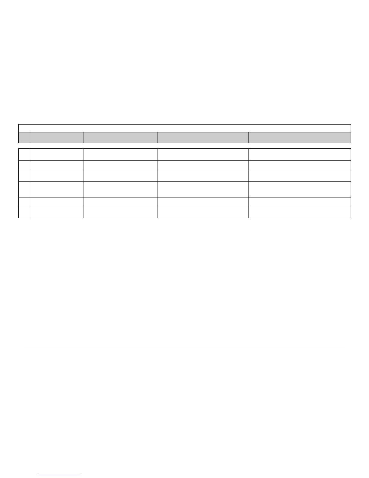
KPT-MOD Parameter List
Customer:____________________________________
Boiler model: _______________ Year of manufacture: ___________
Fuel: ________________________________
Serviceman: ______________________________ Remarks:________________________
Boiler parameters
Unit Min. Max.
efault settingCurrent setting:
Set on: ………
Current setting:
Set on: ………
Current setting:
Set on: ………
1 Boiler temperature, forward flow °C 70 110 85
2 Boiler temperature, return flow °C 65 95 70
3 Residual oxygen, boiler % 4.0 15.0 8.0
4 Boiler temperature, fire box °C 400 999 850
5 Negative pressure, boiler, fire box Pa 20 250 150
6 Underfeed auger cycle: sustain % 1 30 2
7 Underfeed auger cycle: emergency operation % 5 100 30
8 Boiler output for emergency operation % 25 100 75
9 System temperature minimum °C 10 120 75
Underfeed auger
Unit Min. Max.
efault settingCurrent setting:
Set on: ………
Current setting:
Set on: ………
Current setting:
Set on: ………
1 Underfeed pipe temperature °C 50 120 70
2 Underfeed auger filling time Sec. 50 999 350
3 Fire box filling time Sec. 50 999 500
4 Empty running time, metering container, underfeed
auger
Sec. 1 90 25
5 Underfeed auger starting cycle after sustain % 1 100 10
6 Underfeed auger starting cycle after heat up % 1 100 5
7 Underfeed auger, pellet operation On/Off Off
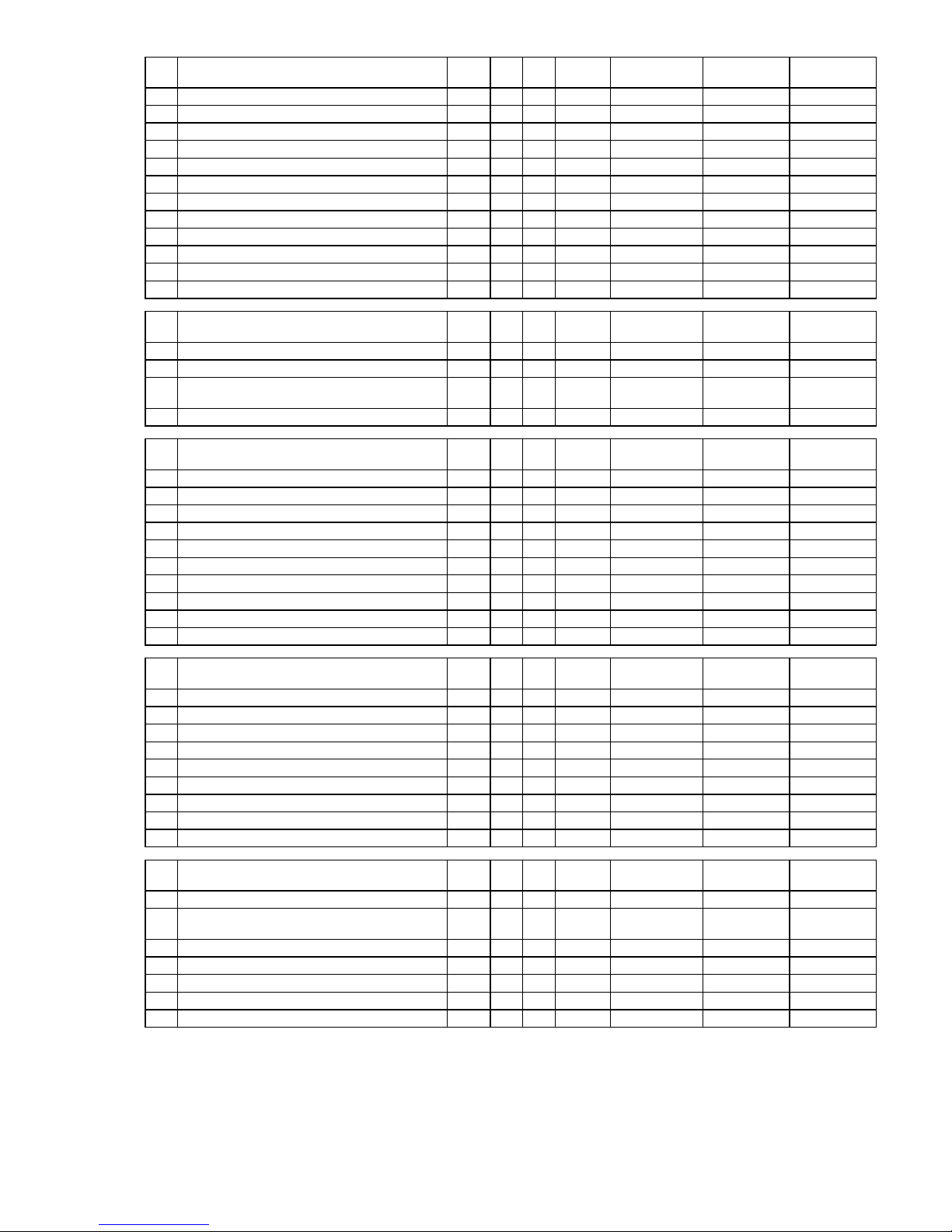
Controller temperature
Unit Min. Max.
efault settingCurrent setting:
Set on: ………
Current setting:
Set on: ………
Current setting:
Set on: ………
1 Boiler forward flow controller, P-factor 0 999 3
2 Boiler forward flow controller, D-factor 0 999 3
3 Boiler forward flow controller, I-factor 0 999 0
4 Boiler return flow controller, P-factor 0 999 10
5 Boiler return flow controller, D-factor 0 999 10
6 Boiler return flow controller, I-factor 0 999 0
7 Hysteresis preservation ON °C 4 20 6
8 Hysteresis preservation OFF °C 0 20 2
9 Hysteresis standby ON °C 4 20 10
10 Hysteresis standby OFF °C 0 20 2
11 Minimum time for standby Min. 0 999 10
12 Temperature for carrying off excess heat °C 50 120 100
Page 29
- Page 2 of 3- 19.10.2007_E
Limit values for furnace firing
Unit Min. Max.
efault settingCurrent setting:
Set on: ………
Current setting:
Set on: ………
Current setting:
Set on: ………
1 Fire box temperature for heat up Æ operation °C 150 500 180
2 Fire box temperature for burn-out Æ off °C 250 500 350
3 Exhaust gas temperature for heat up Æ operation °C 50 150 90
4 Exhaust gas temperature for burn-out Æ off °C 50 150 110
5 Fire box temperature, maximum °C 600 1200 900
6 Residual oxygen, after-running, full load operation % 10.0 20.0 13,5
7 Speed of exhaust fan, sustain % 0 50 18
8 Light barrier delay, ember monitoring system Sec. 0 999 90
9 Residual oxygen, minimum % 3.0 10.0 4.0
10 Residual oxygen delay, heat up Sec. 10 500 30
11 Furnace firing power, wood-powered boiler, minimum % 10 90 20
12 Negative pressure in fire box, sustain Pa 5 200 0
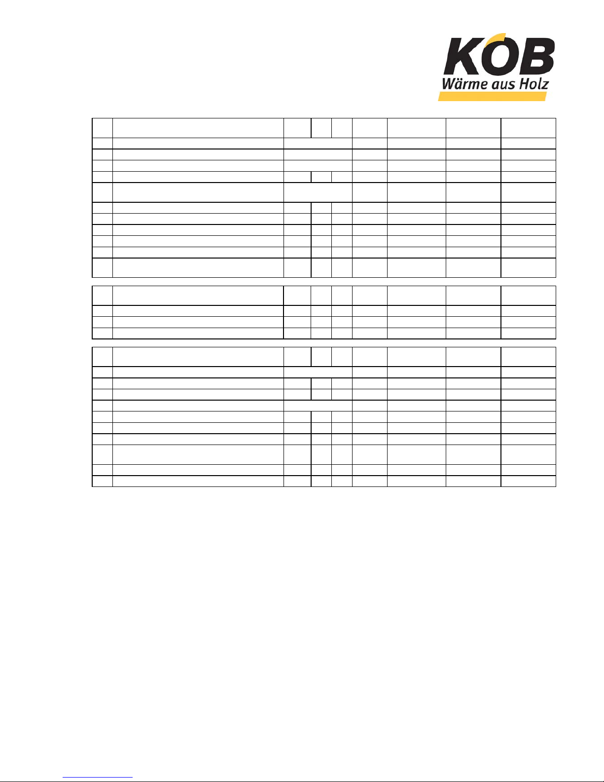
Automatic boiler cleaning syste
m
Unit Min. Max.
efault settingCurrent setting:
Set on: ………
Current setting:
Set on: ………
Current setting:
Set on: ………
1 Pneumatic boiler tubing cleaning system Min. 0 999 40
2 Moving grate pause Sec. 0 999 50
3 Fire box de-ashing system, emergency operation,
pause
Min. 6 999 40
4 Fire box de-ashing system, operating mode
Fuel loading system
Unit Min. Max.
efault settingCurrent setting:
Set on: ………
Current setting:
Set on: ………
Current setting:
Set on: ………
1 Switch-on delay, conveyor auger 1 Sec. 0 50 2
2 Switch-on delay, conveyor auger 2 Sec. 0 50 2
3 Extraction system impulse Sec. 2 30 5
4 Extraction system pause Sec. 0 30 0
5 Extraction system reversing interval Sec. 0 999 240
6 Extraction system direction of advance On/Off Off
7 Switch-on delay for hydraulic system Sec. 0 20 5
8 Light barrier delay for floor conveyor auger Sec. 0 9,9 2.0
9 Floor conveyor auger running time maximum Sec. 20 999 80
10 Hydraulic drive emergency operation impulse Sec. 10 999 90
Controller, furnace firing
Unit Min. Max.
efault settingCurrent setting:
Set on: ………
Current setting:
Set on: ………
Current setting:
Set on: ………
1 Output controller, P-factor 0 999 5
2 Output controller, D-factor 0 999 10
3 Output controller, I-factor 0 999 0
4 Fuel controller, P-factor 0 999 20
5 Fuel controller, D-factor 0 999 20
6 Fuel controller, I-factor 0 999 0
7 Fire box negative pressure controller, P-factor 0 999 20
8 Fire box negative pressure controller, D-factor 0 999 10
9 Fire box negative pressure controller, I-factor 0 999 0
Internal settings
Unit Min. Max.
efault settingCurrent setting:
Set on: ………
Current setting:
Set on: ………
Current setting:
Set on: ………
1 External clearance for wood-powered boiler given On/Off Off
2 External output specification for wood-powered boiler
given
On/Off Off
3 Controller address, serial interface 0 999 110
4 Enter permanent code 0 9999
5 Load factory setting On/Off Off
6 Adjust lambda sensor On/Off Off
7 Boiler forward flow temperature On/Off Off
Page 30
KÖB Holzfeuerungen GmbH
6922 Wolfurt - Flotzbachstr. 33, Österreich – UID-Nr. ATU 61292425
Tel. +43/(0)5574/6770-0 – Fax+43/(0)5574/65707
office@kob.cc – www.koeb-holzfeuerungen.com
Viessmann Group
- Page 3 of 3- 19.10.2007_E
Accumulator management syste
m
Unit Min. Max.
efault settingCurrent setting:
Set on: ………
Current setting:
Set on: ………
Current setting:
Set on: ………
1 Accumulator management system operating mode Auto/Manual/Off Auto
2 Accumulator management system model Köb/QM Köb
3 Accumulator loading to accumulator sensor B28.1 – B28.5 B28.5
4 Accumulator loading to temperature of accumulator °C 30 120 85
5 Start wood-powered boiler temperature fallen short of
at accumulator sensor
B28.1 – B28.5 B28.1
6 Accumulator set-point for atmospheric temp. of + 5°C °C 10 110 80
7 Accumulator set-point for atmospheric temp. of -15°C °C 10 110 85
8 Accumulator temperature set-point, maximum °C 10 110 95
9 Accumulator temperature set-point, minimum °C 10 110 75
10 Accumulator temperature set-point, manual operation °C 10 110 75
11 Maximum correction, temperature of return flow, set-
point
°C 0 30 10
Accumulator management syste
m
Unit Min. Max.
efault settingCurrent setting:
Set on: ………
Current setting:
Set on: ………
Current setting:
Set on: ………
1 Accumulator controller, P-factor 0 999 10
2 Accumulator controller, D-factor 0 999 10
3 Accumulator controller, I-factor 0 999 0
Additional boiler
Unit Min. Max.
efault settingCurrent setting:
Set on: ………
Current setting:
Set on: ………
Current setting:
Set on: ………
1 Additional boiler, operating mode Auto/Manual/Off
2 Forward flow temperature °C 30 120 80
3 Return flow temperature °C 30 120 65
4 Accumulator loading to accumulator sensor B28.1 – B28.5 B28.1
5 Accumulator loading to temperature °C 30 120 80
6 Temperature for connecting additional boiler, delayed °C 50 95 80
7 Switch-on delay for additional boiler Min. 0 90 10
8 Temperature for connecting additional boiler, without
delay
°C 5 50 20
9 Minimum running time for additional boiler Min. 0 90 10
10 After-running of pump for additional boiler Min. 0 20 2
Page 31

Leerseite für Notizen:
Blank page for notes:
Page en blanc pour des notationes:
Page 32

KÖB Holzfeuerungen GmbH, Flotzbachstrasse 33, A-6922 Wolfurt
Tel +43 55 74 / 67 70-0, Fax +43 55 74 / 65 7 07
office@kob.cc, www.koeb-holzfeuerungen.com
Viessmann Group
Verkaufs-Niederlassungen und dazugehörige Service-Außenstellen:
ZENTRALE:
Flotzbachstrasse 33, A-6922 Wolfurt
Tel +43 55 74 / 67 70-0
Fax +43 55 74 / 65 7 07
office@kob.cc
ÖSTERREICH – NORD / OST
A-4906 Eberschwang
Tel +43 77 53 / 32 65
Fax +43 77 53 / 32 65
helmut.fuchsberger@kob.cc
ÖSTERREICH – SÜD / OST
A-8230 Hartberg Greinbach
Tel +43 33 32 / 64 2 12
Fax +43 33 32 / 63 6 16
martin.nussdorfer@kob.cc
VERTRIEBSTOCHTER SCHWEIZ
KÖB Wärmetechnik AG
CH-9430 St. Margrethen
Tel +41 848 / 87 08 10
Fax +41 848 / 87 08 11
SCHWEIZ – ZENTRAL / OST
CH-9243 Jonschwil
Tel +41 71 / 92 38 2 80
Fax +41 71 / 92 38 2 82
josef.meier@kob.cc
SCHWEIZ – ZENTRAL / NORD
CH-4704 Niederbipp
Tel +41 32 / 63 30 7 10
Fax +41 32 / 63 30 7 11
adrian.rippstein@kob.cc
DEUTSCHLAND – SÜD / WEST
D-72639 Neuffen
Tel +49 70 25 / 80 42
Fax +49 70 25 / 83 69 6
gerald.sieler@kob.cc
DEUTSCHLAND – SÜD / MITTE
D-89278 Nersingen
Tel +49 73 08 / 91 00 10
Fax +49 73 08 / 52 66
hans.amann@kob.cc
DEUTSCHLAND – SÜD / OST
D-82549 Königsdorf
Tel +49 8179 / 92 95 65
Fax +49 8179 / 92 95 66
roland.metzner@kob.cc
●
DEUTSCHLAND – NORD / WEST
D-44579 Castrop-Rauxel
Tel +49 23 05 / 7 38 91
Fax +49 23 05 / 8 37 62
koeb-nw@t-online.de
●
DEUTSCHLAND – MITTE / OST
D-89278 Nersingen
Tel +49 7308 / 811347
Fax +49 7308 / 811387
tobias.amann@kob.cc
DEUTSCHLAND – NORD / OST
D-16727 Oberkrämer/ OT Eichstätt
Tel +49 33 04 / 31 70 8
Fax +49 33 04 / 31 70 8
wolfgang.ratzka@kob.cc
KOB Italia S.r.l.
I-36063 Marostica
Tel +39 0424 8 10 50
Fax +39 0424 47 34 45
italia@kob.cc
LUXEMBOURG
D-72639 Neuffen
Tel +49 70 25 / 80 42
Fax +49 70 25 / 83 69 6
gerald.sieler@kob.cc
FRANCE
F-04300 Forcalquier
Tel. +33 492 / 73 10 80
Fax: +33 492 / 73 10 80
servicefrance@kob.cc
●
FRANCE - OVEST
F-79160 Coulonges/L‘Autize
Tel. +33 549 / 06 06 60
Fax +33 549 / 06 00 60
energie79@wanadoo.fr
1 Serviceleitstelle Zentrale Wolfurt
KÖB Holzfeuerungen GmbH, Flotzbachstrasse 33, A-6922 Wolfurt
Tel +43 55 74 / 67 70-0, Fax +43 55 74 / 65 7 07, office@kob.cc
2 Serviceleitstelle für Italien
KOB Italia S.r.l., I-36063 Marostica
Tel +39 0424 78 10 50, Fax +39 0424 47 34 45, italia@kob.cc
3 Serviceleitstelle für Frankreich
F-04300 Forcalquier, Tel. +33 492 / 73 10 80, Fax: +33 492 / 73 10 80
servicefrance@kob.cc
SERVICE – EST: Electromatic – sarl, F-67550 Vendenheim
Tel +33 607 / 64 06 31, Fax +33 38 / 86 93 7 60. servicefrance@kob.cc
● Verkaufsorganisation mit eigenem Service
●
NORGE
AS Morgan
N-3933 Porsgrunn
Tel. +47 355 / 693 00
Fax: +47 355 / 693 15
fyk@asmorgan.no
●
NEDERLAND / BELGIE
LVB Wood Drying + Energy Systems BV
NL-4141 BE Leerdam
Tel. +31 345 / 61 97 88
Fax: +31 345 / 61 69 05
office@lvb-wood.nl
●
UNITED KINGDOM
3G Energi
UK – TD5 7BH, Kelso
Tel. +44 1573 22 91 98
Fax. +44 870 706 2555
enquiries@3genergi.co.uk
●
KÖB SVERIGE AB
S-65350 Karlstad
Tel. +46 54 53 69 87
Fax. +46 54 53 18 43
bengt.nilsson@fbp.se
●
IRLAND
Clearpower Ltd.
Dublin 2
Tel. +35 31 66 90 979
Fax. + 35 31 66 90 978
info@clearpower.ie
●
CANADA
Fink Machine Inc.
Enderby B.C
Tel. (001) 250 83 80 077
Fax. (001) 250 83 800 68
fink@jetstream.net
1
1
1
1
1
1
1
1
1
1
2
3
1
 Loading...