

Page 1
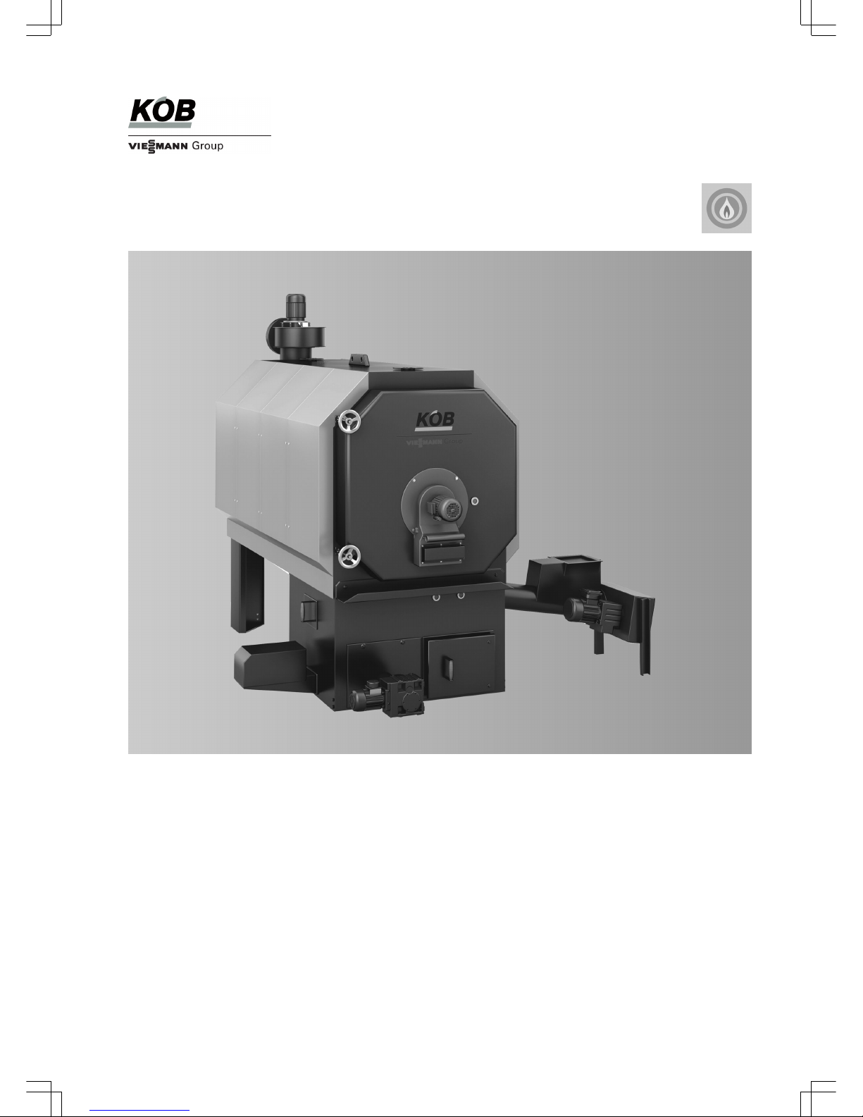
PYROT
Wood boiler 100 to 540 kW
PYROT ROTATION COMBUSTION
SYSTEM
Fully automatic wood boiler
for the combustion of dry woodchips and pellets
5822 516 GB 05/2010
Technical guide
Page 2

Index
1. Principles of wood combustion 1. 1 Principles of pellet combustion for generating heat .................................................... 6
■ What are wood pellets? .......................................................................................... 6
■ Fuel requirements ................................................................................................... 6
■ Forms of delivery .................................................................................................... 6
1. 2 Principles of woodchip combustion for generating heat ............................................. 6
■ What are woodchips? ............................................................................................. 6
■ Fuel requirements ................................................................................................... 6
1. 3 Minimum wood fuel requirements ............................................................................... 7
■ Content ................................................................................................................... 7
■ Non-wood biomass fuels ......................................................................................... 7
■ Wood fuel regulations and standards ..................................................................... 7
2. PYROT rotation combustion 2. 1 Product description ..................................................................................................... 8
■ Benefits at a glance ................................................................................................ 8
■ Delivered condition ................................................................................................. 8
2. 2 Specification ............................................................................................................... 9
■ Specification ............................................................................................................ 9
3. Control unit 3. 1 Specification for ECOTRONIC .................................................................................... 14
■ Structure and function ............................................................................................. 14
3. 2 Accessories for Ecotronic ........................................................................................... 15
■ Modules and data cables ........................................................................................ 15
■ Optional combinations ............................................................................................ 15
■ Overview: Possible Ecotronic controllers ................................................................ 15
■ Controller, central heating ....................................................................................... 16
■ Controller, adjacent building ................................................................................... 16
■ Room controller QAA 35 ......................................................................................... 16
■ Safety thermostat RAK-TW.1000B ......................................................................... 17
■ Controller, long-distance line .................................................................................. 17
■ Controller, space heater .......................................................................................... 18
■ Controller, DHW cylinder B1 ................................................................................... 18
■ Controller, DHW cylinder B2 ................................................................................... 19
■ Controller, DHW circulation ..................................................................................... 19
■ Controller, solar DHW cylinder ................................................................................ 20
■ Controller, solar/DHW and central heating ............................................................. 20
3. 3 Accessories for ECOTRONIC output management .................................................... 22
■ Cylinder management 3 sensors ............................................................................ 22
■ Cylinder management 5 sensors ........................................................................... 22
■ External requirement ON/OFF ................................................................................ 22
■ Operating message potential-free ........................................................................... 22
■ Output signals 0-10 V ............................................................................................. 22
3. 4 Accessories for ECOTRONIC remote transfer ........................................................... 23
■ Fault message device, analogue with battery ......................................................... 23
■ Export of operating data .......................................................................................... 23
■ Visualisation Pyrot - internal ................................................................................... 23
■ Visualisation, additional functions ........................................................................... 23
■ Data cable to visualisation - internal ....................................................................... 23
■ Visualisation, externally via modem (connected with cable) ................................... 24
3. 5 Mastercontrol for two-boiler systems .......................................................................... 25
■ Information on the Mastercontrol ............................................................................ 25
■ Standard delivery .................................................................................................... 25
■ Visualisation with touch-screen ............................................................................... 25
■ Schematic diagram ................................................................................................. 26
3. 6 Accessories for Mastercontrol .................................................................................... 27
■ Heat meter signal .................................................................................................... 27
■ Requirement, additional heat source KP0 .............................................................. 27
■ Requirement, additional heat source KP1 .............................................................. 27
■ Fault message device, analogue with battery ......................................................... 28
■ Export of operating data .......................................................................................... 28
4. Heating water buffer cylinder 4. 1 Specification, buffer cylinder ....................................................................................... 29
■ Buffer cylinder HPM ................................................................................................ 29
■ Buffer cylinder WDW 2000 l .................................................................................... 30
■ Buffer cylinder WDW 2900 l .................................................................................... 31
Index
2
PYROT
5822 516 GB
Page 3

5. Installation accessories 5. 1 Boiler safety equipment .............................................................................................. 32
■ Thermally activated safety valve 100 °C ................................................................. 32
■ Thermally activated extinguishing valve ½”, 50-90 °C ............................................ 32
■ Supply screw conveyor two-level ............................................................................ 32
■ Insulation, flue gas recirculation line ....................................................................... 32
5. 2 Accessories, heat distribution ..................................................................................... 33
■ Motor three-way valve for Pyrot 100 kW ................................................................. 33
■ Motor three-way valve for Pyrot 150-540 kW .......................................................... 33
■ Pumps ..................................................................................................................... 33
5. 3 Accessories, flue system ............................................................................................ 34
■ Flue gas dust extractor ........................................................................................... 34
■ Metal mesh filter ...................................................................................................... 36
■ Cleaning, pneumatic ............................................................................................... 37
■ Price reduction net compressed air on site ............................................................ 38
5. 4 Accessories, ash removal ........................................................................................... 39
■ External container ................................................................................................... 39
■ Ash removal into the base container ....................................................................... 41
6. Design information 6. 1 System design ............................................................................................................ 41
■ Selection of rated output ......................................................................................... 41
■ Flow temperatures .................................................................................................. 41
■ Safety temperatures ................................................................................................ 42
6. 2 Delivery ....................................................................................................................... 42
6. 3 Handling ...................................................................................................................... 42
6. 4 Siting ........................................................................................................................... 42
■ Requirements for boiler room ................................................................................. 42
■ Requirements of the Muster-Feuerungsverordnung [Germany] ............................. 43
■ Combustion air supply ............................................................................................ 43
■ Safety precautions .................................................................................................. 44
■ Minimum clearances ............................................................................................... 44
6. 5 Water connection ........................................................................................................ 45
■ Heating connections ............................................................................................... 45
■ Boiler circuit and shunt pumps ................................................................................ 45
■ Safety equipment to DIN EN 12828 ........................................................................ 45
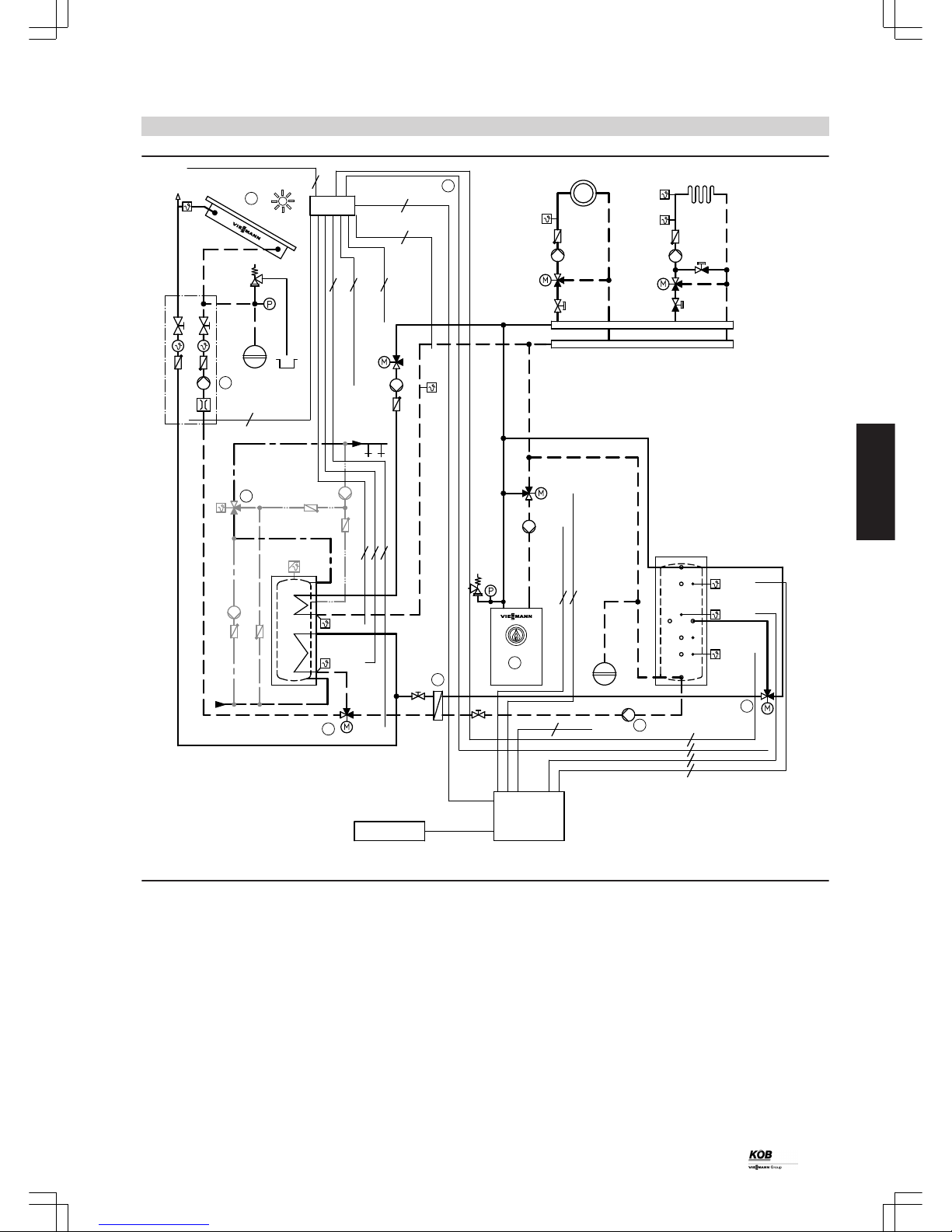
■ System example ..................................................................................................... 45
6. 6 Electrical installation ................................................................................................... 47
■ Positioning of the programming module and control panel ..................................... 47
6. 7 Safety equipment ........................................................................................................ 47
■ Expansion ............................................................................................................... 47
■ Extinguishing facilities ............................................................................................. 47
■ Extinguishing water container ................................................................................. 48
■ Extinguishing facility with cold water supply ........................................................... 48
■ Prevention of combustion chamber overfilling ........................................................ 49
■ Reignition protection (RZS) ..................................................................................... 49
■ Back burning protection, fuel supply (RSE) ............................................................ 49
■ Shut-off gate valve .................................................................................................. 49
■ Rotary lock valve ..................................................................................................... 49
■ Low water indicator ................................................................................................. 49
■ Maximum pressure limiter ....................................................................................... 49
■ Minimum pressure limiter ........................................................................................ 49
■ Safety valve ............................................................................................................ 49
■ Expansion vessel .................................................................................................... 49
6. 8 Fire protection ............................................................................................................. 50
■ Fire safety, fuel store .............................................................................................. 50
6. 9 Commissioning ........................................................................................................... 50
■ Fuel for commissioning ........................................................................................... 50
■ Filling the heating system ....................................................................................... 50
6.10 Fuels ........................................................................................................................... 50
■ Suitable fuels .......................................................................................................... 50
6.11 Fuel discharge by means of screw conveyor .............................................................. 51
■ Discharge screw conveyor, pellet, D = 120 mm ..................................................... 51
■ Drive, discharge screw conveyor, pellets ................................................................ 52
6.12 Fuel discharge by means of agitators ......................................................................... 53
■ Spring core discharge AF ....................................................................................... 53
■ Discharge screw conveyor AF to spring core discharge ......................................... 55
■ Horizontal discharge AH ......................................................................................... 55
■ Discharge screw conveyor AH for horizontal discharge ......................................... 58
■ Protective panel AH for bunker ............................................................................... 58
■ Cover panel AH for pellets ...................................................................................... 58
Index
(cont.)
PYROT
3
5822 516 GB
Page 4

6.13 Fuel discharge by means of funnel discharge ............................................................ 59
■ Funnel discharge .................................................................................................... 59
■ Additional outlet flange ............................................................................................ 60
■ Funnel, large .......................................................................................................... 60
6.14 Fuel discharge by means of push floor (sizing) .......................................................... 60
■ Number and length of the pushrods with a maximum dumping height ................... 60
■ Specification for the pushrod drives ........................................................................ 61
■ Forces on the building ............................................................................................. 61
■ Slot discharge, for pulling ........................................................................................ 62
■ Centre discharge ..................................................................................................... 63
■ Slot discharge with fill function ................................................................................ 65
6.15 Fuel discharge by means of push floor (accessory) ................................................... 67
■ Pushrod drive, individual ......................................................................................... 67
■ Weld base, pushrod drive, individual ...................................................................... 67
■ Pushrod drive, twin ................................................................................................ 67
■ Weld base, pushrod drive, twin ............................................................................... 67
■ Weld base, bunker .................................................................................................. 67
■ Pushrod ................................................................................................................... 68
■ Hydraulic drive, AS individual ................................................................................. 68
■ Hydraulic drive, AS twin .......................................................................................... 69
■ Push floor screw conveyor D = 190 mm ................................................................. 69
■ Push floor screw conveyor D = 250 mm ................................................................. 69
■ Drive, push floor screw conveyor, standard ............................................................ 70
■ Drive, push floor screw conveyor, higher-power ..................................................... 70
■ Cover, push floor screw conveyor ........................................................................... 70
6.16 Charging the boiler with fuel ....................................................................................... 70
■ Trough screw conveyor ........................................................................................... 70
■ Drive, trough screw conveyor, standard ................................................................. 71
■ Pipe screw conveyor ............................................................................................... 71
■ Drive, pipe screw conveyor, pellet .......................................................................... 73
■ Drive, pipe screw conveyor, standard ..................................................................... 74
■ Drive, pipe screw conveyor, high-power ................................................................. 74
6.17 Fuel storage in on-site pellet store (sizing) ................................................................. 74
■ Sizing the pellet storage room ................................................................................ 74
■ Pellet storage room design and required system components ............................... 75
■ Additional safety instructions for pellet stores ......................................................... 76
■ Protective boards with Z brackets ........................................................................... 76
■ Fill connector and return connector ........................................................................ 76
6.18 Fuel storage in on-site pellet store (accessories) ....................................................... 79
■ Deflector 1.42 x 1.25 m ........................................................................................... 79
■ Fill connector and return connector, straight ........................................................... 79
■ Fill connector and return connector, 45° ................................................................. 79
■ Extension of fill connector and return connector ..................................................... 80
6.19 Fuel storage in on-site bunker (accessories) .............................................................. 80
■ Silo cover, manual FDM 2.9/1.3 m .......................................................................... 80
■ Bunker cover hydraulic FDH ................................................................................... 81
■ Fall protection grille 120 for FDH ........................................................................... 83
■ Fall protection grille 200 for FDH ........................................................................... 83
■ Bunker cover, movable FDB ................................................................................... 83
■ Fall protection grille, 120 for FDB ........................................................................... 85
■ Fall protection grille, 200 for FDB .......................................................................... 85
■ Shaker motor for fall protection grille ...................................................................... 85
■ Hydraulic drive, bunker charging cover, ASH ......................................................... 85
■ Cover drives for hydraulic drive, ASH .................................................................... 86
■ Silo filling screw conveyor FS 300 .......................................................................... 86
■ Drive, silo filling screw conveyor ............................................................................ 86
6.20 Back burning protection .............................................................................................. 87
■ Rotary lock valve ..................................................................................................... 87
■ Shut-off gate valve MA 220 ..................................................................................... 88
■ Downpipe L = 1.0 m ................................................................................................ 88
■ Special adaptor ....................................................................................................... 88
6.21 Connection on the flue gas side ................................................................................. 89
■ Chimney .................................................................................................................. 89
■ Flue pipe (sizing) ..................................................................................................... 89
■ Flue gas routing (accessories) ................................................................................ 89
6.22 Sound insulation ......................................................................................................... 90
■ Braces ..................................................................................................................... 90
7. Appendix 7. 1 Sizing the expansion vessel ....................................................................................... 90
■ Selection example ................................................................................................... 91
Index
(cont.)
4
PYROT
5822 516 GB
Page 5

7. 2 General information regarding low pressure hot water boilers with safety temperatures
of up to 110 ºC ............................................................................................................ 91
7. 3 Pipe connections ........................................................................................................ 91
7. 4 Electrical installation ................................................................................................... 92
7. 5 Operating instructions ................................................................................................. 92
7. 6 Flue system ................................................................................................................ 92
7. 7 Checks as part of the Building Regulations approval process .................................... 92
8. Keyword index .............................................................................................................................................. 93
Index
(cont.)
PYROT
5
5822 516 GB
Page 6

1.1 Principles of pellet combustion for generating heat
What are wood pellets?
Wood pellets are made from 100% natural wood remnants. This raw material is waste matter created by the wood industry in large volumes
through planing or sawing. Wood remnants are compressed under high pressure and formed into pellets, i.e. pressed into a cylindrical shape.
The raw material is stored and transported in completely dry conditions. The system user should also ensure completely dry storage conditions.
Optimum and effective combustion can only be ensured under these conditions.
Fuel requirements
For combustion in the PYROT, use pellets with a diameter of 6 mm, a
length from 5 to 30 mm (20 % up to 45 mm) with a maximum residual
moisture content of 10 %.
The wood pellets used for combustion in the PYROT must correspond
to the requirements of DINplus or ÖNORM M 7135.
Requirements DINplus ÖNORM
M 7135
Abrasion resistance %
≤ 2.3 ≤ 2.3
Raw density
kg/dm
3
≥ 1.12 ≥ 1.12
Water content %
≤ 10 ≤ 10
Ash content %
≤ 0.5 ≤ 0.5
Net calorific value MJ/kg
≥ 18 ≥ 18
kWh/kg
≥ 5 ≥ 5
Sulphur content %
≤ 0.04 ≤ 0.04
Chlorine content %
≤ 0.02 ≤ 0.02
Nitrogen content %
≤ 0.3 ≤ 0.3
Compression additive %
≤ 2 ≤ 2
Ext. production control yes –
Quality characteristics
High quality pellets:
■ Smooth shiny surface
■ Uniform length
■ Low proportion of dust
■ Sink in water
Low quality pellets:
■ Cracked rough surface
■ Severely varying length
■ High proportion of dust
■ Float in water
Forms of delivery
In their loose form, pellets are transported by silo tanker and pumped
into the storage room via a hose system.
Careful handling of pellets enables a low proportion of dust, troublefree boiler charging and a constant wood boiler output.
1.2 Principles of woodchip combustion for generating heat
What are woodchips?
Woodchips are made from 100 % natural wood from forests and plantations. This raw material comes in the form of trunks or branches. The
wood is then processed with high speed cutting tools in accordance with ÖNORM M 7133.
The raw material is stored and transported in completely dry conditions. The system user should also ensure completely dry storage conditions.
Optimum and effective combustion can only be ensured under these conditions.
Fuel requirements
For combustion in the PYROT, use woodchips with a maximum coarse
percentage of 20 %, a maximum cross-section of 5 cm² and a maximum length of 12 cm (5 % with max. 16 cm).
Bulk density S (kg/m³, water content W (%), size G (mm) as per ÖNORM M 7133
S 200 W20 G30/50 Soft natural woodchips from forests
S 250 W20 to W35 G30/50 Soft natural woodchips from forests
S 300 W20 to W35 G30/50 Soft/hard natural woodchips from forests
S 300 W35 to W50 G30/50 Soft natural woodchips from forests
S 350 W20 to W35 G30/50 Hard natural woodchips from forests
Quality characteristics
High quality woodchips:
■ As per ÖNORM M 7133
■ Size G30 or G50
■ Max. 5 % outliers
■ Smooth surfaces
Low quality woodchips:
■ Frayed surface
■ More than 5 % outliers
■ Coarse percentage higher than 20 %
■ Greater than G30 or G50
Principles of wood combustion
6
PYROT
1
5822 516 GB
Page 7

1.3 Minimum wood fuel requirements
Content
When procuring wood for combustion, it is important to ensure that
foreign matter (e.g. stones, metal parts, brick fragments, plastics, etc.)
is avoided. This changes the composition of the fuel and therefore the
critical parameters of the combustion process.
The values must not exceed or fall below the following limits (per kg of
dry fuel) for the non-combustible content (ash at an analysis temperature of 815 °C):
Limit Comparison with natural wood from forests
Chlorine Cl mg/kg max. 300 10
Sulphur S mg/kg max. 1000 120
Total Cl, S mg/kg max. 1000 130
Ash content total g/kg max. 15.0 5.0
Alkali oxides in the ash (K2O and Na2O) g/kg max. 1.0 0.35
SB start of ash sintering °C min. 1000 approx. 1200
A consequence of exceeding the above limits is a shortened service
life of the combustion chamber and wood boiler. This also means that
maintenance work is increased and service intervals are reduced.
The proportion of dust-like and fine-grain materials should also be
minimised (in accordance with ÖNORM M 7133).
Non-wood biomass fuels
Non-wood biomass fuels, such as needles, leaves, grain, straw, husks,
fruit kernels, etc., are generally unsuitable as a fuel for trouble-free
operation and are therefore not permissible.
In some cases, the fuel properties (essential composition, ash sintering point, etc.) differ considerably from those of wood. Combustion in
a Pyrot may lead to impairment of the combustion characteristics and
to greater stress on the fireclay lining and the heat exchanger surfaces.
Warranty claims can therefore only be asserted when using permissible fuels.
Wood fuel regulations and standards
Germany Revised first version of BImSchV dated 22.03.2010
Austria FAV dated 18.11.1997 "Ordinance for Combustion Systems" § 3.(1) 3. Solid fuels
Switzerland Clean air regulations LRV dated 16.12.1985 (as of 28.03.2000)
ÖNORM M 7133 Woodchips for energy purposes (1998)
EN 303-5 Boilers for solid fuels, table 8 "Test fuels"
CEN/TS 14961 Solid biofuels
Principles of wood combustion
(cont.)
PYROT
7
5822 516 GB
1
Page 8

2.1 Product description
A
Controlled secondary air with rotary fan
B
Rotary combustion chamber
C
Boiler heat exchanger
D
Safety heat exchanger
E
Flue gas fan with Lambda probe and temperature sensor
F
Pneumatic cleaning
G
Flue gas recirculation, controllable
H
Regulated primary air
K
Ignition fan
L
Fully moving grate
M
Ash removal
With its patented rotation combustion, the Pyrot wood boiler represents state of the art wood combustion. A supply screw conveyor continuously guides the wood fuel onto a moving grate on which the fuel
combustion takes place. Continuous gasification takes place under air
starvation. A rotary fan is used to mix rising combustion gases with the
secondary air displaced in a rotary motion. This ensures thorough
mixing with the combustion gases.
Clean and efficient combustion
The proven combustion technology in the Pyrot achieves similar emissions values to those of a modern gas combustion system and keeps
the release of CO, NOx and dust particles to a minimum, subject to
fuel type. The combination of combustion technology and digital modulating output control enables efficiency levels of up to 92 %.
Mobile containerised heating centre
Pyrot wood boilers are available as containerised complete solutions
for uses where there are no boiler houses available or where the onsite building costs have to be reduced to a minimum. This complete
solution incorporates the pre-assembled wood boiler inside a special
container with all ancillary devices. In addition to finished container
solutions, individual versions can be specially matched to your
needs.
Benefits at a glance
■ High efficiency levels (up to 92 %) and low emissions through regulated primary and secondary air supply and low particle combustion
■ Two-pass heat exchanger and modulating output control (4:1 control
range)
■ Automatic ignition prevents having to maintain the incandescent bed
and saves fuel
■ Easy service thanks to fully automatic ash removal, optional pneumatic cleaning system and flue gas dust extractor
■ Highly developed safety devices ensure a safe and reliable operation
■ Individual planning of your system by our team of experts
■ Available as a complete ready-to-use containerised solution
Delivered condition
Pre-assembled steel boiler for wood pellets and woodchips according
to DINplus and ÖNORM M 7135.
Combustion chamber door, ash doors, ash boxes, cleaning device.
1 supply screw conveyor with separating barrier, incl. extinguishing
valve with dirt trap
1 flue gas fan
1 extinguishing water container with holder
1 automatic ignition system
1 set displacer rods
1 recirculation gas device
1 secondary air device (draught stabiliser); for on-site installation in the
flue pipe
Sensors:
■ Infrared light barrier for level monitoring, separating barrier, supply
screw conveyor
■ Safety limit switch on inspection cover of supply screw conveyor
■ Contact sensor Pt100 at the supply screw conveyor
■ Infrared light barriers for level monitoring of the fuel in the combustion chamber
■ Zirconium dioxide probe with measured value transducer
■ Flue gas temperature sensor PT-100
■ Return temperature sensor KTY
■ Boiler water temperature sensor KTY
■ High limit safety cut-out (STB)
■ Temperature sensor, rotary fan
■ Sensor KTY with sensor well
PYROT rotation combustion
8
PYROT
2
5822 516 GB
Page 9

2.2 Specification
Specification
Trade name Pyrot rotation combustion
Rated output kW 100 150 220 300 400 540
Part no.: 7423 656 7423 657 7423 658 7423 659 7423 660 7423 661
Output data
Rated output kW 100 150 220 300 400 540
Continuous output
*1
kW 90 135 200 270 360 480
Minimum output Q
min
*2
kW 30 45 60 80 100 140
Heating data
– Content on hot gas side l 325 374 744 883 1340 1613
– Permissible shutdown temperature of
the high limit safety cut-out.
°C 100 100 100 100 100 100
– Minimum return temperature °C 65 65 65 65 65 65
– Grate ash container capacity l 26 32 45 55 75 91
– Ash container capacity, flue gas dust
extractor
l 90 90 90 90 90 90
Boiler water content l 395 432 794 903 1326 1510
Pressure drop on the DHW side mbar 38 33 76 42 29 56
Permiss. operating pressure
Test pressure bar 5 5 5 5 5 5
Maximum operating pressure bar 3 3 3 3 3 3
Heating surface
m
2
8.28 10.78 16.4 20.72 28.76 39.36
CE designation CE CE CE CE CE CE
Boiler class to DIN EN 303-5 3 3 3 3 3 3
Overall dimensions
Total length (with door open) mm 2870 3120 3424 3780 4004 4232
Total width mm 1050 1050 1330 1330 1570 1570
Total width (with supply screw conveyor) mm 2070 2180 2350 2350 2590 2590
Total height mm 1825 1825 2084 2084 2422 2492
Total height (with induced draught fan) mm 2236 2266 2526 2534 2832 2902
Total weight
–
Boiler
*3
kg 1278 1451 2119 2441 3235 3671
– Combustion block kg 432 477 581 641 778 937
– Displacer rods kg 68 87 141 163 220 289
– Flue gas fan kg 37 40 40 45 62 62
– Supply screw conveyor kg 143 143 143 143 143 149
–
Total dry weight
*4
kg 1958 2198 3024 3433 4438 5108
– Total wet weight kg 2353 2630 3818 4336 5764 6618
Max. power consumption
– During ignition W 1600 1600 1600 1600 1600 1600
– Electrical connections (total) W 2670 2670 2850 3600 3980 3630
– Supply screw conveyor W 370 370 550 1100 1100 750
– Rotary fan W 120 120 120 120 120 120
– Flue gas fan W 550 550 550 750 1100 1100
– Grate drive W 30 30 30 30 60 60
– Electrical power consumption with QNW 850 1032 1108 1521 1868 1753
– Electrical power consumption with Q
min
W 280 355 369 434 480 460
Boiler connections
Boiler flow and return G 2 fem. 2 fem. DN80 PN6 DN80 PN6 DN100 PN6 DN100 PN6
Extinguishing water connection R ¾ ¾ ¾ ¾ ¾ ¾
Boiler drain valve Rp 1 ½ 1 ½ 1 ½ 1 ½ 1 ½ 1 ½
Safety heat exchanger 2x R ½ ½ ½ ½ ½ ½
Sensor well for TS Rp ½ ½ ½ ½ ½ ½
*1
Levelled output as base load boiler in continuous operation with pneumatic cleaning
*2
Q ≥ Q
min
: Output operation modulating control (variable output control)
Q ≤ Q
min
: Low load with ON Q
min
/ OFF (Stop and Go operation)
*3
Incl. door and refractory concrete lining
*4
Incl. displacer rods
PYROT rotation combustion
(cont.)
PYROT
9
5822 516 GB
2
Page 10

Trade name Pyrot rotation combustion
Rated output kW 100 150 220 300 400 540
Part no.: 7423 656 7423 657 7423 658 7423 659 7423 660 7423 661
Flue gas
*5
Average temperature (gross*6)
–
Average flue gas temperature with Q
N
*7
°C 160 160 160 160 160 160
– Average flue gas temperature with Q
min
°C 130 130 130 130 130 130
Mass flow rate
– QN; W5; O2 6 % g/s 53.6 80.4 117.9 160.8 214.4 289.44
– Q
W35
; W35; O2 8 % g/s 71.3 106.9 156.9 213.9 285.2 385.1
Flow rate
– QN; W5; O2 6 %; 150 °C
m3/s
0.06 0.09 0.14 0.19 0.25 0.35
– Q
W35
; W35; O2 8 %; 150 °C
m3/s
0.08 0.12 0.19 0.25 0.34 0.46
CO2 content in the flue gas % 15 15 15 15 15 15
Flue outlet 7 mm 200 250 250 300 350 350
Required draught Pa 0 0 0 0 0 0
Efficiency
– At full load % 90 90 90 90 90 90
– At partial load % 92 92 92 92 92 92
*5
Values for calculating the size of the flue system to DIN EN 13384, based on 12.0 % CO
2
*6
Actual flue gas temperature as average gross value as per EN 304 at 20 °C combustion air temperature
*7
Flue gas temperature: Increase possible by removing the displacer rods (QN+ 30 °C; Q
min
+ 10 °C)
PYROT rotation combustion
(cont.)
10
PYROT
2
5822 516 GB
Page 11
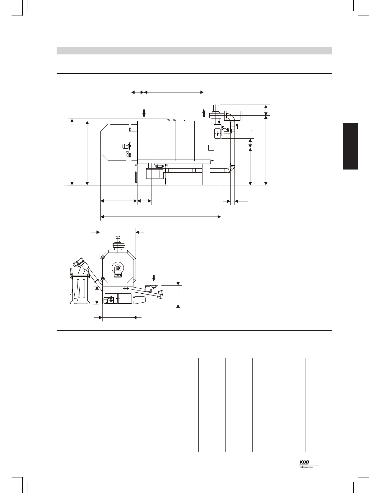
Dimensions
44.84 mm
7.01 mm
9.04 mm23.53 mm
77.57 mm
42.74 mm
24.11 mm5.96 mm
41.51 mm
8.22 mm38.51 mm
h
l k
m
n
a
b
c
d
f
e
KR
KV
2.67 mm
g
23.03 mm
19.57 mm
11.60 mm
r
p
q.
12.05 mm
o
KR Boiler return
KV Boiler flow
Dimensions
Rated output kW 100 150 220 300 400 540
a mm 392 392 406 406 466 466
b mm 1291 1541 1525 1875 1800 2030
c mm 345 358 358 352 375 375
d mm 1891 1908 2168 2182 2457 2527
e mm 303 303 316 316 319 319
f mm 1093 1093 1179 1179 1219 1219
g mm DN 80 DN 80 DN 80 DN 125 DN 125 DN 125
h mm 2870 3120 3424 3780 4004 4232
k mm 320 370 370 440 480 548
l mm 870 870 1150 1150 1390 1390
m mm 1765 1765 2024 2024 2262 2262
n mm 1825 1825 2084 2084 2422 2492
o mm 700 700 700 700 700 742
p mm 870 870 1150 1150 1390 1390
q mm 673 673 673 673 673 750
r mm 1050 1050 1330 1330 1570 1570
PYROT rotation combustion
(cont.)
PYROT
11
5822 516 GB
2
Page 12
54,17 mm6,68 mm
5,30 mm
70,02 mm
4,52 mm
K
A B C E F G
H
263
220
b
a
330
D
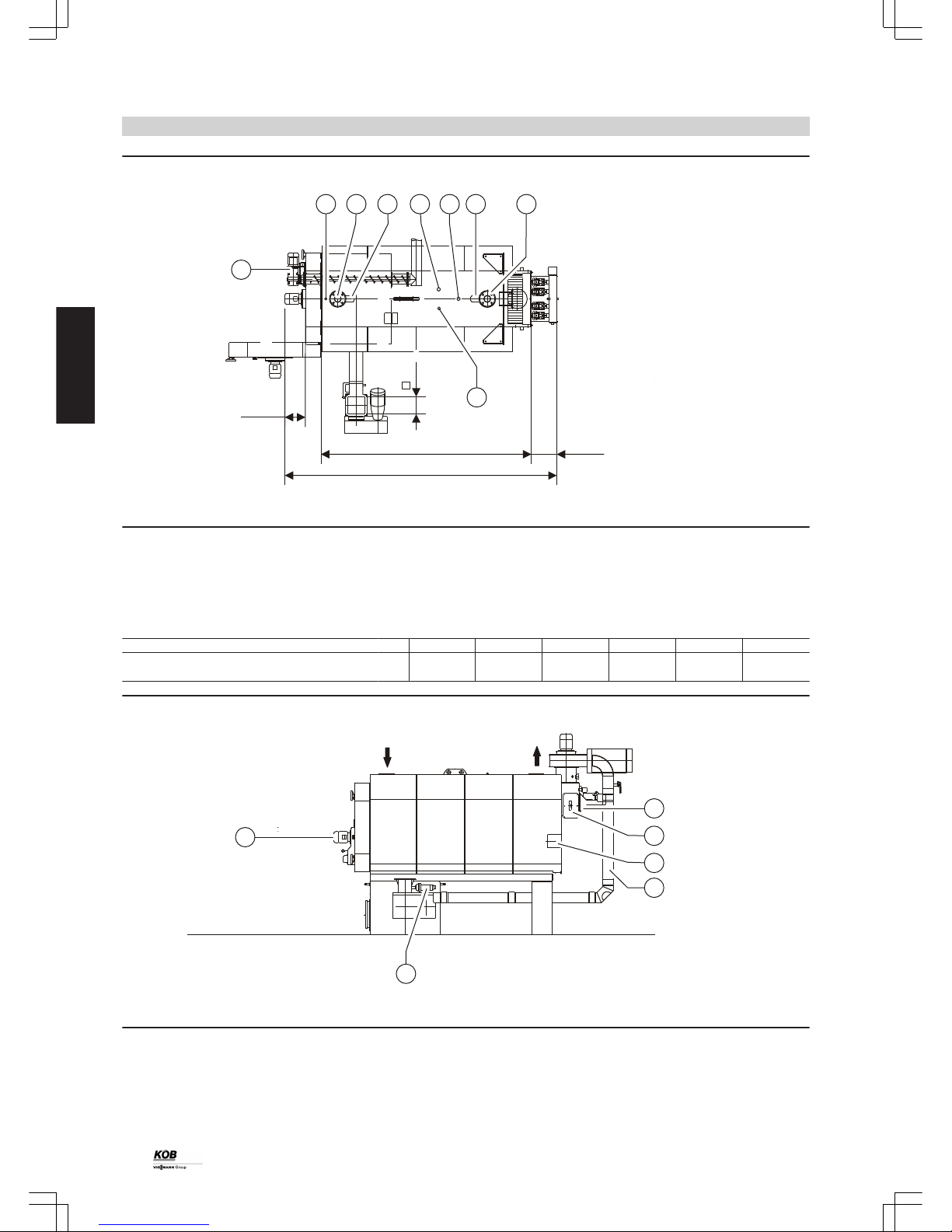
A
Sensor well for TS
B
Boiler return
C
Return temperature sensor
D
Safety heat exchanger
E
High limit safety cut-out (STB)
F
Boiler water temperature sensor
G
Boiler flow
H
Safety heat exchanger
K
Ash removal, combustion block
Dimensions
Rated output kW 100 150 220 300 400 540
a mm 2785 3035 3059 3415 3457 3685
b mm 2000 2250 2274 2630 2614 2842
KR
KV
F
A
E
D
C
B
A
Pneumatic cleaning
B
Cleaning cover, flue gas collector
C
Flange for burner trolley; standard version: Cover with sight
glass
D
Recirculation gas line, line routing variable
E
Ignition unit
F
Rotary fan
KV Boiler flow
KR Boiler return
PYROT rotation combustion
(cont.)
12
PYROT
2
5822 516 GB
Page 13

A B
K
FH
E
D
C
G
A
Flue gas fan
B
Boiler door with rotary fan
C
Extinguishing water connection
D
Supply screw conveyor
E
Drive, infeed grate
F
Ash doors of the grate ash container (2 pce)
G
Drive, ash removal
H
Maintenance cover, combustion block
K
Ash removal, rising screw conveyor
PYROT rotation combustion
(cont.)
PYROT
13
5822 516 GB
2
Page 14

3.1 Specification for ECOTRONIC
The Ecotronic system control unit is a decentralised microprocessor
system (CAN BUS). To control the boiler system, the Ecotronic comprises a module (PCB) integrated into the control panel, and the programming module. Controller modules can be added to the Ecotronic
(modular structure). It is therefore possible to extend operation individually according to customer requirements.
Structure and function
Modular structure
The Ecotronic system control unit is a decentralised microprocessor
system (CAN BUS). To control the boiler system, the Ecotronic comprises a module (PCB) integrated into the boiler, and the programming
module. Three-sensor cylinder management is part of the standard
Ecotronic version. Controller modules can be added to the Ecotronic
(modular structure). It is therefore possible to extend operation individually according to customer requirements.
Programming module
The programming module is included in the standard delivery for the
boiler and is used to operate the heating system. The backlit screen
offers an extensive text display. A data cable connects the programming module with the control panel.
F10F9
F12
F11
F13
F14
F15
F16
>
F2F1
F4
F3
<
>
F5
F6
Wärme aus Holz
KÖB
>
F7
-
OK
F8
+
Ecotronic 800
The programming module
Functions:
■ Automatic ignition
■ Output control circuit with modulating output operation (25-100 %)
– Air-controlled by means of variable speed flue gas fan subject to
flow temperature
– Exact fuel supply via the supply screw conveyor from dosing con-
tainer with separating barrier
– Topping up of the dosing container with level monitoring
– Limitation and distribution of the mass to be burned in the com-
bustion chamber by means of level monitoring in the combustion
chamber and movement of the infeed grate.
■ Emission optimised control circuit: Optimisation of the air supply
through motorised air dampers using Lambda probe measurement
ensures optimum combustion
■ Keeping up the return temperature with the boiler mixer ensures a
long boiler service life
■ Control unit for oil burner on the PYROT
■ Safety functions for:
– Excessive temperature
– Burn-back
– Opening of a charging cover
– Forced heat transfer
■ Potential-free output (fault message)
Operation:
Operation is carried out via a control panel with touch-sensitive keypad
and plain text display. All operating data can be shown on the display.
The set values of all important parameters can be entered easily with
a keyboard. Fault messages are displayed in plain text and output in
the sequence of occurrence.
Standard delivery:
■ Microprocessor control unit (control panel with backlit plain text display), CE-tested, real time clock, battery backed, serial interface RS
232 for PC connection
■ Data cable from the programming module to the control panel; length
10 m
■ Control panel, surface powder-coated in RAL 7035 (grey) texture.
Version, as per ÖVE/VDE directives, fully wired to terminal strips,
feed 3 x 400 V 50 Hz; control voltage 230 V or 24 V;
– Update-compatible software
– Starttec for all charging drives (3 x 400 V) according to separate
price items
– Motor overload relay for boiler pump
– Outputs for stepper motors (air dampers)
– Inverter (EMC operating class 3) for flue gas fan
■ In the control panel door:
– 4-pole main isolator
– Documentation incl. fixed wiring diagram, terminal connection dia-
gram with cable designation, operating and maintenance instructions, installation instructions in plan pocket
■ Sensors and switches installed at the supply screw conveyor:
– Infrared light barrier, level monitoring, separating barrier, supply
screw conveyor
– Safety limit switch on inspection cover of supply screw conveyor
– Contact sensor PT-100 at the supply screw conveyor
■ Sensors and switches at the combustion block, the combustion system and in the flue outlet (installation on site):
– Infrared light barriers, level monitoring, fuel in combustion cham-
ber
– Zirconium dioxide probe with measured value transducer (Lambda
probe)
– Flue gas temperature sensor PT-100
■ Sensors and switches installed at top of boiler:
– Boiler water temperature sensor KTY in connector flow
– Return temperature sensor KTY in connector return
– High limit safety cut-out (STB)
– Temperature sensor, rotary fan
■ Sensor supplied
– 1 sensor KTY with sensor well 1/2 " x 280 mm (B28.1)
Control unit
14
PYROT
3
5822 516 GB
Page 15

3.2 Accessories for Ecotronic
Modules and data cables
The standard Ecotronic version can be customised with additional
controller modules or controllers and data cables. Additional heat
sources, heat consumers or DHW cylinders can be incorporated into
the control system with/without solar heating circuit backup.
Data cables
The data cable connects the individual modules to the overall system
control unit. Data cables can be connected together (max. 2 cables).
The total length of all CAN BUS cables must not exceed 200 m.
Note
Every time the system is extended, it is necessary to check whether a
data cable is required. Each additional controller module requires a
corresponding data cable.
Designation Part no.
Data cable with connector 10.0 m standard 7387 587
Data cable with connector 2.0 m 7387 858
Data cable with connector 5.0 m 7388 000
Data cable with connector 20.0 m 7388 025
Data cable with connector 40.0 m 7387 588
Data cable with connector 80.0 m 7387 972
Data cable with Y-distributor 7387 948
Controller module
The controller module is supplied in a plastic casing (length 325 mm,
height 195 mm, depth 75 mm) incl. outside temperature sensor (QAC
31).
The control keys for the controller module are available at the programming module and are enabled according to the number of controllers.
Either 3 or 5-sensor cylinder management is available. 5-sensor cylinder management requires an additional controller module.
Optional combinations
Additional controller modules for an additional charge
Programming module with
key extension
1 controller module 2 controller modules 3 controller modules
12 controller keys Max.
4 controllers
and
7 sensors possible
Max.
8 controllers
and
14 sensors possible
Max.
12 controllers
and
21 sensors possible
Overview: Possible Ecotronic controllers
Controller Part no. Keys Number of control-
lers
Number of sensors
Controller, additional heat sources
Heat source, parallel 7387 908 1 2 1
Controller, central heating
Central heating (heating circuit with mixer) 7379 402 1 1 1
Adjacent building 7387 865 1 2 2
Long-distance line 7379 401 1 1 1
Space heater group 7387 825 1 1 1
Room controller QAA 35
*8
7379 405 — — 1
Safety thermostat
*9
7387 940 — — —
DHW controller
DHW cylinder B1 (without flow control) 7387 853 1 1 1
DHW cylinder B2 (with flow rate control) 7379 400 1 1 2
DHW circulation 7387 849 1 1 —
Controller, solar
Solar DHW cylinder 7387 818 1 1 2
Solar DHW and central heating 7387 786 1 2 2
Controller, cylinder management
Cylinder management 5 sensors 7387 852 1 1 4
*8
Only in conjunction with controller for central heating or controller for adjacent building
*9
For limiting the heating circuit flow temperature
Control unit
(cont.)
PYROT
15
5822 516 GB
3
Page 16
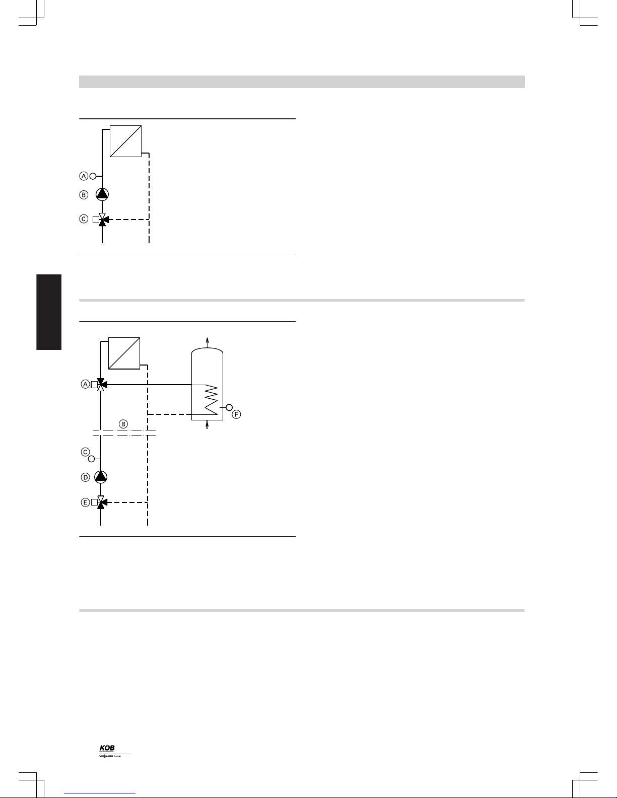
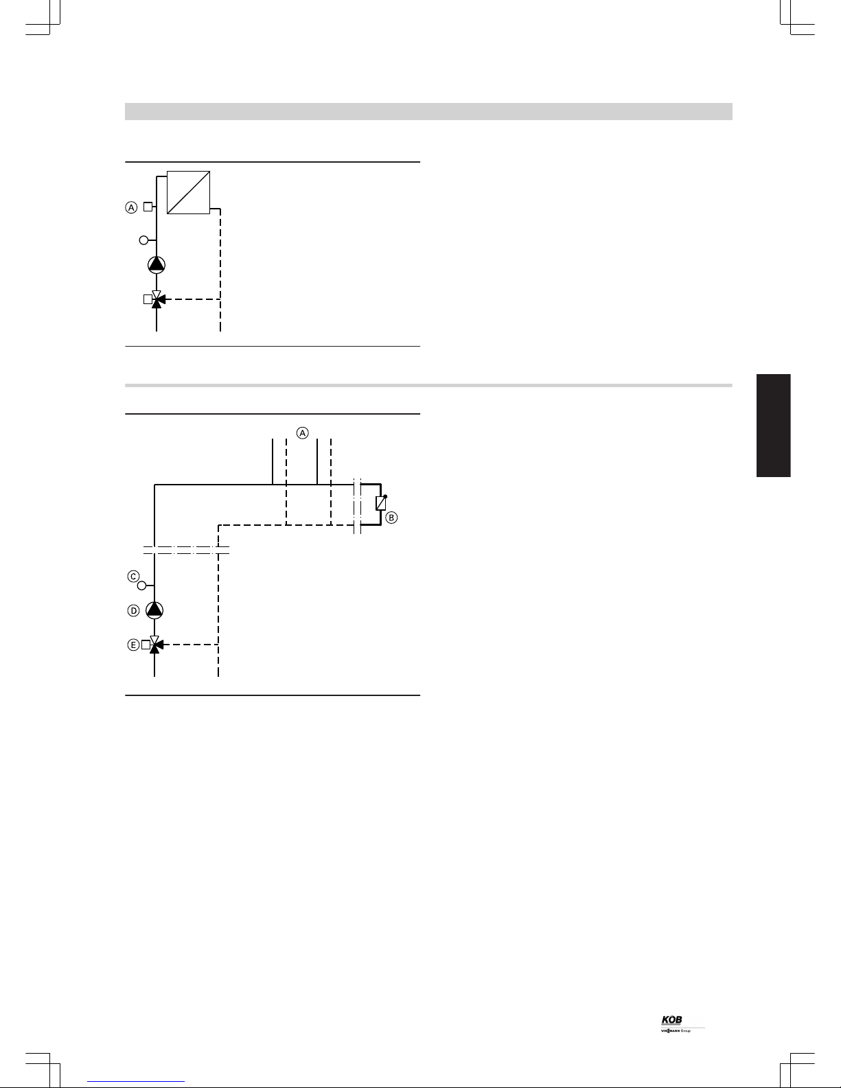
Controller, central heating
A
Contact sensor QAD 21
B
Pump
C
Mixing valve
Part no. 7379 402
Weather-compensated heating control unit with digital time switch for
setback mode according to individual day and seven-day program,
with pump control unit, frost protection function, eco mode and limited
flow temperature.
Standard delivery:
■ Button, central heating
■ Controller output for pump and mixing valve
■ Contact sensor QAD 21
Controller, adjacent building
A
Diverter valve
B
Adjacent building
C
Contact sensor QAD 21
D
Pump
E
Mixing valve
F
Sensor QAZ
Part no. 7387 865
The cable to the adjacent building is controlled with weather compensation via the heating circuit control unit. The DHW cylinder is heated
with the selected maximum flow temperature. For this, the heating
water is diverted to the DHW cylinder via a valve. Via the time switch,
the DHW cylinder is reheated in the downtimes (setback periods).
Standard delivery:
■ Button, adjacent building
■ Controller output for pump, mixing valve and diverter valve
■ Contact sensor QAD 21
■ Sensor QAZ 21.5220 with sensor well ½" x 200 mm
Room controller QAA 35
Part no. 7379 405
Addition to the controller for central heating and controller for adjacent
building. The room controller can be connected as a remote control
and as a room temperature sensor (room temperature compensation).
Standard delivery:
■ Room controller QAA 35
Control unit
(cont.)
16
PYROT
3
5822 516 GB
Page 17
Safety thermostat RAK-TW.1000B
A
Safety thermostat RAK-TW.1000B
Part no. 7387 940
For safe limitation of the flow temperature of a heating circuit.
Standard delivery:
■ Safety thermostat RAK-TW.1000B
Controller, long-distance line
A
Sub-distributor
B
Bypass
C
Contact sensor QAD 21
D
Pump
E
Control valve
Part no. 7379 401
Via a long-distance line, a building is supplied with separate heat distribution. The long-distance line is controlled upstream according to
the demand of the heating circuits. The heating circuits of the separate
heat distribution must be controlled via the Ecotronic.
Standard delivery:
■ Button, long-distance line
■ Controller output for pump and control valve
■ Contact sensor QAD 21
Note
The long-distance line controller module can only be used while Köb
controller modules in the sub-distributor are also being used.
Control unit
(cont.)
PYROT
17
5822 516 GB
3
Page 18
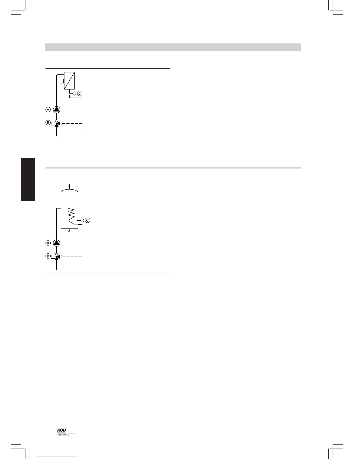
Controller, space heater
A
Pump
B
Mixing valve
C
Contact sensor QAD 21
Part no. 7387 825
The space heaters are supplied with maximum flow temperature by
the boiler cylinder system.
The switching of the fan is carried out by on-site switches or controllers.
The flow rate of the heating water is controlled via the return temperature and matched to the output of the space heater (flow control). This
results in optimum cylinder stratification with sustained high temperature at the cylinder flow. The heating periods (individual day and
seven-day program) can be adjusted via the integrated time switch.
Standard delivery:
■ Button, space heater group
■ Controller output for pump and mixing valve
■ Contact sensor QAD 21
■ Restrictor, bypass
Controller, DHW cylinder B1
A
Pump
B
Two-way valve
C
Sensor QAZ 21.5220
Part no. 7387 853
When its temperature drops, the DHW is reheated via the integral heat
exchanger directly by the boiler or by the buffer cylinder. This is
dependent on a corresponding difference in temperature (either differential temperature or fixed temperature control unit).
The heating periods (individual day and seven-day program) can be
individually adjusted via the integral time switch.
Standard delivery:
■ Button, DHW cylinder
■ Controller output for pump and two-way valve
■ Sensor QAZ 21.5220 with sensor well ½" x 200 mm
Control unit
(cont.)
18
PYROT
3
5822 516 GB
Page 19
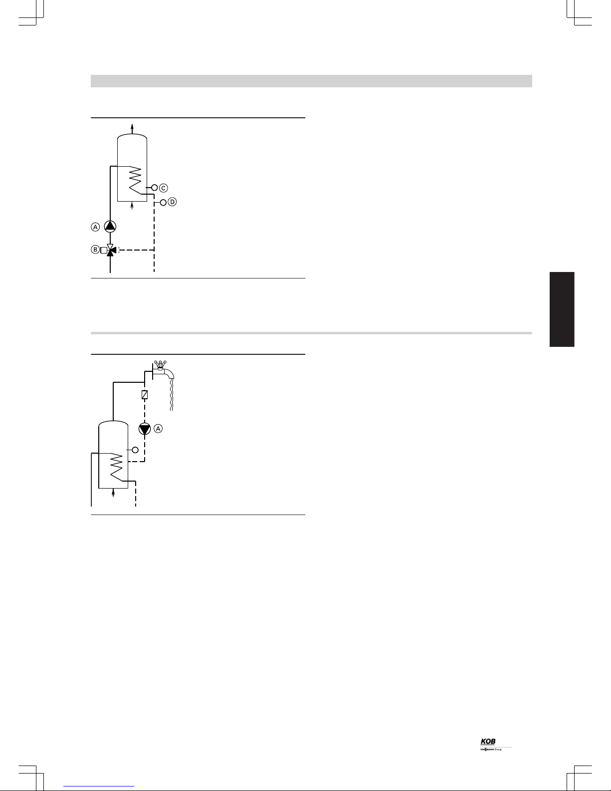
Controller, DHW cylinder B2
T
A
Pump
B
Control valve
C
Sensor QAZ 21.5220
D
Contact sensor QAD 21
Part no. 7379 400
When its temperature drops, the DHW is reheated via the integral heat
exchanger directly by the boiler or by the buffer cylinder. This is
dependent on a corresponding difference in temperature (either differential temperature or fixed temperature control unit).
The flow rate of the heating water is controlled via the return temperature (flow control). This results in optimum buffer cylinder stratification
with sustained high temperature at the cylinder flow. The heating periods (individual day and seven-day program) can be adjusted via the
integrated time switch.
Standard delivery:
■ Button, DHW cylinder
■ Controller output for pump and control valve
■ Contact sensor QAD 21
■ Sensor QAZ 21.5220 with sensor well ½" x 200 mm
Controller, DHW circulation
T
A
Pump
Part no. 7387 849
The circulation periods (individual day and seven-day program) can
be adjusted via the integral time switch.
The start-up duration of the DHW circulation pump can be adjusted via
timed cycling.
Standard delivery:
■ Button, DHW circulation
■ Controller output for pump
Control unit
(cont.)
PYROT
19
5822 516 GB
3
Page 20
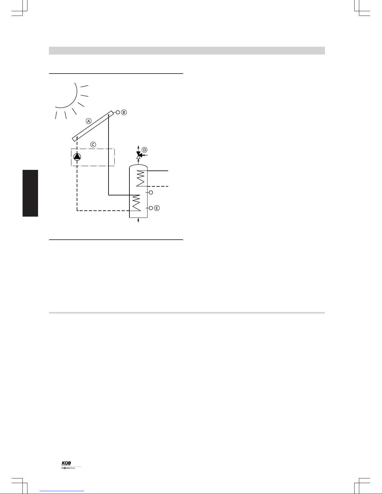
Controller, solar DHW cylinder
T
T
T
KW
WW
KW
HV
HR
RL
VL
HR Heating return
HV Heating flow
KW Cold water
RL Return (solar)
VL Flow (solar)
WW DHW
A
Solar collector
B
Collector temperature sensor
C
Solar station with solar circuit pump
D
Thermostatic water mixer
E
Cylinder temperature sensor QAZ 21.5220
Part no. 7387 818
Use for single solar thermal system as a single circuit control unit for
heating the DHW in the solar DHW cylinder.
If the temperature of the DHW (in the lower section of the DHW cylinder) falls below the collector temperature, the DHW is heated by the
solar collector (adjustable differential temperature: 2 - 20 °C).
Note
The controller for the solar DHW cylinder can only be used in conjunction with a controller for a DHW cylinder (B1 or B2).
Run-on time of the solar circuit pump adjustable from 0 to 120 s (subject to line length).
Maximum DHW temperature adjustable from 20 to 90 °C.
Safety: the solar circuit pump switches off at 140 °C collector temperature; restarts at 120 °C.
Standard delivery:
■ Button, solar
■ Collector temperature sensor PT-1000
■ Cylinder temperature sensor QAZ 21.5220
■ Controller output for the solar circuit pump
Controller, solar/DHW and central heating
Part no. 7387 786
Use for a larger solar thermal system for heating the DHW in the solar
DHW cylinder and for heat supply to the heating cylinder as a threecircuit control unit.
The first circuit is used to heat the DHW, the second heats the heating
cylinder back/bottom and the third heats the heating cylinder front/top.
The heating cylinder is heated with an external plate heat exchanger.
Changing over from the DHW cylinder to the heating cylinder starts the
secondary pump. This then operates with the solar circuit pump. For
optimum functioning, the flow rate in the secondary circuit must be
matched to the primary circuit (e.g. with flow meter in the primary and
secondary circuits).
Differential temperature, collector/DHW 2-20 °C.
The following differential temperatures are freely adjustable:
differential temperature, collector/cylinder back/bottom 2-20 °C.
Note
Controller, solar/DHW and central heating can only be used in conjunction with a controller for a DHW cylinder (B1 or B2).
Run-on time of the solar circuit pump adjustable from 0-120 s (subject
to line length).
Shutdown safety:
■ At 140 °C collector temperature
■ At 95 °C cylinder temperature
Optimised DHW priority (either absolute or no DHW priority).
Cylinder heating with stratification in accordance with the cylinder temperatures via a charging valve for the cylinder front/back.
Standard delivery:
■ Button, solar
■ Collector temperature sensor PT-1000
■ Cylinder temperature sensor QAZ 21.5220
■ Controller output for the solar circuit pump
■ Controller output, charging valve, DHW cylinder
■ Controller output for secondary pump
■ Controller output, charging valve, cylinder back/cylinder front
Control unit
(cont.)
20
PYROT
3
5822 516 GB
Page 21
KW
WW
--M20--
--Y20--
---
--Y6X.1--
--Y6X.2--
--Y6X.1--
--M6X.1--
--B6X.2--
--B6X.1--
--M6X.1--
---
--B6X.1--
--B28.1--
--B28.2--
--B28.3--
CAN
B
--B6X.2--
--M6X.2-2
4
2
2
3
4
3
2
2
4
3
2
4
2 2
4
3
E
Return
Flow
A
D
B
C
G
F
H
KW Cold water
WW DHW
A
Solar collector
B
Solar station with solar circuit pump
C
Thermostatic water mixer
D
Plate heat exchanger
F
Secondary pump
G
Charging valve, buffer cylinder front/back
H
Boiler
Control unit
(cont.)
PYROT
21
5822 516 GB
3
Page 22

3.3 Accessories for ECOTRONIC output management
Cylinder management 3 sensors
Part no. 7387 828
Modulating output operation of the PYROT rotation combustion system is optimised with the use of a buffer cylinder. Short term heat
demand peaks are also covered. The temperature sensors record the
heating of the buffer cylinder. The combustion output is matched to the
charging level of the buffer cylinder.
Standard delivery:
■ 2 additional sensors KTY with sensor well 1/2" x 280 mm
Cylinder management 5 sensors
Part no. 7387 852
Modulating output operation of the PYROT rotation combustion system is optimised with the use of a buffer cylinder. Short term heat
demand peaks are also covered. The temperature sensors record the
heating of the buffer cylinder. The specification of the charging level of
the buffer cylinder is weather-compensated and carried out via the
outside temperature sensor. The combustion output is matched to the
charging level of the cylinder.
Standard delivery:
■ 4 additional sensors KTY with sensor well 1/2" x 280 mm
Note
Part no. 7379 403 controller module and
Part no. 7387 587 data cable required.
External requirement ON/OFF
Part no. 7387 855
Input for automatic switching on/off of the system via external floating
N/O contact.
Operating message potential-free
Part no. 7387 934
If the PYROT boiler is operating on higher control technology, the
operating condition "Load operation" (potential-free output) is issued.
Standard delivery:
■ Potential-free output (operating message)
Output signals 0-10 V
Part no. 7387 800
Issuing of boiler output as voltage signal and a connection to receive
a maximum limit of the boiler output included in standard delivery.
Functions:
■ Issue of the output signals
■ Receipt and processing of an external output restriction
– 0 - 0.5 V... OFF
– 0.6 – 3 V... Standby
– 3.1 – 10 V... 30 % to 100 % output range
Note
Note: The installation of "Output signals 0 – 10 V" downstream of
QM wood heating plants is possible irrespective of additional control
modules used.
Control unit
(cont.)
22
PYROT
3
5822 516 GB
Page 23

3.4 Accessories for ECOTRONIC remote transfer
Fault message device, analogue with battery
Part no. 7387 994
Four different text messages are possible, as the fault message
modem has four independent digital inputs.
Standard delivery:
■ Analogue modem in control panel
■ Battery station (also works in event of a power failure)
To be carried out on customer side:
■ Electrical connection of the phone line to the modem
■ Configuration in accordance with the documentation
Export of operating data
Part no. 7388 038
Issue of relevant operating data and fault messages of the boiler system as ASCII dataset via serial interface to higher control technology
on the customer side. If permitted by the control technology, the higher
control technology can change all adjustable parameters.
Standard delivery:
■ Interface at the control panel
■ Software module
■ MOD-BUS protocol
Note
Additional fault message device, analogue with battery station, part
no. 7387 994, possible
Additional visualisation, wired or wireless, part no. 7388 003, not
possible
Visualisation Pyrot - internal
Part no. 7387 839
With a data cable (max. 30 m), all data can be fed via the serial interface RS 232 from the programming module to the PC. The current
operating data for the boiler system is displayed visually on a function
screen. All options for inputting values and functions and reading out
the operating conditions (exception: "Start boiler)" are shown. All operating data is archived cyclically and can be evaluated graphically in an
extremely simple way.
Note
The PC and data cable are not included in the price.
Standard delivery:
■ CD with visualisation software and installation instructions
Note
Requirements for on-site PC:
Operating system: Windows 98 / 2000 / XP
At least 50 MB free hard disk memory
At least 128 MB RAM
1 free serial interface per boiler
Visualisation, additional functions
Part no. 7387 821
Extension of visualisation [ECO VII] with the functions of additionally
enabled buttons (from F4). Additional functions include each heating
controller (heat source, heat consumer, solar) and automatic charging.
Every button function is shown on a separate function screen with all
options for entering values, reading out the operating conditions and
archiving. Price per piece for additionally enabled button on programming module.
Standard delivery:
■ Extension of the visualisation software CD
Data cable to visualisation - internal
Part no. 7379 404
Data cable comprising:
■ D-SUB connector for connection between programming module and
data cable, soldered
■ 30 m data cable 3-pole (cut to length as required on site)
■ D-SUB connector with threaded fittings, 9-pole for connection to the
PC
Control unit
(cont.)
PYROT
23
5822 516 GB
3
Page 24

Visualisation, externally via modem (connected with cable)
Part no. 7387 792
Package for the transmission of relevant data to an EDP workstation
(internal and/or external) for the visualisation, remote maintenance
and operating data archiving of the PYROT boiler system. Hardware
and software are integrated into the Ecotronic control unit. All adjustable parameters can be changed from the EDP workstation.
Standard delivery:
■ Industrial PC with interfaces for screen, keyboard and PC mouse for
EDP workstation close to boiler room
■ Analogue modem in control panel
■ Windows operating system, remote maintenance software pcAnywhere and visualisation/archiving software installed and tested on
the industrial PC.
Images on the screen:
■ Cross-section image of boiler, 3D with display fields
■ Installation scheme for heat source with display fields
■ Table of parameters (with change option)
To be carried out on customer side:
■ EDP workstation for remote maintenance together with modem,
installation of pcAnywhere and modem is to be set up independently
by the customer
Note
Additional fault message device, analogue with battery station, part no.
7387 994, possible
Additional export of operating data, part no. 7388 038, not possible
Control unit
(cont.)
24
PYROT
3
5822 516 GB
Page 25

3.5 Mastercontrol for two-boiler systems
The Mastercontrol optimises the entire heat generation of two biomass
boilers (PYROT dual system) incl. control of an oil, gas or electric boiler
as a redundancy and/or as a peak load boiler.
Information on the Mastercontrol
Function:
■ Heat management:
Optimum division of the required output between the two biomass
boilers with the main load on the lead boiler and the remaining load
on the lag boiler via a default output value. The default output is
calculated in accordance with QM wood heating stations in line with
the required set temperature in the common low loss header. Automatic switchover of the two boilers between the lead boiler and the
lag boiler is possible. This ensures an even boiler load over a long
operating time (e.g. weekly changeover).
■ Charging:
If fuel for the two biomass boilers is taken from a common fuel store,
charging is controlled up to fuel distribution by the Mastercontrol.
■ Operating data archiving:
Relevant operating data of the past 31 days is stored in a ring buffer
and can easily be displayed in graph form on the Mastercontrol
touch-screen.
Operation:
Operation is carried out via a 10“ touch-screen integrated in the control
panel.
Standard delivery
■ Control panel, loose,
surface powder-coated in RAL 7035 (grey) texture. Version as per
ÖVE/VDE directives fully wired to terminal strips, feed 3 x 400 V 50
Hz; control voltage 230 V or 24 V
■ Freely programmable control unit, CE-tested, program and real time
clock are battery backed
■ Contactor/motor overload relay combinations for all common charging drives (3 x 400 V) according to separate price items
■ Ethernet interface (network connection) on touch panel
■ Potential-free output (fault message)
■ 10“ touch-screen
■ 4-pole main isolator
■ Documentation incl. fixed wiring diagram
■ Terminal connection diagram with cable designation in plan pocket
■ Heater management 5 sensors (QM)
■ 5 sensors PT-1000 with sensor well 1/2" x 280 mm
■ 1 weather sensor PT-1000
■ Default output value for both biomass boilers for processing in the
subordinate boiler control units via CAN BUS
Note
Remote maintenance with PC or network, water-side and electrical
installation on customer side.
Visualisation with touch-screen
■ Operating data archive
■ Display and archiving of the relevant
■ Operating data of both wood boiler systems and the Mastercontrol
■ Easy operation of the wood boiler systems at the touch-screen of the
Mastercontrol
■ Installation scheme for heat source with display fields
■ Table of parameters (with parameter setting options)
■ Fault history
Control unit
(cont.)
PYROT
25
5822 516 GB
3
Page 26
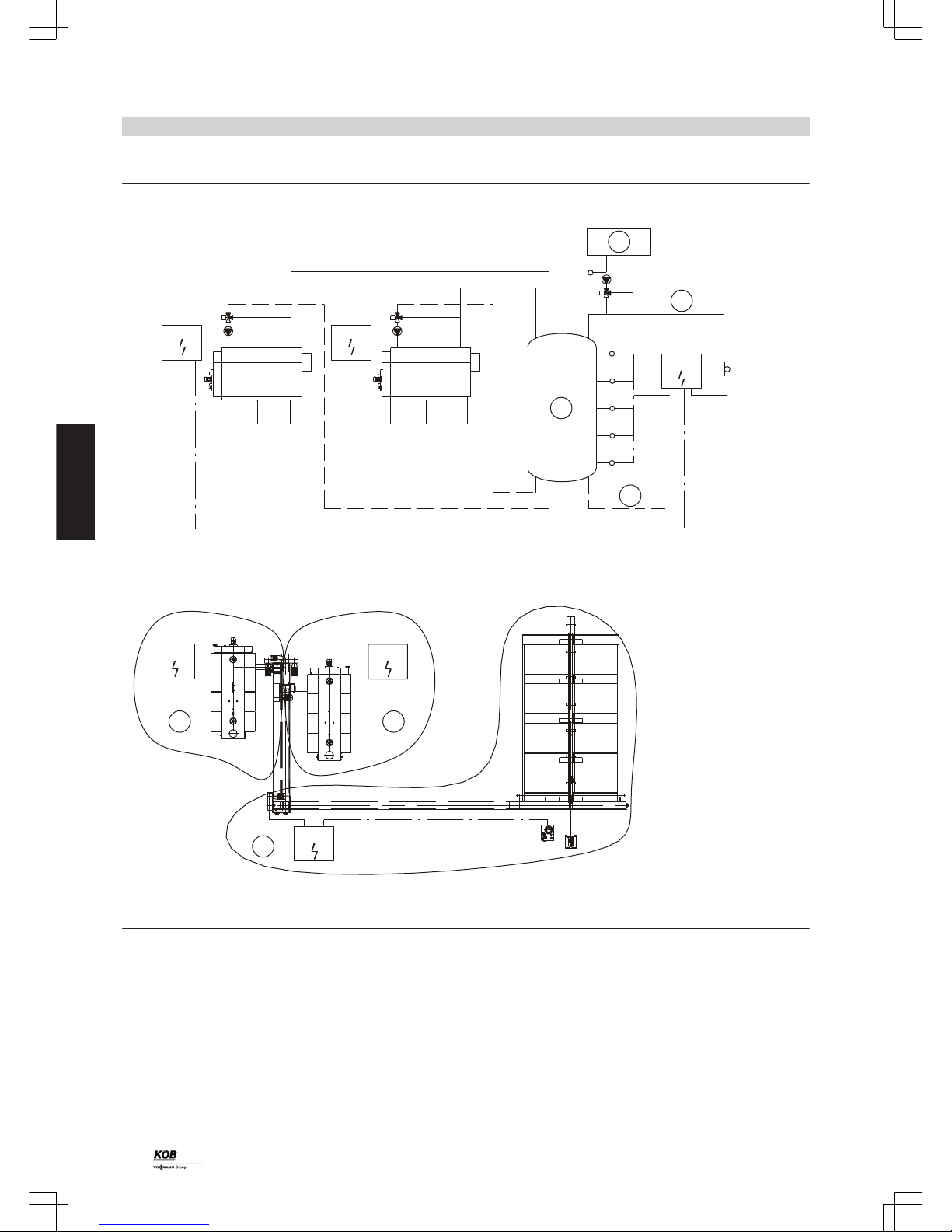
Schematic diagram
M
T
T
T
T
T
M
M
T
1
PYROT 1 PYROT 2
2
ECOTRONIC ECOTRONIC
MASTERCONTROL
A
B
C
D
B28.1
B28.5
B28.4
B28.3
B28.2
ECOTRONIC
1
ECOTRONIC
2
E F
1
2
G
MASTERCONTROL
Schematic diagram of a two-boiler system with Mastercontrol
A
Additional heat source
B
Flow consumers
C
Buffer cylinder as low loss header
D
Return consumers
E
Exclusively charging boiler 1 in control unit boiler 1
F
Exclusively charging boiler 2 in control unit boiler 2
G
Common charging, control unit modules
Control unit
(cont.)
26
PYROT
3
5822 516 GB
Page 27

3.6 Accessories for Mastercontrol
Heat meter signal
Part no. 7387 975
Note
Only for Mastercontrol.
With this analogue input (0-10 V signal), the external heat meter can
be read into the Mastercontrol. The current values can be displayed
on the screen. The heat meter data is archived in the visualisation.
Requirement, additional heat source KP0
Part no. 7387 923
Function:
The additional heat source supplies, individually or jointly with the
boiler, heat to the buffer cylinder. This is designed as a low loss header.
Taking into consideration the inertia of the boiler, the boilers are controlled so that the additional heat source covers the peak load and the
wood boiler covers the base load. In the operating phase of the additional heat source, the boiler pump is operating and the motorised
shut-off device is open.
Standard delivery:
■ Sub-menu on touch-screen
■ Contactor and motor overload relay, boiler circuit pump, additional
heat source
■ Control of motor, shut-off device
■ Floating contact for the control of the burner
■ Sensor PT-1000 incl. sensor well ½” x 280 mm loose (installation in
low loss header-system sensor)
Note
The electrical output data of the on-site boiler pump (kW, ampere, volt)
must be given.
Requirement, additional heat source KP1
Part no. 7387 908
Function:
The additional heat source supplies, individually or jointly with the
boiler, heat to the buffer cylinder. This is designed as a low loss header.
Taking into consideration the inertia of the boiler, control is carried out
so that the additional heat source covers the peak load and the boiler
covers the base load. In the operating phase of the additional heat
source, the boiler pump is operating and the control unit of the boiler
mixer is enabled.
Standard delivery:
■ Sub-menu on touch-screen
■ Contactor and motor overload relay, boiler circuit pump, additional
heat source
■ Control of motor, shut-off device
■ Floating contact for the control of the burner
■ Sensor PT-1000 incl. sensor well ½” x 280 mm loose (installation,
return of additional heat source)
■ Sensor PT-1000 incl. sensor well ½” x 280 mm loose (installation in
low loss header-system sensor)
Note
The electrical output data of the on-site boiler pump (kW, ampere, volt)
must be given.
Pt1000
Control unit
(cont.)
PYROT
27
5822 516 GB
3
Page 28

Fault message device, analogue with battery
Part no. 7387 840
Transmits the boiler system fault messages as a phone message. The
fault message must be acknowledged. Four different text messages
are possible, as the fault modem has four independent digital inputs.
Standard delivery:
■ Analogue modem in control panel
■ Battery station (also works in event of a power failure)
To be carried out on customer side:
■ Electrical connection of the phone line to the modem
■ Configuration in accordance with the documentation
Export of operating data
Part no. 7387 890
Issue of relevant operating data and fault messages of the boiler system via MOD-BUS as ASCII dataset via a serial interface to higher
control technology on the customer side. If the option is available, the
higher control technology can change all adjustable parameters.
Standard delivery:
■ Interface at the control panel
■ Software module
■ MOD-BUS protocol
Note
■ Additional fault message device, analogue with battery station possible (part no. 7387 840)
■ Additional visualisation, wired (part no. 7387 997) or wireless (part
no. 7387 874) possible
Control unit
(cont.)
28
PYROT
3
5822 516 GB
Page 29
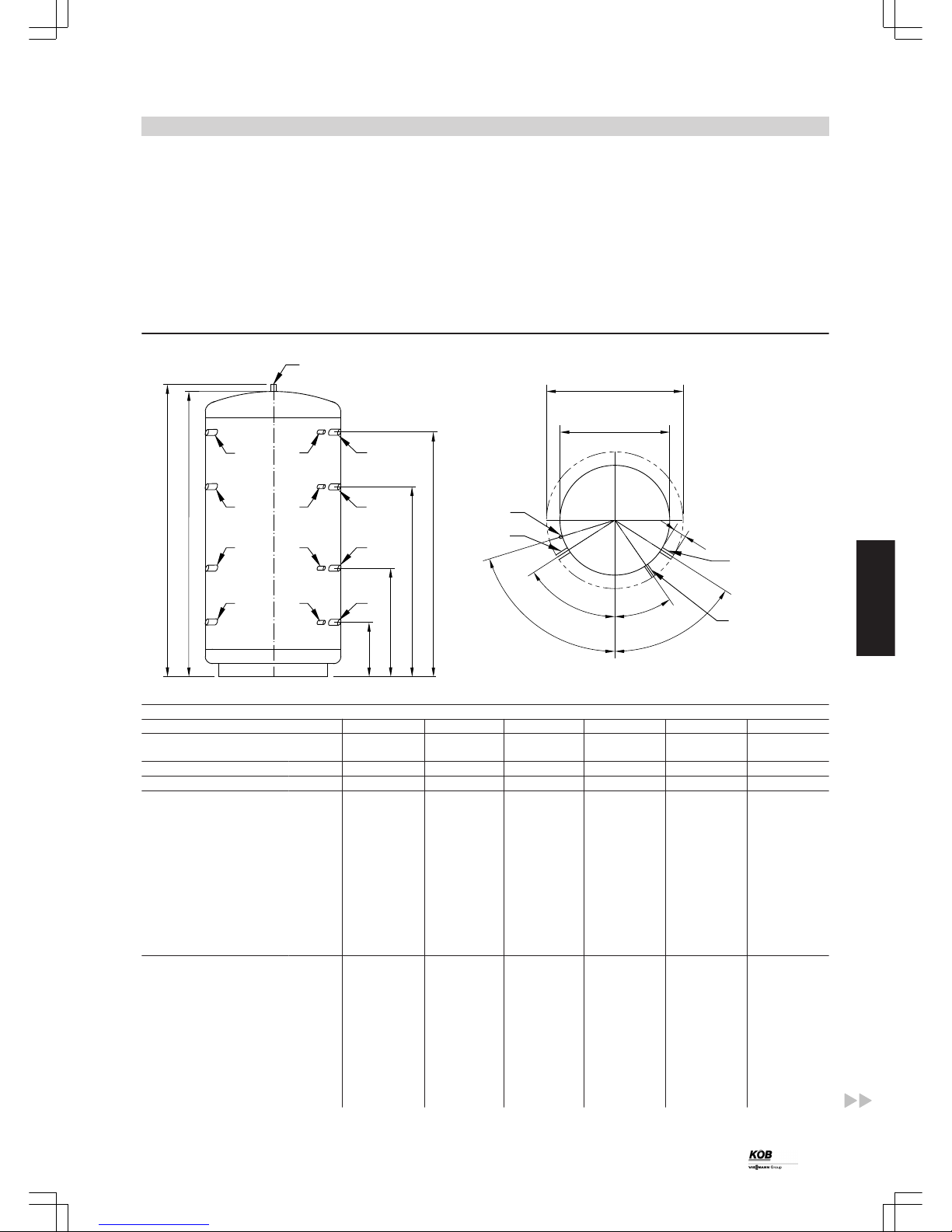
4.1 Specification, buffer cylinder
Buffer cylinder HPM
Buffer cylinder for integration in a wood combustion system with a
maximum boiler output of up to 150 kW.
Version:
■ Steel S 235 JRG2, untreated inside, anti-rust coating outside
■ Operating pressure: max. 3.0 bar; test pressure: 4.5 bar
■ Connections: 8 female connections R 1½, 4 female connections
R ½, 1 sensor pipe 14 x 1.5 mm, 1 female connection top R 1¼
Flexible foam insulation to HPM
The insulation is made from 100 mm thick flexible PUR foam elements
with polystyrene casing.
Fire safety category B3.
Note
Delivery is ex-stock.
Alternative cylinder sizes and insulation types on request.
e
a
b
c
d
03
f
01
01
01
01
01
01
01
01
02
02
02
02
01
02
1
4
o
k
l
m
n
g
h
Part no. buffer cylinder HPM 7424130 7424131 7424132 7424133 7424134 7424135
Part no. flexible foam insulation to
buffer cylinder HPM
7424136 7424137 7424138 7424139 7424140 7424141
Contents l 1000 1250 1500 2000 2500 3000
Weight kg 170 176 185 211 260 300
Dimensions
Height when tilted mm 2080 2070 2200 2410 2375 2780
a mm 310 310 380 320 535 380
b mm 745 745 825 900 975 1020
c mm 1250 1250 1350 1490 1415 1680
d mm 1710 1710 1760 2020 1855 2330
e mm 1993 1948 2098 2308 2217 2655
f Total height mm 2043 1998 2148 2358 2267 2705
g Diameter without
insulation
mm 790 950 1000 1100 1250 1250
h Diameter with insula-
tion
mm 990 1150 1200 1300 1450 1450
Connections
k 50° 50° 50° 50° 50° 50°
l 50° 50° 50° 50° 50° 50°
m 28.2° 31.9° 32.8° 34.3° 36.2° 36.3°
n 70° 70° 70° 70° 70° 70°
o Length of female con-
nections
mm 100 100 100 100 100 100
01 Female connections,
flow/return
R 1½ 1½ 1½ 1½ 1½ 1½
02 Female connections,
sensor
R ½ ½ ½ ½ ½ ½
Heating water buffer cylinder
PYROT
29
5822 516 GB
4
Page 30

Part no. buffer cylinder HPM 7424130 7424131 7424132 7424133 7424134 7424135
Part no. flexible foam insulation to
buffer cylinder HPM
7424136 7424137 7424138 7424139 7424140 7424141
03 Female connection,
top
R 1¼ 1¼ 1¼ 1¼ 1¼ 1¼
04 Sensor pipe Ø14xL1400 Ø14xL1400 Ø14xL1400 Ø14xL1700 Ø14xL1250 Ø14xL1700
Buffer cylinder WDW 2000 l
Part no. 7424 538
Buffer cylinder for integration in a wood combustion system with a
maximum boiler output of up to 540 kW.
Version:
■ Steel S 235 JRG2, untreated inside, anti-rust coating outside
■ Operating pressure: max. 3.0 bar; test pressure: 4.5 bar
■ Connections: 4 flanges DN 80 / PN 6, 3 female connections R ½, 1
female connection R 1½, 1 female connection R ¾
Rigid foam insulation to WDW 2000 l
Part no. 7424 540
The insulation is made from approx. 90 mm thick rigid foam shells
(single part or multi part polystyrene) incl. cover.
Fire safety category B2.
Note
Delivery is ex-stock.
Alternative cylinder sizes and insulation types on request.
01
f
e
d
c
b
a
h
k
g
02
03
04
02
02
01 01
01
m
l
o
n
Part no. buffer cylinder WDW 2000 l 7424 538
Part no. rigid foam to buffer cylinder WDW 2000 l 7424 540
Contents l 2000
Weight kg 220
Dimensions
Height when tilted mm 2170
a mm 280
b mm 750
c mm 1165
d mm 1265
e mm 1480
f mm 1580
g mm 1680
h mm 2010
k Total height mm 2025
l Diameter without insulation mm 1200
m Diameter with insulation mm 1400
Connections
o Length of female connections mm 100
01 Flow/return flange DN80/PN6
02 Female sensor connections R ½
03 Female sensor connection R ¾
04 Reserve R 1 ½
Heating water buffer cylinder
(cont.)
30
PYROT
4
5822 516 GB
Page 31

Buffer cylinder WDW 2900 l
Part no. 7439 106
Buffer cylinder for integration in a wood combustion system with a
maximum boiler output of up to 540 kW.
Version:
■ Steel S 235 JRG2, untreated inside, anti-rust coating outside
■ Operating pressure: max. 3.0 bar; test pressure: 4.5 bar
■ Connections: 4 flanges DN 80 / PN 6, 5 female connections R ½, 1
female connection R 1½, 1 female connection R ¾, 1 ventilation
facility
Rigid foam insulation to WDW 2900 l
Part no. 7439 107
The insulation is made from approx. 90 mm thick rigid foam shells
(single part or multi part polystyrene) incl. cover. Fire safety category
B2.
Note
Delivery is ex-stock.
Alternative cylinder sizes and insulation types on request.
s
r
q
t
a
b
c
d
e
f
g
h
k
l
m
n
m
o
p
8
1
2
1
4
1
1
1
8
8
8
12
20
Part no. buffer cylinder WDW 2900 l 7439 106
Part no. rigid foam to buffer cylinder WDW 2900 l 7439 107
Contents l 2900
Weight kg 295
Dimensions
Height when tilted mm 2890
a mm 265
b mm 745
c mm 1155
d mm 1560
e mm 1785
f mm 1920
g mm 2130
h mm 2230
k mm 2465
l mm 50
m mm 280
n mm 2200
o mm 20
p mm 2830
q Length of female connections mm 150
r mm 1300
s mm 1200
t ° 90
Connections
1 Temperature sensor R ½
2 Female sensor connections R ¾
4 E heater R 1 ½
8 Flow/return flange DN80/PN6
12 Ventilation R 1
20 Insulation mm 90
Heating water buffer cylinder
(cont.)
PYROT
31
5822 516 GB
4
Page 32

5.1 Boiler safety equipment
Thermally activated safety valve 100 °C
Part no. 7387 405
Standard version for response temperature approx. 100 °C, connection R . ¾
Standard delivery:
■ Thermally activated safety valve incl. sensor well
Note
We recommend the thermally activated safety valve even if there is
no need to use it in accordance with the local safety regulations.
Thermally activated extinguishing valve ½”, 50-90 °C
Part no. 7387 521
Thermally opening extinguishing valve with adjustable opening temperature for on-site connection to a pressurised water line or an extinguishing water container.
Standard delivery:
■ Extinguishing valve Danfoss AVTA, adjustable 50-90 °C with dirt trap
Supply screw conveyor two-level
Part no. 7387 831
Version with two-level supply screw conveyor. This enables operation
matched to the fuel used. It is optimised for shavings/woodchips (high
level) on the one side and for pellets (low level) on the other.
Standard delivery:
■ Geared motor, supply screw conveyor, pole-changing 750/
300 rpm
■ Starttec for geared motor, pole-changing
■ Software module in the control unit
Insulation, flue gas recirculation line
High temperature-resistant insulation 35 mm thick made from mineral
wool with aluminium lamination and side adhesive strips for straight
elements of the flue gas recirculation line. Aluminium foil adhesive
strips for the faces are also supplied.
Designation Part no.
Insulation, flue gas recirculation line, per m, DN
80
7387 421
Insulation, flue gas recirculation line, per m, DN
125
7388 023
Installation accessories
32
PYROT
5
5822 516 GB
Page 33

5.2 Accessories, heat distribution
Motor three-way valve for Pyrot 100 kW
Designation Rated output Part no.
Motor three-way valve, VXG 48.40/SQS 35.0 (ZV-3-40) 100 kW 7388 204
Precise control characteristics and an airtight seal without leaks.
Type DN
[mm]
Kvs
[m3/h]
Servomotor
230 V
Incl. complete fitting Rated output
ZV-3-40 40 20 SQS 35.00 R 1½ – G 2¼ 100 kW
Note
No individual issue: delivery only as part of an overall system.
Motor three-way valve for Pyrot 150-540 kW
Designation Rated output Part no.
Motor three-way valve, VBF 21.50/SQL 33 (ZH-3-50) 150 kW and 220 kW 7388 100
Motor three-way valve, VBF 21.65/SQL 33 (ZH-3-65) 300 kW 7388 160
Motor three-way valve, VBF 21.80/SQL 33 (ZH-3-80) 400 kW and 540 kW 7388 260
Rated output Type DN [mm]
Kvs [m3/h]
Servomotor 230
V
Incl. complete fitting
150 kW and 220 kW ZH-3-50 50 40 SQK 33 Mating flanges, gaskets
300 kW ZH-3-65 65 63 SQL 33 Mating flanges, gaskets
400 kW and 540 kW ZH-3-80 80 100 SQL 33 Mating flanges, gaskets
Note
No individual issue: delivery only as part of an overall system.
Pumps
Rated output Designation Part no. DNmmVoltageVOutputWOutput
m3/h /
mWC
Incl. complete
fitting
Variable
speed
100 kW and 150 kW Wilo TOP-S 30/7 DM
(ZPS-328-4)
7388 134 30 400 65-200 7.5/7.0 R 1¼ – G 2 —
220 kW Wilo TOP-S 40/7 DM
(ZPS-406-4)
7388 108 40 400 130-370 16.5/7.0 Mating flanges,
gaskets
—
300 kW and 400 kW Wilo TOP-S 50/7 DM
(ZPS-506-4)
7338 271 50 400 245-625 28.0/7.0 Mating flanges,
gaskets
—
540 kW Wilo TOP-S 65/10 DM
(ZPS-656-4)
7388 221 65 400 400-960 42.0/9.0 Mating flanges,
gaskets
—
Note
We reserve the right to select the pump manufacturers and types.
Delivery only as part of an overall system or as a spare part.
Installation accessories
(cont.)
PYROT
33
5822 516 GB
5
Page 34

5.3 Accessories, flue system
Flue gas dust extractor
The flue gas dust extractor minimises dust emissions and is designed
as a multi cyclone with axial function. The dust extractor is fully insulated and has three covers for cleaning.
The raw gas space is cleaned via the side cleaning cover. The clean
gas space is cleaned via the upper or back cleaning cover (unused fan
connection).
The ash box has a carriage and is connected to the dust extractor with
quick-action fasteners. It can easily be pulled out for emptying. The fan
can be installed either on the side or the top.
Note
The flue gas dust extractor is required for fuels with an increased percentage of fines (> 4 %).
Rated output kW 100 150 220 300 400 540
Part number 7423 662 7423 663 7423 664 7423 665
Standard delivery:
■ 1 flue gas dust extractor
■ 1 ash container hopper volume 90 litres
Note
Additional ash containers must be ordered separately.
Ash container 90 l, reserve
Part no. 7388 045
Installation accessories
(cont.)
34
PYROT
5
5822 516 GB
Page 35

34,05 mm
7,69 mm
14,70 mm
23,34 mm10,05 mm2,19 mm
29,93 mm
47,92 mm
c
g
d
e
f
a
b
< 200
D
C
B
16,68 mm
14,12 mm
6,02 mm
10,57 mm
14,12 mm8,26 mm
8,86 mm
31,22 mm
4,07 mm
21,70 mm
820
r
p
r
820
n
m
l
< 200
h
q
k
25,44 mm
29,45 mm
28,23 mm
820
750
d
90 l
28,23 mm
28,23 mm
820
820
A
Positioning in 4x 90° possible (removal, ash container)
A
Flue gas fan (with variable rotation)
■ Either top or side
■ Unused connection as cleaning cover, clean gas space
B
Cleaning cover (raw gas space)
C
Dust extractor (axial cyclone)
D
Ash station
k Recirculation gas to boiler
q Flue gas to chimney
Dimensions
Rated output kW 100 and 150 220 and 300 400 540
Part no. 7423 662 7423 663 7423 664 7423 665
Dimensions
a mm 1521 1628 1671 1741
b mm 2285 2552 2702 2776
c mm 1518 1775 1875 1949
d mm 846 846 846 920
e mm 899 1156 1256 1256
f mm 540 550 600 600
g mm 430 424 447 447
h mm 545 530 977 977
l mm 1640 1440 1790 1790
m mm 414 414 480 480
n mm 280 370 370 370
o mm 614 614 620 620
r mm 780 780 1260 1260
Weight
Weight with flue gas fan kg 295 315 350 350
Weight without flue gas fan kg 258 270 310 288
Installation accessories
(cont.)
PYROT
35
5822 516 GB
5
Page 36

Metal mesh filter
The metal mesh filter removes dust and fine dust from the flue gas. It
is characterised by a particularly high degree of separation. This
ensures a fine dust content of less than 20 mg/Nm³ in the clean gas.
The flue gas dust extractor (cyclone separator) is not required in this
case.
The metal mesh filter comprises two block-shaped units joined
together. The compact design enables it to also be used in low level
boiler rooms. The filter cartridges are robust and resistant to a shower
of sparks.
Function:
The filter is operated with underpressure. With the cylindrical filter cartridges, the flow is from outside in. The filter cartridges are protected
against condensation by means of a heating system and are therefore
protected against corrosion. In the case of boiler demand, the filter
cartridges are preheated. If the set filter temperature is reached, boiler
start-up operation is enabled. If the temperature falls below the set filter
temperature, the filter heating system starts in heating mode. The filters are cleaned automatically in the countercurrent. This means that
the dust layer on the mesh is regularly discarded into the ash box.
Filter operation is controlled via the boiler control unit. Operation is
carried out via the control unit programming module.
Standard delivery:
■ Two-part, insulated filter casing with:
– Hinged raw gas doors, lockable by means of a quick-action fas-
tener and lock
– Maintenance cover for clean gas space
– Filter cartridges
– Ash box
■ Electric heater
■ Pneumatic cleaning
■ Flue gas fan for boiler and filter
■ Control panel fully wired.
On-site tasks:
Provision of a compressor or a connection to a compressed air line
system (pressure level 4–6 bar) and a power supply 3 x 400 V, 25 A.
19,28 mm
4,11 mm
> 200
d
c
b
a
A
B
C
D
E
g
h
f
e
k
l
m
n
F
K
H
> 150
t
sr
> 200
qp
o
D
L
P
M
N
O
19,28 mm
4,11 mm
> 200
d
c
b
a
A
B
C
D
E
g
h
f
e
k
l
m
n
F
H
G
> 150
t
sr
> 200
qp
o
D
K
O
L
M
F
A
Clean gas collector
B
Raw gas distributor (connection possible on both sides)
C
Recirculation gas connection
D
Clean gas to chimney
E
Raw gas from boiler (connection possible on both sides)
F
Flue gas fan (with variable rotation)
G
Control panel Ecotronic
H
Power supply 3 x 400 V, 25 A
K
Pressure bars for pneumatic cleaning
L
Control panel door
M
Compressed air connection
N
Raw gas door
Installation accessories
(cont.)
36
PYROT
5
5822 516 GB
Page 37

Dimensions
Rated output kW 220 300 400
Dimensions
a mm 1413 1413 1413
b mm 1833 1833 1833
c mm 460 460 460
d mm 300 300 350
e mm 2097 2097 2097
f mm 1720 1720 1720
g mm 2230 2230 2230
h mm 2820 2820 2827
k mm 1270 1270 1400
l mm 1670 1670 1717
m mm 1730 1730 1770
n mm 2255 2255 2400
o mm 840 840 840
p mm 900 900 900
q. mm 1192 1192 1040
r mm 1069 1069 1069
s mm 800 800 800
t mm 2200 2200 2200
Weight
Transport weight kg 470+470 470+490 490+490
Total weight kg 940 960 980
Note
Further dimensions on request.
Specification
Rated output kW 100 150 220 300 400 540
Part no. 7424 949 7423 697 7423 698 7423 699 7424 950
Suitable for continuous outputs of kW 24-80 41-135 60-200 80-270 100-360 144-480
Dust content in clean gas mg/Nm³ <20 <20 <20 <20 <20 <20
Volume of ash box l 2x45 2x45 4x45 4x45 4x45 6x45
Connection pressure drop Pa 1200 1200 1200 1200 1200 1200
Number of cartridges pce 3 4 6 7 8 12
Number of filter modules pce 1 1 2 2 2 3
Transport dimensions
Length mm 1103 1103 2200 2200 2200 3300
Width mm 1230 1230 1230 1230 1230 1230
Height mm 2100 2100 2100 2100 2100 2100
Sensor technology
Temperature sensor pce 2 2 2 2 2 3
Differential pressure cells pce 1 1 1 1 1 1
Electrical connections
Electrical connections total kW 13 13 13 13 13 13
Flue gas fan kW 2.2 2.2 2.2 3.0 4.0 4.0
Filter heating kW 9.0 9.0 9.0 9.0 9.0 9.0
Power consumption during cold
start
kW 4.5 4.5 4.5 4.5 4.5 4.5
Cleaning, pneumatic
The whole tubular heat exchanger is cleaned with periodic blasts of
compressed air during operation. The process of cleaning itself is carried out in consecutive blasting of the individual sections. The ash is
removed from the heat exchanger pipes by means of an extremely
short but strong pressure pulse. The device is installed on the back of
the boiler. The compressor should preferably be installed in a cool
place in the boiler room.
The number of cleaning processes within a unit of time (e.g. per hour)
is matched accordingly to the boiler load. An individual, complete
cleaning process comprises a sequence of pressure pulses across all
sections of the heat exchanger.
Standard delivery:
■ Nozzle part integrated in the flue gas collector; incl. connectors with
heat deflection discs
■ Compressed air distributor with container and valves, with heatresistant hoses connected to the nozzle part
■ Compressor (rotation compressor) for local applications
– Supply output 160 l/min
– Container 90 l
– Pressure max.10 bar
– Motor 1.5 kW
–
1450 rpm
– 3 x 400 V
– Incl. pressure regulator and pressure switch
– Sound level 68 dB(A)
■ Compressed air hose up to max. 4.0 m length
Installation accessories
(cont.)
PYROT
37
5822 516 GB
5
Page 38

■ Valves fully wired on terminal strip
■ Software module in the control unit
To be carried out on customer side:
■ Provision of a socket 400 V / 16 A
■ Connector for compressor 400 V / 16 A
Specification
Rated output kW 100 150 220 300 400 540
Part no.: 7423 666 7423 667 7423 668 7423 669 7423 670 7423 671
Number of zones/valves pce 3 4 4 4 5 6
Size of valves G 1 1 1 1 1 1
Max. air consumption under full load l/h 1300 1300 2500 2500 3300 4500
Price reduction net compressed air on site
Part no. 7388 288
This eliminates the need for the compressor listed in "Cleaning pneumatic". The compressor provided on the customer side must supply at
least the specific quantity and quality of the air and have an adjustable
pressure regulator and protection against hose break (e.g. runtime
limiter).
The compressor must also meet the following minimum requirements:
■ Compressor (rotation compressor) for local applications
– Supply output 160 l/min
– Container 90 l
– Pressure max.10 bar
– Motor 1.5 kW
–
1450 rpm
– 3 x 400 V
– Incl. pressure regulator and pressure switch
– Sound level 68 dB(A)
Installation accessories
(cont.)
38
PYROT
5
5822 516 GB
Page 39

5.4 Accessories, ash removal
External container
Complete screw conveyor ash removal from the ash chamber of the
combustion block into an external, mobile and zinc-plated ash container (standard 240 litres). The light barrier control unit keeps the ash
level via the screw conveyor constant. In this way, the ash can transfer
all its heat in the ash trough under the combustion system and only
cooled ash is fed into the container in normal operation.
Standard delivery:
■ Boiler ash trough with ash level control and ash removal screw conveyor made from heat-resistant steel
Driven via geared screw conveyor motor
■ Ascending ash screw conveyor as a pipe screw conveyor with direct
transfer from the ash removal screw conveyor
Driven via geared screw conveyor motor
■ Connection station with mobile ash container
■ Control of the screw conveyor drives
■ Infrared light barrier for level monitoring of ash in combustion chamber
A B
C D
Standard versions (A-D also possible reversed)
Connection station with mobile ash container can also be installed
rotated 90°. It is possible to select the direction in which the ash container is pulled out.
Installation accessories
(cont.)
PYROT
39
5822 516 GB
5
Page 40

15,91 mm
24,56 mm
10,42 mm
4,72 mm
1,98 mm
139
a
742
1118
1727
16,99 mm
14,61 mm
3,21 mm
6,12 mm
438
b
742
450
710
14,06 mm
Ash removal in external container 240 l
Dimensions
Rated output kW 100 150 220 300 400 540
Volume of ash container l 240 240 240 240 240 240
Part no.: 7387 918 7387 918 7387 918 7387 918 7387 918 7387 918
a mm 249 249 319 319 301 301
b mm 953 1023 1023 1193 1273 1408
16,99 mm
6,12 mm
438
b
1000
510
1000
5,89 mm
10,71 mm
13,44 mm
4,72 mm
1,98 mm
139
a
1000
1500
2460
9,83 mm
14,74 mm
24,70 mm
Ash removal in external container 800l
Dimensions
Rated output kW 100 150 220 300 400 540
Volume of ash container l 800 800 800 800 800 800
Part no.: 7387 950 7387 950 7387 950 7387 950 7387 950 7387 950
a mm 249 249 319 319 301 301
b mm 953 1023 1023 1193 1273 1408
Installation accessories
(cont.)
40
PYROT
5
5822 516 GB
Page 41

Ash removal into the base container
Complete screw conveyor ash removal from the combustion block ash
chamber into the base container located under the boiler with maximum capacity. The light barrier control unit keeps the ash level via the
screw conveyor constant. In this way, the ash can transfer all its heat
in the ash trough under the combustion system and only cooled ash is
fed into the container in normal operation. The large base container
ensures maximum maintenance free intervals.
Standard delivery:
■ Boiler ash trough with ash level control and ash removal screw conveyor made from heat-resistant steel; driven via a geared screw
conveyor motor
■ Base container with a maximum capacity and two maintenance
doors for the removal of ash by means of a vacuum cleaner or stoking device
■ Control of ash removal with light barrier
8,72 mm17,54 mm
14,23 mm
13,70 mm
426
a
b
c
A
A
Boiler ash trough door
Dimensions
Rated output kW 100 150 220 300 400 540
Part no.: 7387 911 7388 031 7387 789 7387 835 7388 029 7388 021
Dimensions
a mm 640 740 740 880 960 1096
b mm 448 450 513 787 456 551
c mm 593 593 680 680 800 800
Volume of base container l 220 240 360 380 600 700
Additional weight to the boiler kg 300 320 340 360 380 400
Design information
6.1 System design
Selection of rated output
Select the wood boiler according to the required heat load. The Pyrot
should be planned as a base load boiler and always operated in conjunction with a buffer cylinder (management). The correct system
design point therefore does not depend on the nominal load specification (i.e. the building heat load) but rather on the required duration
of use (length of the heating period, heat demand).
Note
In places more than 1800 metres above sea level, the project enquiry
must include information about the exact geographical location (altitude and address of the location).
Flow temperatures
To minimise distribution losses, we recommend that you size the heat
distribution system and the DHW heating to a max. flow temperature
of 70 ºC.
For wood boilers supplied with a boiler control unit, the max. boiler
water temperature is limited to 85 ºC. The flow temperature may be
increased by adjusting the control thermostat.
Installation accessories
(cont.)
PYROT
41
5822 516 GB
6
Page 42

Safety temperatures
The boilers comply with EN 303 and DIN 4702, and are all CE-designated and can be used in sealed heating systems as per EN 12828.
■ Permissible flow temperatures (= safety temperatures):
up to 110 ºC
To EN 12953: up to 120 ºC
■ Max. possible flow temperature:
approx. 15 K below the safety temperature
■ High limit safety cut-out of the boiler control unit:
Delivered condition 110 ºC
Adjustable to 100 ºC
6.2 Delivery
KÖB delivers to the site. The system is unloaded on site.
A special crane is required on site for unloading.
The personnel carrying out transportation must be aware of accident
hazards and take appropriate measures to prevent them. The boiler
should only be lifted when it is completely empty (water, fuel, ash).
Pyrot with a rated output of 100 – 300 kW: lift by lifting eye.
Pyrot with a rated output of 400 – 540 kW: lift by flow and return connectors with tie-bar.
6.3 Handling
A number of lifting eyes will be provided on each boiler and flue gas/
water heat exchanger where lifting gear may be attached.
To lift the boiler by the flow and return connectors, a tie-bar is
required.
Our experts can undertake the handling and installation on prepared
foundations upon request (chargeable option).
The boilers may be placed onto concrete without special foundations.
Observe the installed boiler height.
Minimum clearances to walls for installation and maintenance work
must be observed.
Anti-vibration boiler supports may be used if anti-vibration measures
are required.
45,31°
44,15°
45°
45°
F1/2
F1/2
A
90,00°
90°
A
Lifting eyes
(for Pyrot 400-540 kW, a tie-bar is required.)
6.4 Siting
Requirements for boiler room
A separate dry boiler room must be provided for the system. No combustible materials should be stored in the boiler room. The wood boiler
may only be installed on a fire and temperature-resistant floor. No
temperature-sensitive pipes or lines should be routed under the floor
under the boiler. The load bearing capacity of the boiler room floor
should be sized to the system weight plus the water fill volume and the
fuel. Floor load bearing capacity in the area of the boiler supporting
surface: 2000 kg/m².
The minimum clearances from walls and the ceiling, which are required
for cleaning and maintenance, must be observed. These can be found
on the measurement sheet. An adequate fresh air supply directly from
outside into the boiler room must be ensured. If the boiler room is narrow and/or internal, forced ventilation is required. The temperature in
the boiler room when operating the system must not exceed +40 °C
(measurement point: boiler environment approx. 1 m away from
boiler). The temperature in the boiler room when operating the system
must not fall below +10 °C (measurement point: inner side of external
wall).
Design information
(cont.)
42
PYROT
6
5822 516 GB
Page 43

■ Avoid air contamination through halogenated hydrocarbons (e.g. as
in sprays, paints, solvents and cleaning agents)
■ Avoid very dusty conditions
■ Avoid high levels of humidity
■ Prevent frost damage and ensure good ventilation
In rooms where air contamination through halogenated hydrocar-
bons can occur, install the boilers and flue gas/water heat exchangers
only if adequate measures can be taken to provide a supply of uncontaminated combustion air.
If these instructions are not observed, any consequential losses
directly related to any of these causes are excluded from our warranty.
If in doubt, please contact us.
250
250
b
250
250
c
e
f
250
g
a
d
x
y
x Supply side
y Floor in heat-resistant version
Surface medium grey Boiler supporting surface
Foundation properties
Trade name Pyrot rotation combustion
Rated output kW 100 150 220 300 400 540
Part no.: 7423 656 7423 657 7423 658 7423 659 7423 660 7423 661
Dimensions
a mm 1570 1570 2050 2050 2460 2460
b mm 870 870 1150 1150 1390 1390
c mm 620 620 680 680 800 800
d mm 2803 2850 3130 3613 3738 4103
e mm 423 520 520 723 448 543
f mm 640 740 740 880 960 1095
g mm 870 870 1150 1150 1390 1390
Requirements of the Muster-Feuerungsverordnung [Germany]
The installation room must meet the standards laid down by the "Muster Feuerungsverordnung" [Germany]. Observe the Building Regulations and combustion equipment ordinances of the relevant country of
installation.
Combustion air supply
For open flue combustion equipment with a total rated output in excess
of 35 kW, the combustion air supply is deemed to have been verified
if the combustion equipment is located in areas which provide an aperture or duct leading outdoors.
At 35 kW rated output, the cross-section of the aperture must be at
least 150 cm2. For every kilowatt rated output in excess of 35 kW, the
aperture must be 2 cm2 larger than stated above.
Pipes must be sized to provide equivalent flow rates. The required
cross-section may be split over a maximum of 2 apertures or pipes.
Design information
(cont.)
PYROT
43
5822 516 GB
6
Page 44

A
A = 150 cm² + 2
kW
cm²
x (Σ²n – 35 kW)
Σ²
n
= total of all rated outputs in kW
Never close or obstruct combustion air apertures and lines. Use special safety equipment to ensure that the combustion equipment can
only be operated when the aperture is open.
The required cross-section must not be blocked by any closure or
grille.
Safety precautions
For gas combustion equipment, fuel lines must be equipped with the
following safety equipment immediately upstream of the gas combustion equipment:
■ The fuel supply must automatically shut off in case of an external
thermal load in excess of 100 ºC.
■ Up to a temperature of 650 ºC and over a period of at least 30 min,
not more than 30 l/h (measured as air flow rate) must be able to flow
through or out of the fuel line.
Combustion equipment must be installed far enough away from combustible materials and built-in furniture, or be shielded from such material/furniture, so that at the rated output of the combustion equipment
no temperatures exceeding 85 ºC will occur. Alternatively, maintain a
distance of at least 40 cm.
Minimum clearances
Dimensions and clearances
Trade name Pyrot grate combustion
Rated output kW 100 150 220 300 400 540
Part no.: 7423 656 7423 657 7423 658 7423 659 7423 660 7423 661
Dimensions
a mm 700 700 900 900 1100 1100
b mm 1920 1920 2200 2200 2440 2440
Design information
(cont.)
44
PYROT
6
5822 516 GB
Page 45

6.5 Water connection
Heating connections
Existing systems
Before connecting to an existing heating system, thoroughly flush the
wood boiler to remove dirt and sludge.
Otherwise, these dirt and sludge residues will be deposited in the boiler
and can lead to local overheating, noise and corrosion. Boiler damage
caused by such deposits is excluded from our warranty. Where necessary, install dirt traps.
Connections on the heating water side
On the customer side, it is necessary to ensure that there is a water
supply independent of the power supply. This (redundant) design
guarantees that the boiler is reliably cooled in the event of a power
failure via the thermally activated safety valve. We also refer to the
standards and regulations listed in this document.
Connect all heat consumers and heating circuits to the boiler flow and
return connectors. Never make any connections to the safety flow or
to other connections.
We recommend you install shut-off valves into the heating flow and
return lines, so that the entire water content will not have to be drained
if work is required on the wood boiler or the heating circuits.
Easy installation
For safety temperatures up to 110 ºC, the boiler requires no intermediate flow piece for the connection of safety equipment.
All connections required for the various pieces of equipment, e.g. for
water level or pressure limiters, are provided on the boiler.
Boiler circuit and shunt pumps
In order to reliably prevent boiler corrosion caused by flue gas condensation, the boiler return temperature must never fall below 65 °C.
The boiler has variable output control. This requires a constant boiler
flow rate of the water to be heated. The boiler circuit with boiler pump
and boiler mixer should therefore be installed in accordance with the
sizing recommendations.
The sizing of the boiler circuit should be carried out in such a way that
the temperature differential between the flow and return is 15 °C or
smaller. The control of the boiler pump and boiler control valve is integrated in the control unit supplied.
Safety equipment to DIN EN 12828
The safety equipment of the heating installation should be carried out
by the authorised heating installer.
EN 12828 applies to the design of DHW heating systems with safety
temperatures up to max. 110 ºC.
This standard contains safety requirements laid down for boilers and
boiler systems.
■ Sealed expansion vessel
■ A safety valve at the highest point of the boiler or a pipe connected
to the boiler
■ The pipework between the boiler and the safety valve must not be
able to be shut off. Pumps, fittings or restrictions must not be present
in this pipework
■ The discharge pipe should be constructed so as to prevent the possibility of increases in pressure. Any expelled heating water must be
able to be drained off safely. Arrange the outlet of the discharge pipe
so that any water expelled from the safety valve can be safely
observed and drained off
■ A low water indicator is not required, except in attic heating centres
(water level limiter available as an accessory)
■ Thermometer and pressure gauge
System example
General information
■ In order to reliably prevent boiler corrosion caused by flue gas condensation, the boiler return temperature must never fall below 65 °C.
A boiler circuit pump with boiler mixer should be provided with in
accordance with the system scheme
■ The sizing of the boiler circuit should be carried out in such a way
that the temperature differential between the flow and return is
15 °C or smaller
■ Integrating heat consumers
■ The expansion vessel must be connected to the boiler, without shutoff devices, via the boiler flow
Design information
(cont.)
PYROT
45
5822 516 GB
6
Page 46

Sizing recommendation for systems with sealed expansion, buffer cylinder circuit if required
T
T
T
T
T
T
T
T
T
T
T
T
MM
3 3
33
B28.1
B28.3
B28.2
ExH
2222
2
1
1
EL
SV
VL
AL
SL
DAZ
TAZ
1
1
1
1
2
2
RL
Y20
M20
BP
TS131
KW
ZL
M
PYROT
B28.3
B28.2
B28.1
ExH
3
3
B28.1
2
2
3
3
1
1
1
1
A
B
D
C
E
D F
G
H
K
L
Example 1
A
Additional heat source
B
Buffer cylinder as low loss header (version A)
(3 sensors, optionally 5 sensors)
C
Distributor, heat consumer
D
Buffer cylinder 1
E
Buffer cylinder as low loss header (version B)
(3 sensors, optionally 5 sensors)
F
Buffer cylinder 2
G
Low loss header (version C)
(possible with large water volume in mains)
H
With additional heat source, dual mode - oil, gas, electric
Design information
(cont.)
46
PYROT
6
5822 516 GB
Page 47

K
Additional heat source controlled with a directional control valve
for oil/gas boiler
L
Additional heat source controlled with a directional control valve
for
- Oil/gas boiler
- Electric heater
Sizing recommendation
Trade name Pyrot rotation combustion
Rated output kW 100 150 220 300 400 540
Boiler circuit NW 40 NW 50 NW 50 NW 65 NW 80 NW 80
Thermally activated safety valve TS-131 pce 1 1 1 1 1 1
Required water flow rate at 2.5 bar l/h 620 915 1230 1500 1880 2266
Cylinder capacity l 1500 1500 2200 2500 3200 4300
Supply line ZL R ¾ ¾ ¾ ¾ ¾ ¾
Drain line AL R 1 1 1 1 1 1
Safety valve type SV 68M R 1 1 1 1 ¼ 1 ¼ 1 ½
Safety line SL NW 32 NW 40 NW 40 NW 50 NW 50 NW 65
6.6 Electrical installation
Electrical installation should be carried out in accordance with the wiring diagram. In the vicinity of hot parts (flue gas fan, flue pipe), cables
must be routed in steel pipes for temperature protection and appropriate clearances.
The cable entries for the motors and equipment should be dust-proof
and unstressed.
Positioning of the programming module and control panel
The programming module should be installed by the electrical company responsible for installation in a place that is easily accessible for
operation. Optimal positioning of the control panel can minimise cable
lengths and therefore reduce costs. The location of the programming
module and control panel should be selected so that the negative
influence caused by thermal radiation (boiler front panel, boiler back
panel with flue gas collector and flue gas fan, as well as flue pipe) and
exposure to dust during cleaning is minimised.
The ambient temperature of the control panel (approx. 10 cm away
from the control panel) when operating the system must not exceed
40 °C. In case of doubt, the control panel should preferably be located
outside the boiler room near to the boiler room door.
Note
The regulations of the local power supply utility must be observed.
6.7 Safety equipment
Expansion
In the case of sealed expansion, the pre-charge pressure of the expansion vessel should be equal to the max. system height plus 0.2 bar.
Extinguishing facilities
A water extinguishing facility is required on the supply screw conveyor.
This facility is used in the event of a fault (e.g. power failure) to safely
prevent burn-back. For safety reasons and in order to avoid damage
caused by flooding, it is not advisable to connect the extinguishing
facility directly to the water mains.
This extinguishing facility is equipped with an extinguishing water container 25 l with float switch and an adjustable Danfoss extinguishing
valve. In accordance with TRVB 118, the container should be equipped
with fill level monitoring. The PYROT rotation combustion system
automatically switches off in case of a water shortage. In the case of
excessive temperature, the supply screw conveyor is safely flooded
but to a limited extent.
Design information
(cont.)
PYROT
47
5822 516 GB
6
Page 48

Extinguishing water container
Part no. 7387 785
17,34 mm
< 500
A
B
C
D
A
N25 fill level monitoring
B
Extinguishing water container 25 l
C
Material supply
D
Combustion
Note
The extinguishing water container is part of the boiler.
Note
■ Adjustment, valve, Danfoss AVTA 15 50–90 °C
3 corresponds to 80 °C.
■ Lines should be secured in metal pipes (½“).
■ The cold water supply must not be able to be isolated without the aid
of a tool.
Extinguishing facility with cold water supply
Part no. 7388 521
KW
B
A
KW
B
A
A
Combustion
B
Dosing container with separating barrier
KW Cold water supply DN 15 ½“ min. 2.0 bar, max. 3.0 bar
Note
■ Lines should be secured in metal pipes (½“).
■ The cold water supply must not be able to be isolated without the aid
of a tool.
Note
A shut-off gate valve is required as standard for an unpressurised
material store or a rotary lock valve for a material store with overpressure or underpressure (charging with fan, e.g. wood processing operations).
Design information
(cont.)
48
PYROT
6
5822 516 GB
Page 49

Prevention of combustion chamber overfilling
In accordance with TRVB 118, a fill level monitor should be installed
to prevent overfilling of the combustion chamber. The boiler has two
light barriers for incandescence monitoring. A sensor directly on the
insert pipe is used to detect any sign of a burn-back risk and to counteract this early on by means of a short term output increase (increase
in material feed).
As a result, any prescribed protection device does not come into effect
and normal operation is maintained with regard to the greatest possible
heat supply reliability.
Reignition protection (RZS)
In accordance with TRVB 118, reignition protection is prescribed for
all systems over 150 kW. If a spark detection and extinguishing facility
is not used, TRD 414 prescribes a constantly available separating
barrier (TRD 414 relates primarily to wood remnants from the preparation and distribution of wood and wood materials). There are simpler
ways of achieving this for woodchips from the forestry and sawmill
sector.
The boiler is equipped with a separating barrier and is operated permanently with underpressure. The boiler is then equipped with reignition protection (RZS) in accordance with both TRVB 118 and
TRD 414.
Back burning protection, fuel supply (RSE)
Additional "material transportation back burning protection" depends
on the relevant requirements (location, size of the fuel store, material,
pressure, regulations) and is a separate item of the standard delivery
ordered from KÖB Holzfeuerungen GmbH.
For this boiler, we recommend installing a rotary lock valve. In addition
to the back burning protection, the penetration of infiltrating air via the
supply screw conveyor is also prevented.
Shut-off gate valve
The shut-off gate valve is permissible in all unpressurised fuel stores
and is considered suitable back burning protection in accordance with
TRVB 118 (test certificate BV 2979/89).
Rotary lock valve
If the wood remnants are introduced with fans in fuel storage rooms,
due to the pressure load, at least one rotary lock valve is required to
reduce pressure between the fuel store and the boiler. The rotary lock
valve is suitable for reducing pressure and at the same time is considered suitable back burning protection in accordance with TRVB 118
(test certificate BV 2979/89).
■ Max. permissible overpressure in the fuel store: + 500 Pa
■ Max. permissible underpressure in the fuel store: + 0 Pa
Low water indicator
EN 12828 specifies that boilers must be equipped with a low water
indicator (water level limiter). Tests have verified that the burner will
be automatically switched off in the event of water shortage due to a
leak in the heating system and oil burner operation, before the boiler
or the flue system reach unacceptably high temperatures.
Maximum pressure limiter
If the rated output of the wood boiler is more than 300 kW, a maximum
pressure limit is required for each boiler in a system.
For installation purposes, the wood boilers have a R½ connector on
top of the boiler.
Minimum pressure limiter
Recommended for flow temperatures in excess of 100 ºC. One
required per multi boiler system.
Safety valve
Equip the boilers to EN 12828 with a type-tested safety valve. For all
other operating conditions, this must be identified in accordance with
TRD 721 with "D/G/H".
The pipework between the boiler and the safety valve must not be able
to be shut off. Pumps, fittings or restrictions must not be present in this
pipework.
Expansion vessel
For boilers above 300 kW, install an expansion vessel with blow-off
and drain line near the safety valve. In order to prevent a risk caused
by escaping steam, the discharge pipe must be routed to the outside.
The discharge pipe on the safety valve should be constructed so as to
prevent the possibility of increases in pressure. Arrange the outlet of
the drain line so that any water expelled by the safety valve can be
safely observed and drained off.
Design information
(cont.)
PYROT
49
5822 516 GB
6
Page 50

Replacement, expansion vessel
An additional expansion vessel and discharge pipe are not required if
a second high limit safety cut-out and a second maximum pressure
limiter are installed.
6.8 Fire protection
The fire safety regulations for wood combustion systems vary depending on the country.
The regulations valid for the relevant installation location must be
observed.
Fire safety, fuel store
The measures required for this are not part of the standard delivery of
KÖB Holzheizsysteme GmbH.
Note
In this regard, the conditions of the local planning office must be fulfilled
by the operator.
6.9 Commissioning
Initial commissioning of a newly installed system may only be carried
out by KÖB Holzheizsysteme GmbH or another contractor trained and
authorised by KÖB. Prior to commissioning, the system must be filled
with water, fuel must be stored for the commissioning and the installation must be monitored.
Fuel for commissioning
As the boiler system is cold and residual moisture is also extracted
from the refractory concrete during commissioning, the fuel for commissioning must be at least air dry. The heat-up process should be
carried out in the first three hours with low output. In order to check the
function of the silo discharge system, not too much fuel should be
stored so that, in the event of a fault, the discharge system can be
quickly released to remedy the cause. For commissioning, dry fuel
(max. w 20 %) should be stored in sufficient quantity for approx. 10 –
24 full operating hours.
Fuel quantities to be stored for commissioning:
Rated output Quantity
100 kW approx. 800 kg
150 kW approx. 1200 kg
220 kW approx. 1500 kg
300 kW approx. 2000 kg
400 kW approx. 2500 kg
540 kW approx. 3000 kg
Filling the heating system
Usually, the system is initially filled with raw water without chemical
treatment. This must be filtered and be free of suspended solids. Particular attention should be paid to careful ventilation during filling. In
the case of difficult water conditions (high hardness, etc.) and/or large
water volumes, VDI directive 2035 "Prevention of damage through
corrosion and scaling in hot water heating systems" must be observed.
Measures recommended by the directive for water treatment should
be carried out.
Note
The fill pressure of the cold hydraulic seal should be approx. 0.1 bar
higher than the pre-charge pressure of the sealed expansion vessel.
However, it must not exceed a maximum of 3 bar.
6.10 Fuels
The Pyrot was developed for processing dry wood remnants from the
wood processing industry. This includes dry residual wood, shavings,
sawdust, etc. and conditioned fuels (high grade, homogeneous quality
fuels). The combustion system is ideal for the combustion of pellets.
Suitable fuels
The Pyrot is suitable for the following dry to moist wood fuels: ■ Woodchips from forests up to a water content of 35 % (W35, G50)
■ Industry pellets, with an ash content of max. 1.0 %
■ Pellets with the quality seal DINplus or acc. to ÖNORM M 7135
Note
The following are unsuitable types of fuel: fossil fuels and those containing sulphur, such as anthracite and coke, as well as plastics,
grain, straw, material soaked in flammable liquids and wood remnants treated with plastics or wood preservatives.
Design information
(cont.)
50
PYROT
6
5822 516 GB
Page 51

6.11 Fuel discharge by means of screw conveyor
Discharge screw conveyor, pellet, D = 120 mm
As pellet transportation from a rectangular room with the possibility of
filling from the top. The pellets trickle via a tilted intermediate floor into
the screw conveyor channel. The supply screw conveyor found inside
this channel transports the pellets to outlet.
Standard delivery:
■ Discharge screw conveyor for pellets according to project drawing
To be carried out on customer side:
Delivery and installation of the intermediate floor (preferably made of
wood) incl. static calculation and sizing. The forces resulting from the
weight of the combustion material (approx. 650 kg/m3) should be
transferred to the silo floor and not through the discharge screw conveyor. Observe this when constructing the intermediate floor.
Note
Price given per m; total length in m = length of conveyor channel
Note
For increases of 0° to 8°; exclusively for pellets; boiler output up to
max. 1250 kW
Specification
Pellet discharge screw conveyor D=120 mm
Part no. 7837 954
a mm < 9250
b mm > 750
c mm < 10000
Design information
(cont.)
PYROT
51
5822 516 GB
6
Page 52

14,03 mm
4,96 mm
14,79 mm
3,84 mm
12,13 mm
23,07 mm
1,48 mm
102,15 mm
c
~ 500
166 500
260
130
540
50
B
45°
45°
C
8,87 mm
20,67 mm
10,20 mm
24,31 mm
40,28 mm
6,65 mm
2,09 mm
6,21 mm9,79 mm
110 66
201
< 30
115
274
454
75
58
24
24
D D
C - C
3,10 mm
5,92 mm 77,60 mm
24,36 mm
7,53 mm
5,15 mm
3,28 mm
8,02°
180x180
<110
250
b
a
<200
<30
c
c
0-8°
A
A
Possible outlet into a bunker
B
Optional drive, left or right
C
Intermediate floor
D
Intermediate floor with sound insulation measure
Drive, discharge screw conveyor, pellets
Part no. 7388 041
The system is driven via spur geared motor and chain in dust-proof
chain guard. The geared motors are sized at the factory.
Standard delivery:
■ Drive unit
■ Spur geared motor matched to boiler size and pump rate
Design information
(cont.)
52
PYROT
6
5822 516 GB
Page 53

■ Control of spur geared motor 3 x 400 V according to boiler control
unit
■ Inspection cover with safety limit switch and sealed outlet
6.12 Fuel discharge by means of agitators
Spring core discharge AF
Part no. 7387 846 for spring core discharge 3.5 m
Part no. 7387 906 for spring core discharge 4.5 m
Silo or bunker discharge with bottom agitator in lightweight version,
especially for smaller bunker volumes and/or lower boiler outputs. The
fuel supply is carried out via a bottom agitator with two leaf spring arms,
which fills a screw conveyor channel set into the floor (or intermediate
floor). If the silo is full, the leaf spring arms move to the cover disk.
Drive is via a geared screw conveyor motor to the discharge screw
conveyor and via an angular gear to the agitator. The spring core discharge is suitable for round, square and rectangular rooms.
Standard delivery:
Spring core discharge according to the project drawing
■ Bottom agitator with two leaf spring arms
■ Drive unit with geared screw conveyor motor 3 x 400 V
■ Control according to boiler control unit enabled by the following conveyor device; speed/output:
project-related and subject to boiler output and fuel
■ Light barrier for monitoring the fill level at the end of the sealed screw
conveyor channel
■ Outlet with inspection cover and safety limit switch
To be carried out on customer side:
■ Installation of an intermediate floor required (preferably wooden
boards)
Note
1. Discharge screw conveyor must be ordered for this.
2. Speed/output of the drives: sizing by KÖB design department.
Specification
Spring core discharge AF AF 3.5 m AF 4.5 m
Part no. 7387 846 7387 906
a Max. length of discharge screw conveyor m 6 6
b Discharge circuit m 3.5 4.5
c Boiler output at angle of inclination 0° 15°
Torque at shaft Nm 450 450
Pellets S 650 kW 540 540
Woodchips from forest S 200 kW 300 220
Shavings kW 220 150
Maximum fill level
Pellets S 650 m 2.7 2.7
Woodchips from forest S 200 m 5.0 5.0
Design information
(cont.)
PYROT
53
5822 516 GB
6
Page 54

Sizing
4,47 mm
47,24 mm
73,85 mm
< 6000
c
d
160
FED
G
2,20 mm9,93 mm
3,85 mm
5,42 mm
13,75 mm
6,88 mm
8,25 mm
13,20 mm
8,80 mm
22,00 mm
7,56 mm
10,59 mm
18,93 mm
24,75 mm
3,03 mm
900
ø a
80
361
205
140
500
250
ø 110
300
480
320
800
275
385
700
C
4,14 mm
4,40 mm
11,89 mm72,64 mm
52,24 mm
8,25 mm1,16 mm
11,00 mm
4,40 mm
160
ø 150
170
440
< 6000
b
400
> 42
> 250
B
ø a
A
A
Second leaf spring
B
Installation opening
(seal with fire-retardant panel)
C
Rotational direction
D
Shavings
E
Remnants
F
Pellets
G
Base (height adjustable)
Design information
(cont.)
54
PYROT
6
5822 516 GB
Page 55

Note
1. Installation position, horizontal:
preferably in concrete with recess for screw conveyor and central
gear.
2. Installation position, angled:
exclusively with intermediate floor, preferably made from wood.
3. Suitable for woodchips up to G30/50; not suitable for wood briquettes and shredded matter from used or waste wood.
4. Sloping installation position reduces the discharge output and the
degree of emptying (by approx. 2.3 % per 1 degree slope).
5. Speed/output: project-related and subject to boiler output and fuel,
sizing by KÖB design department.
Discharge screw conveyor AF to spring core discharge
Part no. 7388 035
The fuel is moved by the spring core discharge arms into the open
conveyor channel in the silo. Outside the bunker, the screw conveyor
channel is sealed.
Standard delivery:
■ Conveyor channel with specially matched discharge screw conveyor
Note
Article price per m, always round up to whole numbers.
The max. length of the discharge screw conveyor AF is 6 m.
Total price = total length a in metres (max. 6 m) x individual price.
Horizontal discharge AH
Part no. 7387 965 for horizontal discharge up to D = 5.0 m
Part no. 7387 845 for horizontal discharge up to D = 6.5 m
Horizontal discharge with bottom agitator in heavy version, especially
for larger bunker volumes and/or high boiler outputs. The two agitator
arms each comprise one or two (depending on size) articulated arm(s)
and an externally fitted leaf spring package. The agitator is driven subject to the fill level of the discharge screw conveyor (control via light
barrier).
The discharge screw conveyor itself is enabled independently of the
agitator by a separate drive unit according to the boiler requirement.
The result is trouble-free operation and a long service life. When using
for pellets, a cover panel is required over the screw conveyor channel.
Maximum fill level and maximum slope must be observed.
Standard delivery:
Horizontal discharge according to the project drawing
■ Bottom agitator with two arms and external drive with shaft routed to
inside
■ Drive for bottom agitator 3 x 400 V, with geared screw conveyor
motor and torque support; control according to boiler control unit with
enabling of discharge screw conveyor
■ Drive unit for discharge screw conveyor with spur geared motor 3 x
400 V and chain drive; control according to boiler control unit with
enabling of the following conveyor device; speed/output: projectrelated and subject to boiler output and fuel
■ Light barrier for monitoring the fill level at the end of the sealed screw
conveyor channel
■ Outlet with inspection cover and safety limit switch
To be carried out on customer side:
■ Installation of an intermediate floor required (preferably made from
wooden boards).
Note
1. Discharge screw conveyor (part no. 7387 603) must also be
ordered.
2. Speed/output of the drives: sizing by KÖB design department.
Specification
Horizontal discharge AH AH up to 5 m AH up to 6 m
Part no. 7837 965 7837 845
Discharge circuit f m 3.8 4.5 5.0 5.0 5.5 6.0
Weight excluding conveyor channel kg 480 480 480 500 500 500
Torque of the drives
A
Nm ~2900 ~2900 ~2900 ~2900 ~2900 ~2900
B
Nm ~800 ~800 ~800 ~800 ~800 ~800
Design information
(cont.)
PYROT
55
5822 516 GB
6
Page 56

42,99 mm
29,62 mm
34,54 mm37,56 mm14,59 mm
7,29 mm
2,96 mm
a
e
246
< 200
d c
> 10000
b
585
3,46 mm
4,33 mm
410
287
D
B
A
C
18,03 mm
ø 1490
ø g
ø f
A
Axis, agitator
B
Screw conveyor axis
C
Rotational direction
D
Centre, agitator
Sizing the horizontal discharge AH with agitator and discharge screw conveyor
a Min. length of protective panel for bunker walls
b Sealed channel
c Open conveyor channel downstream of agitator centre
d Open conveyor channel upstream of agitator centre max. 2.8 m
e Wall clearance to centre
f Discharge circuit from 3.9 to 6.1 m depending on bunker situation
g Effective scope 0.8 to 0.95 x f
Depending on: fuel, installation position, compression, etc.
Design information
(cont.)
56
PYROT
6
5822 516 GB
Page 57

3,65 mm
4,85 mm4,00 mm
76,25 mm
B
A
B
A
B
4,81 mm
406
< 330
< 200
361
> 10000
< 170
287
46
< 600
=
=
< 300
D E
13,59 mm
14,67 mm
33,67 mm
1360
1260
L1 + 200
C
C
K
0,96 mm
1,52 mm
50
30
< 330
630630
1260
H
H
< 200
> 10000
a
C
B
A
A
< 330
> 725
E D
F
A
A
G
A
B
C
A-A B-B
C-C
Design information
(cont.)
PYROT
57
5822 516 GB
6
Page 58

A Installation position, horizontal (version 1)
B Installation position, sloping (version 2)
C Finished floor, concrete-lined (concrete block out for recessed
installation)
A
Finished floor
B
Seal installation opening with fire-retardant panel
C
Base (height adjustable)
D
Axis, screw conveyor
E
Axis, agitator
F
Sub-structure
G
Building floor
H
Centre, agitator
K
Concrete block out (for recessed installation)
Fuel-specific limits
Maximum fill level
Pellets S 650 m 4.5
Briquettes S 350 m 6.0
Woodchips from forest S
250
m 8.0
Boiler output max.
Pellets S 650 kW 2000
Briquettes S 350 kW 720
Woodchips from forest S
250
kW 720
a Angle of inclination max.
Pellets S 650 6°
Briquettes S 350 0°
Woodchips from forest S
250
15°
Note
For pellets, the cover panels part no. 7387 895 are required.
Discharge screw conveyor AH for horizontal discharge
Part no. 7387 603
The fuel is moved by the horizontal discharge agitator arms into the
conveyor channel, which is open across the entire bunker length. Outside the bunker, the screw conveyor channel is sealed.
Standard delivery:
■ Conveyor channel running through the entire system with specially
matched discharge screw conveyor
Note
Article price per m.
The max. length is 10 m. Total price:
Total length L in m (max. 10) x individual price.
Protective panel AH for bunker
Part no. 7387 985
Metal cover to protect against damage to the bunker wall caused by
the agitator arms. Mounting on the internal wall of the silo.
Standard delivery:
■ Protective panel, painted
Length and number matched to the project
■ Rawl plugs and screws
Cover panel AH for pellets
Part no. 7387 895
Metal cover of the open screw conveyor area to reduce the inlet cross
section.
Note
Observe the following when changing the fuel:
1. Changeover: forest woodchips to pellets:
Before filling the silo with woodchips, remove the cover panels from
the discharge screw conveyor.
2. Changeover: pellets to forest woodchips:
The discharge system is to be extended by means of cover panels.
Standard delivery:
■ Cover panel, painted
Length and number matched to the project
■ Screws
Design information
(cont.)
58
PYROT
6
5822 516 GB
Page 59

6.13 Fuel discharge by means of funnel discharge
Funnel discharge
Material discharge for round silos is carried out with an agitator integrated in the discharge casing. In its centre, the discharge screw conveyor is driven via a solid universal joint. When the silo is full, the screw
conveyor moves into a vertical position. The funnel limits the angle of
the screw conveyor when the silo is empty. Drive is via a spur geared
screw conveyor motor to the agitator. In the case of material compression in the discharge casing, as a result of increased drive power consumption, the supply direction of the screw conveyor is changed automatically for a period set at the factory. This releases the compression,
preventing a fault.
Standard delivery:
■ Funnel discharge as per order data with drive unit 3 x 400 V
■ Automatic control of the drive for the spur geared screw conveyor
motor for both rotational directions
■ Safety limit switch installed on inspection cover of discharge casing
Version and drives
Funnel discharge AP-11 AP-12
Part no. 7837 794 7837 958
Diameter discharge circuit max. m 6.0 7.5
Boiler outputs with
Pellets S 650 kW 3000 2500
Woodchips from forest S 200 kW 1250 2500
Shavings S 130 kW 1250 2500
Torque at screw conveyor Nm ~1500 ~3000
ø b
ø a
95
95
< 1.8 x a
320
< 600
d
210
c
40°
11,22 mm
e
17,94 mm
5,15 mm
6,69 mm
18,86 mm
2,26 mm
57,48 mm
2,21 mm
8,32 mm
40,00°
Design information
(cont.)
PYROT
59
5822 516 GB
6
Page 60

Version and drives
Funnel discharge AP-11 AP-12
AP-Z02
*10
Part no. 7837 794 7837 958 7388 042
a m 6.0 7.5 7.5
b mm 2205 3005 3005
c mm 708 1030 1030
d mm 282 310 e Nm 431 469 -
Additional outlet flange
Part no. 7387 520
Additional connection option for conveyor devices to discharge casing
for twin-boiler system.
Funnel, large
Part no. 7388 042
Surcharge for a funnel diameter of 3000 mm. Note
In the case of funnel discharge AP-12, a funnel diameter of 3000 mm
is required.
6.14 Fuel discharge by means of push floor (sizing)
Number and length of the pushrods with a maximum dumping height
Applies to pushrods for pushrod drive (AS) individual and for the pushrod with discharge function of the AS-twin (standard version). Permissible dumping heights below are maximum values and should not be
exceeded.
Special version as individual rod with a width of up to 3.00 m possible
on request.
Max. permissible dumping height and length of the pushrods in S200
Trade name Pushrod
Type AS-2.50 AS-2.25 AS-2.0 AS-1.75 AS-1.5
Part no.: 7387 992 7387 995 7387 836 7387 956 7387 989
Dumping height with length:
12 m 3.1 3.6 4.1 4.9 5.8
10 m 3.9 4.6 5.3 6.3 7.4
8 m 5.3 6.1 7.0 8.4 9.8
6 m 7.5 8.6 9.8 12.3 14.9
Max. permissible dumping height and length of the pushrods in S350
Trade name Pushrod
Type AS-2.50 AS-2.25 AS-2.0 AS-1.75 AS-1.5
Part no.: 7387 992 7387 995 7387 836 7387 956 7387 989
Dumping height with length:
10 m 2.6 3.0 3.5 4.1 4.8
8 m 3.4 4.0 4.55 5.4 6.4
6 m 4.9 5.6 6.4 8.0 9.7
Max. permissible dumping height and length of the pushrods in S450
Trade name Pushrod
Type AS-2.50 AS-2.25 AS-2.0 AS-1.75 AS-1.5
Part no.: 7387 992 7387 995 7387 836 7387 956 7387 989
Dumping height with length:
10 m 2.1 2.4 2.7 3.2 3.8
8 m 2.7 3.1 3.6 4.2 5.0
6 m 3.8 4.4 5.0 6.2 7.5
*10
Option for article AP-11. Required for AP- 12
Design information
(cont.)
60
PYROT
6
5822 516 GB
Page 61

Max. permissible dumping height and length of the pushrods in S650
Trade name Pushrod
Type AS-2.50 AS-2.25 AS-2.0 AS-1.75 AS-1.5
Part no.: 7387 992 7387 995 7387 836 7387 956 7387 989
Dumping height with length:
12 m 1.5 1.8 2.0 2.4 2.9
10 m 1.9 2.3 2.6 3.1 3.7
8 m 2.6 3.0 3.5 4.2 4.9
6 m 3.7 4.3 4.9 6.1 7.4
Specification for the pushrod drives
Trade name Pushrod drive
Type Individual stand-
ard
Twin standard Heavy
version
Part no.: 7387 978 7387 915 on request
Piston diameter mm 180 180 220
Piston rod diameter mm 90 90 110
Lift mm 600 600 800
Test pressure bar 240 240 240
Pressure force at 190 bar FZD kN 484 484 722
Tensile force at 190 bar FZZ kN 362 362 542
Length from centre of cylinder - piston boss
mm
Type K
1080
Type L
1230
-
1575
Forces on the building
In the case of pushrod drives for discharge push floors with several
pushrods, the hydraulic cylinders have pipes laid in opposite flow
directions, i.e. the first cylinder pulls, the second cylinder pushes, the
third cylinder pulls, etc. The cylinder with the lowest pressure drops
generally moves first into the end position, then the next one.
When all cylinders are in the end position, the oil pressure increases
up to the response pressure for the pressure diverter valve (set to 190
bar at the factory) and this switches to the opposite direction.
FG1 Maximum tensile force on the weld base of bunker upwards per
metre length
FS Total standard forces on the front panel (slot discharge)
FR Total standard forces on the back panel
FR1 Standard force of a pushrod on the back panel
FS1 Standard force of a pushrod on the front panel
Design information
(cont.)
PYROT
61
5822 516 GB
6
Page 62

FZD Maximum pressure force on the weld base for pushrod drive
FZZ Maximum tensile force on the weld base for pushrod drive
Number of pushrods 1 2 3
FS mm 1x FS1 1x FS1 2x FS1
FR mm 1x FR1 1x FR1 110
FS1 FR1 FZZ FZD FG1 FM1 Z
Standard version
AS-001/2
160 kN 130 kN 362 kN 484 kN 12 kN 100 kN 125 mm
Heavy version
Y article
240 kN 195 kN 542 kN 722 kN 15 kN 150 kN 150 mm
Slot discharge, for pulling
The drawing below is a general arrangement and should not be used
for construction design. A project-related drawing must be produced
for construction design.
Note
Only KÖB original weld bases are permissible for the pushrod drive.
Specification
Slot discharge, for pulling Screw conveyor
D = 190 mm
Screw conveyor
D = 250 mm
a mm 650 700
b mm 380 430
c mm 350 400
d For max. dumping height, see page 60 For max. dumping height, see page 60
e mm > 3200 > 3200
f mm 1500-2500 1500-2500
Design information
(cont.)
62
PYROT
6
5822 516 GB
Page 63

7,92 mm
10,29 mm
6,02 mm
9,50 mm19,48 mm0,89 mm
27,72 mm
5,54 mm
1,98 mm
500
a
b
600
1230
50
> 1750
125
c
95,02 mm
0,48 mm
15,84 mm
(4000 - 12000)
d
50 - 150
A B
A - A
A A
49,44 mm
19,80 mm
0,79 mm
1,19 mm
19,68 mm
0,79 mm
42,36 mm
> 100
> 100
1500 - 2500 1500 - 2500
> 150
e
f
FS1
FR1
FZZ
FZD
D
C
E
C
A
K
DF
GH
Required order data for the above example:
Position Part no. Quantity Unit Designation
A
7387 978 2 pce Pushrod drive AS individual with hydraulic cylinder type L
B
7387 924 1 pce Cover for push floor screw conveyor (optional)
C
7387 952 2 pce Weld base, AS individual
D
7387 830 2 pce Weld base, bunker
E
Hydraulic compartment
F
Corresp. to length
See pricelist
2 pce Pushrod (incl. stop wedges)
G
Corresp. to dimensions
See pricelist
1 pce Push floor screw conveyor
H
7387 904 1 pce Version and drive, AQ standard
K
Corresponding boiler output
See pricelist
1 pce Hydraulic drive, ASH individual
Centre discharge
The drawing below is a general arrangement and should not be used
for construction design. A project-related drawing must be produced
for construction design.
Note
Only KÖB original weld bases are permissible for the pushrod drive.
Design information
(cont.)
PYROT
63
5822 516 GB
6
Page 64

Specification
Centre discharge Screw conveyor
D = 190 mm
Screw conveyor
D = 250 mm
a mm 350 400
b mm 270 360
c For max. dumping height, see page 60 For max. dumping height, see page 60
d In the middle third of the silo length In the middle third of the silo length
e mm > 3200 > 3200
A - A
3,96 mm
9,50 mm17,10 mm0,84 mm
33,26 mm
2,09 mm
250
600108050
125
> 2100
8,07 mm
12,67 mm
5,54 mm
4,28 mm
500
800
a
b
+10
0
FM1
95,02 mm
(5000 - 12000)
15,84 mm
0,43 mm
c
50 - 150
A
A A
46,86 mm
0,51 mm
19,69 mm
1,30 mm
19,73 mm0,79 mm 1,58 mm
43,16 mm
e
1500 - 2500
> 150
1500 - 2500
d
50 - 150
ED
K
H
F
C
B
G
Design information
(cont.)
64
PYROT
6
5822 516 GB
Page 65

Required order data for the above example:
Position Quantity Unit Designation
A
2 pce Pushrod drive AS individual with hydraulic cylinder type K
B
2 pce Weld base, bunker
C
Cover, centre discharge
D
1 pce Push floor screw conveyor
E
4 pce Pushrod (incl. stop wedges)
F
1 pce Version and drive, AQ standard
G
Hydraulic compartment
H
1 pce Hydraulic drive, ASH individual
K
2 pce Weld base, AS individual
Slot discharge with fill function
The drawing below is a general arrangement and should not be used
for construction design. A project-related drawing must be produced
for construction design.
Note
Only KÖB original weld bases are permissible for the pushrod drive.
Specification
Slot discharge with fill function Screw conveyor
D = 190 mm
Screw conveyor
D = 250 mm
a mm 650 700
b mm 380 430
c mm 350 400
d Charging chute
e For max. dumping height, see page 60
f mm > 3200 > 3200
Design information
(cont.)
PYROT
65
5822 516 GB
6
Page 66

7,70 mm
5,86 mm
9,71 mm
a
500
b
9,32 mm16,78 mm
3,57 mm
46,60 mm
600
1080
235
> 3000
5,44 mm
2,04 mm
3,57 mm
230
125
c
B
A
A - A
46,60 mm 46,60 mm
93,20 mm
0,50 mm
< 8000 < 12000
(< 20000)
50 - 150
1,90 mm
15,53 mm
15,53 mm
d
e
230
FR1
FS1
FZZ
FZD
3,03 mm0,54 mm
19,42 mm
0,78 mm
1,16 mm
19,42 mm
0,78 mm
41,55 mm
49,60 mm
390
50 - 150
> 100
1500 - 2500
1500 - 2500
> 150
f
> 100
A
A
g
F E
C
C D
H
G
Design information
(cont.)
66
PYROT
6
5822 516 GB
Page 67

Required order data for the above example:
Position Quantity Unit Designation
A
2 pce Pushrod drive AS twin with hydraulic cylinder type K
B
1 pce Cover for push floor screw conveyor (optional)
C
2 pce Weld base, bunker
D
2 pce Pushrod (incl. stop wedges)
E
1 pce Push floor screw conveyor
F
1 pce Version and drive, AQ standard
G
1 pce Hydraulic drive, ASH twin
H
2 pce Weld base, AS twin
6.15 Fuel discharge by means of push floor (accessory)
Pushrod drive, individual
Part no. 7387 978
With hydraulic cylinders, pushrods to which transport wedges are
attached are moved forwards and backwards. Stop wedges are fixed
to the floor between the transport wedges. As a result of this movement, the wood fuel is dispensed from the bunker and fed into the
trough of the push floor screw conveyor.
Standard delivery:
■ Mount with hinge lug connection for the cylinder
■ Hydraulic cylinder with 2 HP ball valves and 2 hydraulic hoses
■ Pushrod up to bunker wall with hinge lug connection
■ Material for complete hydraulic pipework
Weld base, pushrod drive, individual
Part no. 7387 952
Solid steel structure for installation in concrete to secure the pushrod
drive. The structure has been load tested and permanently withstands
the dynamic stress. A prerequisite for this is the prescribed embedding
in concrete.
Standard delivery:
■ 1 weld base per pushrod drive
To be carried out on customer side:
■ Location, positioning and connecting of the weld base with the iron
reinforcement on the customer side
■ Embedding the weld base in concrete
■ Static calculation and sizing of the iron reinforcement on the customer side
Note
Only KÖB original weld bases are permissible.
Pushrod drive, twin
Part no. 7387 915
With hydraulic cylinders, pushrods to which transport wedges are
attached are moved forwards and backwards. Stop wedges are fixed
to the floor between the transport wedges.
In the case of a twin pushrod drive, each longitudinal section of the
bunker is moved with two pushrods working independently of one
another.
■ Charging pushrod for quick removal of the fuel filled at the bunker
end in the direction of the bunker centre
■ Discharge pushrod for the dispensed discharge of the wood fuel into
the trough of the push floor screw conveyor
The two pushrod drives are located one above the other and are supported by a joint mount.
Standard delivery:
■ Mount for two cylinders with a hinge lug connection
■ Two hydraulic cylinders with 2 HP ball valves and 2 hydraulic hoses
■ Discharge pushrod up to bunker wall with hinge lug connection
■ Charging pushrod up to start of level charging function with hinge
lug connection
■ Material for complete hydraulic pipework
Weld base, pushrod drive, twin
Part no. 7387 916
Solid steel structure for installation in concrete to secure the pushrod
drive. The structure has been load tested. If embedding in concrete
has been carried out in accordance with the regulations, the weld base
permanently withstands dynamic stress.
Standard delivery:
■ 1 weld base per pushrod drive
To be carried out on customer side:
■ Location, positioning and connecting of the weld base with the iron
reinforcement on the customer side
■ Embedding the weld base in concrete
■ Static calculation and sizing of the iron reinforcement on the customer side
Note
Only KÖB original weld bases are permissible.
Weld base, bunker
Part no. 7387 830
Steel profiles for welding the pushrod guide elements and the trough
of the push floor screw conveyor. The weld base in the bunker is also
the slide rail for the pushrod.
Standard delivery:
■ Rolled profiles UNP 240 with anchoring irons per pushrod over the
entire length
■ Angle profiles 50/50/5 with anchoring irons over the entire width
(push floor screw conveyor)
Design information
(cont.)
PYROT
67
5822 516 GB
6
Page 68

To be carried out on customer side:
■ Manufacturing the concrete floor
■ Installation of the profiles level with the concrete floor (max. deviation
of 5 mm to 10 m)
Note
Article price per m.
Total price is calculated as follows:
for pushrod drive, individual: (pushrod drives in pce x length of bunker
in m) + (1 x width of bunker in m) x article price.
for pushrod drive, twin: (pushrod drives in pce x length of bunker in m)
+ (2 x width of bunker in m) x article price.
Pushrod
Pushrod in solid structure with crosswise transport wedges, side connection profiles, stop wedges and guide elements.
Length x width of the pushrod gives the floor area moved with the
transport wedges.
Standard delivery:
■ Pushrod split into rod, transport wedges and guide elements (welding during installation)
■ Stop wedges incl. fixing materials
Note
Width of transport wedge in m; article price per m.
Total price: length in m x article price (for max. length, see table 3).
Specification
Pushrod B 1.50 B 1.75 B 2.00 B 2.25 B 2.50
Part no. 7837 989 7387 956 7387 836 7387 995 7837 992
Width m 1.50 1.75 2.00 2.25 2.50
Hydraulic drive, AS individual
Hydraulic drive to actuate single pushrod drives with discharge function. When the required fill level of the push floor screw conveyor is
reached, the discharge function is switched off.
■ Hydraulic drive comprising:
– Gear pump 3 x 400 V
– Oil container
– Non-return valve
– Pressure limiter valve
– Pressure diverter valve
– Return filter
– Oil level indicator
– Pressure gauge
– Shut-off valve
– Oil filling
– Hydraulic hoses
– Wall mounting brackets
■ Control:
According to the boiler control unit, fuse protected with temperature
and level switch in the oil container
Use of the hydraulic drives for various push floors (drives plus rods)
*11
Hydraulic drive, AS individual V9 V18 V40
Rated output of the boiler/s kW 100-720 750-1250 1250-2500
Part no. 7837 877 7387 009 7387 896
Output, gear pump
*12
kW 4 4 7.5
Supply volume
Stage 1
l/min 9 9 20
Draught
Stage 1
bar 200 200 200
Supply volume
Stage 2
l/min - 18 40
Draught
Stage 2
bar - 100 100
Oil content l 30 55 80
Max. number of pushrods
*13
pce 3 3(4) 3(4)
*11
Additional equipment for driving hydraulically controlled silo covers possible.
*12
Information on function: with a two-stage gear pump, the pump runs in standard mode at stage 2, which means that the pushrods move
quickly. Only when the pressure drop is increased (e.g. in the case of a forward movement of the discharge pushrod with a high fill level)
does the pump switch to stage 1.
*13
Values in brackets: option only in coordination with project management at the factory.
Design information
(cont.)
68
PYROT
6
5822 516 GB
Page 69

Hydraulic drive, AS twin
Hydraulic drive to actuate twin pushrod drives with discharge and fill
function. When the required fill level of the push floor screw conveyor
is reached, the discharge function is switched off. If there is free space
above the discharge push floor to accommodate top-up fuel, the top
and back pushrod carries out the fill function. When the fuel is required
by the heating system, the fill function is interrupted and switched to
the discharge function of the bottom and front pushrod.
■ Hydraulic drive comprising:
– Gear pump 3 x 400 V
– Oil container
– 4/2-way solenoid valve
– Non-return valve
– Pressure limiter valve
– Pressure diverter valve
– Return filter
– Oil level indicator
– Pressure gauge
– Shut-off valve
– Oil filling
– Hydraulic hoses
– Wall mounting brackets
■ 2 infrared light barriers for level monitoring, bunker
■ Control of discharge function:
According to the boiler control unit, fuse protected with temperature
and level switch in the oil container
■ Control of fill function:
according to the light barrier enabling in the bunker
Use of the hydraulic drives for various push floors (drives plus rods)
*14
Hydraulic drive, AS twin V18 V40
Rated output of the boiler/s kW 100-1250 1250-2500
Part no. 7387 013 7387 893
Output, gear pump
*15
kW 4 7.5
Supply volume
Stage 1
l/min 9 20
Draught
Stage 1
bar 200 200
Supply volume
Stage 2
l/min 18 40
Draught
Stage 2
bar 100 100
Oil content l 55 80
Max. number of pushrods
*16
pce 3(4) 3(4)
Push floor screw conveyor D = 190 mm
Part no. 7387 811
In order to transport the discharged fuel away from the pushrods, the
push floor screw conveyor extends over the entire push floor width as
an open trough screw conveyor. For further transportation, the push
floor screw conveyor, depending on the transfer situation, is designed
in the sealed version as a trough or pipe.
Standard delivery:
■ Push floor screw conveyor according to the project drawing
Note
Article price per m.
Push floor screw conveyor D = 250 mm
Part no. 7387 887
In order to transport the discharged fuel away from the pushrods, the
push floor screw conveyor extends over the entire push floor width as
an open trough screw conveyor. For further transportation, the push
floor screw conveyor, depending on the transfer situation, is designed
in the sealed version as a trough or pipe.
Standard delivery:
■ Push floor screw conveyor according to the project drawing
Note
Article price per m.
*14
Additional equipment for driving hydraulically controlled silo covers possible.
*15
Information on function: with a two-stage gear pump, the pump runs in standard mode at stage 2, which means that the pushrods move
quickly. Only when the pressure drop is increased (e.g. in the case of a forward movement of the discharge pushrod with a high fill level)
does the pump switch to stage 1.
*16
Values in brackets: option only in coordination with project management at the factory.
Design information
(cont.)
PYROT
69
5822 516 GB
6
Page 70

Drive, push floor screw conveyor, standard
Part no. 7387 904
Standard version for push floor screw conveyor with pulling drive and
discharge into a drop section. The system is driven via spur geared
motor and chain in dust-proof chain guard.
Standard delivery:
■ Drive unit with spur geared motor 400 V and chain drive
■ Light barrier across the entire open area for monitoring the fill level
(overfill protection)
■ Discharge with inspection cover, safety limit switch and downpipe/
adaptor for the following conveyor device (not required in pushing
version)
Drive, push floor screw conveyor, standard
Part no. 7837 904
Torque at screw conveyor Nm ~800 ~800 ~800
Push floor screw conveyor Type AQ-L150 AQ-L150 AQ-L190
Function, push floor screw conveyor Pulling Pushing Pulling
Max. length, push floor screw conveyor m 10 8 10
Max. boiler output with woodchips kW 300 300 1250
Drive, push floor screw conveyor, higher-power
Part no. 7387 866
Special, powerful version of the push floor screw conveyor for more
difficult applications (high pump rate and/or pushing function). The
system is driven via a more powerful version of a spur geared motor,
bearing and chain in dust-proof chain guard.
Standard delivery:
■ Drive unit in powerful version and additional axial bearing with pushing function with spur geared motor 400 V and chain drive; matching
and control on project basis
■ Light barrier across the entire open area for monitoring the fill level
(overfill protection)
■ Discharge with inspection cover, safety limit switch and downpipe/
adaptor for the following conveyor device (not required in pushing
version)
Drive, push floor screw conveyor, higher-power
Part no. 7837 866
Torque at screw conveyor Nm ~1200 ~1200 ~1200
Push floor screw conveyor Type AQ-L190 AQ-L250 AQ-L250
Function, push floor screw conveyor Pulling Pushing Pulling
Max. length, push floor screw conveyor m 10 8 10
Max. boiler output with chippings kW 1500 2500 2500
Cover, push floor screw conveyor
Part no. 7387 924
Cover for the open trough of the push floor screw conveyor and the
bunker slot. The cover is fitted to the front bunker panel and can be
opened via a hinge. It helps to protect maintenance personnel against
contact.
Standard delivery:
■ Cover of the push floor screw conveyor with wall mounting bracket
and hinge according to project drawing
■ Limit switch for emergency stop of the push floor and the push floor
screw conveyor when opening the cover
Note
Article price per m.
Total price: length A in m x article price [A = width of bunker].
6.16 Charging the boiler with fuel
Trough screw conveyor
Part no. 7387 941 for trough screw conveyors D = 150 mm
Part no. 7387 873 for trough screw conveyor D = 190 mm
Part no. 7387 955 for trough screw conveyor D = 250 mm
The trough screw conveyor is an extremely reliable means of transportation for all granulated wood fuels. Observe the restriction in the
angle of inclination.
Standard delivery:
■ Trough screw conveyor according to the project drawing
Note
Article price per m. Total price: length L in m x article price
Design information
(cont.)
70
PYROT
6
5822 516 GB
Page 71

58,32 mm
8,75 mm
6,40 mm
1,11 mm
2,32 mm
4,53 mm
5,10 mm
14,52 mm
1,47 mm
6,38 mm
2,32 mm
8,30°
500
176
< 10000
166
> 30
a/b
80
300
50
80
a
c
A
A
5,80 mm
8,12 mm
7,54 mm
7,31 mm
5,51 mm
c
d
b
e
g
f
A - A
13,77 mm
4,82 mm
14,51 mm
3,77 mm
7,54 mm
15,67 mm
7,54 mm
~ 500
166
500
l
k
h
e
A
A
B
A
Drive (optionally on the l.h. or r.h. side)
B
Inspection clearance
Trade name Trough screw conveyor
Type MF 150 MF 190 MF 250
Part no.: 7387 941 7387 873 7387 955
a mm 180x180 220x220 280x280
b mm 7180 7200 7200
c (Woodchips from forests) 20° 20° 20°
c (Pellets) 45° 45° 45°
d mm 140 280 380
e mm 220 260 352
f mm 216 256 317
g mm 150 190 250
h mm 130 130 154
k mm 260 260 350
l mm 540 540 665
Drive, trough screw conveyor, standard
Proven version for the trough screw conveyor with pulling drive and
discharge into a drop section. The system is driven via spur geared
motor and chain in dust-proof chain guard.
Standard delivery:
■ Drive unit with spur geared motor 3 x 400 V and chain drive
■ Inlet with light barrier for monitoring the fill level (overfill protection)
■ Discharge with inspection cover, safety limit switch and downpipe/
adaptor for the following conveyor device
Trade name Drive, trough screw conveyor
Part no.: 7387 971
Torque at screw conveyor Nm ~800 ~800 ~800
Diameter, screw conveyor mm 7150 7190 7250
Function Pulling Pulling Pulling
Max. length m 10 10 8
Max. boiler output (pellets) kW 2000 3200 Max. boiler output (woodchips from forests) kW 600 1500 2500
Pipe screw conveyor
Part no. 7387 990 for pipe screw conveyor D = 120 mm
Part no. 7387 962 for pipe screw conveyor D = 190 mm
Part no. 7387 928 for pipe screw conveyor D = 250 mm
Design information
(cont.)
PYROT
71
5822 516 GB
6
Page 72

The pipe screw conveyor is ideal for conveying pourable wood fuels
and/or in the case of steep ascending inclines.
Standard delivery:
■ Pipe screw conveyor according to the project drawing
Note
Article price per m.
Total price: length L in m x article price.
Trade name Pipe screw conveyor
Part no.: 7387 990 7387 962 7387 928
Diameter of the screw conveyor max. mm 120 190 250
Trade name Pipe screw conveyor
Type MR-L120 MR-L190 MR-L250
Part no.: 7387 990 7387 962 7387 928
a mm 140 280 380
b mm 150x150 220x220 280x280
c mm 140 220 324
d mm 120 190 250
Angle of inclination max. with pushing screw conveyor
e mm - 90° 90°
Angle of inclination max. with pulling screw conveyor
e mm 65° 65° 65°
f mm
7150 7200 7200
g mm 140 280 380
h mm 540 540 665
k mm 130 130 154
l mm 260 260 350
Design information
(cont.)
72
PYROT
6
5822 516 GB
Page 73

51,94 mm
4,08 mm
d
c
2,58 mm
5,99 mm
46,27°
6,23 mm
2,56 mm
3,77 mm
b
168
< 10000
a
g
f
e
250
12,26 mm4,35 mm12,92 mm
3,36 mm10,55 mm
13,90 mm
500
166
~ 500
k l
h
A
4,60 mm
1,94 mm
76,92 mm
4,29 mm
9,30 mm
4,61 mm
5,25 mm
b
a
168
< 10000
g
f
355
B
C
D
E
3,72 mm
5,55 mm
d
c
45,58°
e
A
Drive (optionally on the l.h. or r.h. side)
B
Distributing container
C
Distributing screw conveyor
D
Pipe screw conveyor, vertical, pushing
E
Pipe screw conveyor, horizontal, pushing
Drive, pipe screw conveyor, pellet
Part no. 7387 949
Simple version of the pipe screw conveyor MR 120 with pulling drive
and only permissible for pellets. The system is driven via spur geared
motor and chain in dust-proof chain guard.
Standard delivery:
■ Drive unit with spur geared motor 3 x 400 V and chain drive
■ Inlet/discharge in simple version for pellets; incl. downpipe/adaptor
for the following conveyor device
Trade name Drive, pipe screw conveyor, pellet
Type MR-11
Part no.: 7387 949
Diameter of the screw conveyor max. mm 120
Torque at screw conveyor Nm ~800
Function Pulling
Length of the screw conveyor max. m 10
Boiler output max. kW 1200
Design information
(cont.)
PYROT
73
5822 516 GB
6
Page 74

Drive, pipe screw conveyor, standard
Part no. 7387 814
Standard version for pipe screw conveyor with pulling drive and discharge into a drop section. The system is driven via spur geared motor
and chain in dust-proof chain guard. Also possible as pushing version
for MR 150 and exclusively with pellets.
Standard delivery:
■ Drive unit with spur geared motor 3 x 400 V and chain drive
■ Inlet with light barrier for monitoring the fill level (overfill protection)
■ Discharge with inspection cover, safety limit switch and downpipe/
adaptor for the following conveyor device (not required in pushing
version)
Trade name Drive, pipe screw conveyor, standard
Type MR-12
Part no.: 7387 814
Diameter of the screw conveyor max. mm 150 150 190
Torque at screw conveyor Nm ~800 ~800 ~800
Function Pulling Pushing Pulling
Length of the screw conveyor max. m 10 8 10
Boiler output max. when using:
Pellets kW 200 1200 3200
Woodchips from forests kW 300 - 1250
Drive, pipe screw conveyor, high-power
Part no. 7388 002
Special, powerful version of the pipe screw conveyor for more difficult
applications (high pump rate and/or pushing function). The system is
driven via a more powerful version of a spur geared motor, bearing
and chain in dust-proof chain guard.
Standard delivery:
■ Drive unit in powerful version and additional axial bearing with pushing function with spur geared motor 3 x 400 V and chain drive
■ Inlet with light barrier for monitoring the fill level
■ Discharge with inspection cover, safety limit switch and downpipe/
adaptor for the following conveyor device (not required in pushing
version)
Trade name Drive, pipe screw conveyor, high-power
Type MR-13
Part no.: 7388 002
Diameter of the screw conveyor max. mm 190 250 250
Torque at screw conveyor Nm ~1100 ~1100 ~1100
Function Pulling Pushing Pulling
Length of the screw conveyor max. m 10 8 10
Boiler output max. when using:
Woodchips from forests kW 1500 2500 2500
6.17 Fuel storage in on-site pellet store (sizing)
Sizing the pellet storage room
The storage room should be more rectangular than square and should
be of a size which allows an annual quantity of fuel to be stored. The
size of the storage room depends on the heating load of the building.
The floor area should not be less than 2 x 3 m.
The required size of the storage room for the annual fuel volume in
m3 (incl. empty space) is calculated by multiplying the building heating
load (in kW) by a factor of 0.9 (m3/kW).
Example:
Heating load of the building 150 kW
150 kW x 0.9 (m3/kW) = 135 m
3
Available space (storage room minus unusable area due to sloping
floors) = 135 m3 x 2/3 +135 m3 = 225 m
3
Amount of pellets
= 225 m3 x 650 kg/m
3
= 146,250 kg/m3 ≈ 147 t
Storage room size
= 135 m3/ 2.3 m (room height)
= 59 m2 floor area
In order to store the annual fuel quantity, a room size of 7 m x 8.5 m
is sufficient
Stored amount of energy = 58,500 kg x 5 kWh/kg = 292,500 kWh
Design information
(cont.)
74
PYROT
6
5822 516 GB
Page 75

A B
C
D
E
FG
200 mm
≥ 500 mm
40°
A
Fill connector
B
Return connector
C
Air space
D
Sloping floor
E
Empty space
F
Discharge system
G
Available volume = ⅔ of the room
Pellet storage room design and required system components
B D
H
G
K
A C
F
E
< 9250
<10000
100
≥
A
Protective boards at the entrance to the storage room
B
Supply area, supply screw conveyor system
C
Deflector
D
Discharge to supply screw conveyor
E
Min./max. length of the discharge area
F
Max. storage room length
G
Return connector
H
Fill connector
K
Slanted panel to compensate for the lengths of the storage room/
supply area
Design information
(cont.)
PYROT
75
5822 516 GB
6
Page 76

■ The pellet storage room must be dry, as pellets will swell up markedly
if exposed to moisture. This leads to substantial difficulties in delivering the fuel to the boiler.
■ The pellet storage room must be of solid, leak-proof construction, as
loading pellets into the room creates dust and the pellets will exert
high pressure against the walls.
■ Doors or access hatches into the pellet storage room must open
outwards and must be sealed against dust egress (with an all-round
seal). With a pellet amount in excess of 6.5 tonnes, doors must be
self-closing and fire-retardant T30.
■ Fit protective boards on the inside of the door opening, so that pellets
do not push against the door (see page 76).
■ Avoid electrical installation in the pellet storage room. Essential
electrical installations must be of explosion-proof type – in accordance with current regulations.
■
a In Austria, surrounding walls and ceilings in the storage room
must be designed in accordance with fire resistance class F90, and
doors or access hatches in accordance with T30. Observe the fire
regulations to TRVB H118 and the respective legal requirements.
■ Avoid the installation of water pipes inside the storage room because
of condensation and the risk of burst pipes.
■
Pellet storage rooms should be equipped with a fill H and a return
connector G with a coupling 4” DW100 (fire hose connector) with
extension pipes leading into the pellet storage room. Pipes should
be metal (not plastic), should be connected to the brickwork and
should be earthed.
■
Fit a deflector C opposite the fill connector to protect the pellets and
the brickwork.
■ The pellet storage room must be free from foreign bodies (small
stones, wood particles, etc.).
■ Close the wall outlet for the room discharge from the storage room
side in a fire-proof manner (e.g. rendering).
The screw conveyor system may be up to max. 10 m long.
Additional safety instructions for pellet stores
To operate the pellet store, we also recommend observing the following safety instructions:
1
Access by unauthorised persons is not permitted, and doors must
be kept sealed
2
Smoking, fires and other sources of ignition are prohibited
3
Risk to life due to odourless carbon monoxide (CO) and a lack of
oxygen
4
Before entering, ensure sufficient ventilation is in place - keep
door open.
5
Entry into the storage room is only permitted with the supervision
of a person standing outside the storage room
6
Risk of injury caused by moving parts
7
Ensure filling is carried out under the conditions stipulated by the
heating installer and pellet supplier
8
Protect the pellets from moisture
Protective boards with Z brackets
A B A
C
A
Z bracket (length 2000 mm)
B
Protective board (30 mm thick; on-site)
C
Door to the storage room
Z brackets are available as accessories for the installation of the protective boards.
Never install Z brackets up to the ceiling, to facilitate the removal or
addition of protective boards.
Fill connector and return connector
Arrange the connectors so that no overpressure is created in the pellet
storage room during the filling process. Keep the return connector
unrestricted, even when the maximum filling level in the storage room
has been reached (see page 75). The connectors should be located
as high as possible inside the storage room to enable it to be filled to
its maximum. To prevent pellets hitting the ceiling, the fill connector
should be at least 20 cm below the ceiling (fit protective boards if the
ceiling is plastered). The connectors should be located along the narrow side of the storage room. Pellets are blown approx. 4 - 5 m with
straight fill connectors. Where a 2x 45° bend fitting is located before
the entry into the storage room, fit a straight pipe of at least 0.5 m length
on the other side to protrude into the storage room. This enables the
pellets to reach the required filling velocity and therefore the required
"blow-in" depth.
Earthing
The connectors must be earthed in order to prevent static loads during
the filling process. Generally the connection of each pipe element to
the equipotential bonding of the building is recommended. At the very
least, connect each pipe element securely to the brickwork, either by
setting the pipe into the brickwork (without thermal insulation) or via
pipe clips set into the brickwork.
Design information
(cont.)
76
PYROT
6
5822 516 GB
Page 77

Connector length and location
The length of the fill connector is subject to the distance from the return
connector. Connectors may be spaced out < 500 mm if both connectors are set into a cellar window.
~ 100
≥ 500
Connector clearance ≥ 500 mm
A
Fill connector
B
Return connector
~ 100
≥
500
< 500
Connector clearance < 500 mm
A
Fill connector
B
Return connector
A
B A
B
approx. 100 mm
≥200 mm
Alternating filling
A
Deflector
B
Fill and return connector
If connectors must be located on the long side of the storage room, we
recommend alternating the filling between the connectors. This
ensures more efficient filling. In any case both connectors should be
earthed. A deflector should be installed opposite both connectors.
Internal pellet storage room
If the fill and return connectors must be routed through an adjacent
room, clad both with a fire-resistant material compliant with class F 90
(rockwool, or similar). Earth each extension piece via pipe clips. Plastic
pipes should not be used as extension pieces.
A B C D
A
Connector
B
Fire-resistant cladding (F 90)
C
Extension pipe
D
Pipe clip
Design information
(cont.)
PYROT
77
5822 516 GB
6
Page 78

Connector installation options
Setting into brickwork
The connector is bricked into the outlet without thermal insulation.
A
Fill connector
B
Wall outlet Ø 150 mm
Wall installation with screws
The connector is secured to the outside wall with screws and is earthed
via a pipe clip.
B D
C
A
A
Fill connector
B
Screws
C
Pipe clip for earthing
D
Wall outlet Ø 110 mm
Window installation with screws
A plate is set into the window opening. The connector is fitted through
the plate, secured with screws and earthed via a pipe clip.
BCA
D
E
A
Fill connector
B
Screws
C
Pipe clip for earthing
D
Outlet Ø 110 mm
E
Window aperture
Design information
(cont.)
78
PYROT
6
5822 516 GB
Page 79

Installation into a lighting duct
Connectors may be installed through a wall or through a window opening. The shortened fill and return connectors are inserted in a 45º bend.
The bend is inserted into an extension pipe routed through the wall or
the window opening.
D
C
A
E
B
A
Fill connector
B
Pipe clip for earthing
C
Extension pipe
D
Wall outlet Ø 110 mm
or
Outlet Ø 110 mm
E
45º bend
6.18 Fuel storage in on-site pellet store (accessories)
Deflector 1.42 x 1.25 m
Part no. 7388 188
The deflector comprises 4.0 mm thick chipboard with a fabric lining for
high strength.
Install the deflector B at a clearance of at least 100 mm from the wall
opposite the fill connector. This deflector protects the pellets as well
as the brickwork or the rendering/plaster.
Pieces of plaster/render or wall that have been knocked off can hinder
the pellet supply and the ash removal from the boiler combustion
chamber.
Standard delivery:
■ Deflector 1.4 x 1.25 m
■ Section anchor with snap link for fastening
≥200 mm
A B
C
A
Fill connector
B
Deflector (1000 x 1200 mm)
C
Fill width approx. 4 - 5 m
Fill connector and return connector, straight
Part no. 7388 213
Standard delivery:
■ Blow-in connector with Storz coupling 4”
■ Mounting flange 200 x 200 x 2 mm
■ Zinc-plated steel pipe with male thread M 107 x 2.0
■ Dummy coupling with imprint and padlock
Fill connector and return connector, 45°
Part no. 7388 154
Standard delivery:
■ Blow-in connector with Storz coupling 4”
■ Mounting flange 200 x 200 x 2 mm
■ Zinc-plated steel pipe with male thread M 107 x 2.0
■ Dummy coupling with imprint and padlock
Design information
(cont.)
PYROT
79
5822 516 GB
6
Page 80

Extension of fill connector and return connector
Part no. 7388 056 Standard delivery:
■ Extension DN 100, length 700 mm, zinc-plated
■ Union nut for fitting
■ Clip for fastening
6.19 Fuel storage in on-site bunker (accessories)
Silo cover, manual FDM 2.9/1.3 m
Part no. 7387 782
Cover for secure sealing of openings for wood fuel delivery. The cover
is controlled manually with leg springs as an opening aid. The opening
has a fall protection grille to prevent anyone falling in when the cover
is open.
Note
For the filling process (opening, filling, closing), the local regulations
on accident prevention must be observed (e.g. enclosure, safety personnel).
Standard delivery:
■ Steel supporting structure
– Permissible load 250 kg/m²
– Sand-blasted
– Primed with zinc dust and painted
■ Welded fall protection grille with rod clearance 150 mm
■ Cover
– Surface, aluminium button plate
– Watertight, welded
■ Leg springs as opening aid
To be carried out on customer side:
■ Creating the ceiling recess with concrete collar
■ Seal between cover frame and supporting surface, concrete collar
■ Padlock to protect against incorrect operation
Design information
(cont.)
80
PYROT
6
5822 516 GB
Page 81

A
All-round seal (not included in standard delivery)
B
Rod clearance, fall protection grille
C
10x secured with screws
Bunker cover hydraulic FDH
Cover for secure sealing of openings for wood fuel delivery. The cover
is controlled manually using a hydraulic cylinder. The silo cover is prevented from falling shut in the event of a hose break.
Note
For the filling process (opening, filling, closing), the local regulations
on accident prevention must be observed (e.g. enclosure, safety personnel). Where wind is strong (greater than 10 m/s), the cover must
not be opened.
Standard delivery:
■ Supporting structure: permissible load 250 kg/m², made from steel,
sand-blasted, primed with zinc dust and painted
■ Cover surface: aluminium button plate, watertight, welded
■ Hydraulic cylinder with hinge lug connection, pipe break protection,
mount, hydraulic hoses 1 m long
■ Rubber apron to deflect chippings on the hinge side
To be carried out on customer side:
■ Creating the ceiling recess with concrete collar
■ Seal between cover frame and supporting surface, concrete collar
Design information
(cont.)
PYROT
81
5822 516 GB
6
Page 82

40,55 mm
62,77 mm
h
g
A
B
C
A
Fall protection grille (optional)
B
Rubber apron
C
All-round seal, required, not included in standard delivery
Recommendation: Kemperol combi roof seals
Specification
Type
*17
Part no.
FDH 4.0/2.4
7388 011
FDH 5.5/2.4
7387 903
FDH 7.0/2.4
7387 834
FDH 8.5/2.4
7387 884
Opening length x width
a mm 4020 5520 7020 8520
c mm 2400 2400 2400 2400
Dimensions, concrete collar
b mm 4420 5920 7420 8920
d mm 2800 2800 2800 2800
e mm 250 250 250 250
Dimensions, cover, external
f mm 3025 3025 3025 3025
g mm 4500 6000 7500 9000
h mm 2924 2924 2924 2924
Number of hydraulic cylinders pce 1 1 1 2
Weights, cover kg 1029 1231 1516 1823
*17
Type 7.0/2.4 and 8.5/2.4 with covered expansion joint for heat expansion
Design information
(cont.)
82
PYROT
6
5822 516 GB
Page 83

Fall protection grille 120 for FDH
Fall protection grille for corresponding bunker cover in several elements to prevent anyone falling in when the cover is open. Each element is prepared for installation of a shaker motor (shaker motor for
additional charge).
Standard delivery:
■ Support profile for installation in ceiling recess
■ Fall protection grille in several elements, mesh size: 200 x 120 mm
Specification
Fall protection grille, type 120 for FDH 4.0/2.4 FDH 5.5/2.4 FDH 7.0/2.4 FDH 8.5/2.4
Part no. 7387 914 7387 817 7388 014 7387 922
Quantity pce 2 2 3 4
Weight per pce kg 117 161 133/141 124/120
Fall protection grille 200 for FDH
Fall protection grille to prevent anyone falling in when the cover is
open. Suitable for corresponding bunker cover in several elements.
Each element is prepared for installation of a shaker motor (shaker
motor for additional charge).
Standard delivery:
■ Support profile for installation in ceiling recess
■ Fall protection grille in several elements, mesh size: 200 x 200 mm
Specification
Fall protection grille, type 200 for FDH 4.0/2.4 FDH 5.5/2.4 FDH 7.0/2.4 FDH 8.5/2.4
Part no. 7387 910 7387 824 7387 930 7387 983
Number of elements pce 2 2 3 4
Weight per pce kg 104 143 118/125 110/106
Bunker cover, movable FDB
Cover for secure sealing of openings let into travel planes for wood
fuel delivery. The surface of the cover is flush with the travel plane.
The sub-structure has a drip channel. The cover is controlled manually
using a hydraulic cylinder. The silo cover is prevented from falling shut
in the event of a hose break.
Standard delivery:
■ Supporting structure:
Perm. wheel load: FDB 3.0/2.0: 7.5 t; FDB 3.8/2.4 and FDB 3.2/3.2:
10.0 t; steel, sand-blasted, primed with zinc dust and painted
■ Cover surface:
For filling with asphalt or concrete on the customer side
■ Sub-structure:
Has drip channel and two drain connectors NW 100
■ Hydraulic cylinder:
With hinge lug connection, pipe break protection, mount and
hydraulic hoses 1 m long
To be carried out on customer side:
■ If the travel surface is sloping, the water flowing to the cover must
be drained away upstream of the cover frame by means of a drain
channel
■ Drain line for rainwater, channel heating
■ Seal between cover frame and supporting surface of cover frame
■ Filling of the cover surface with a bitumen layer and asphalt or concrete, watertight design (max. permissible weight of the fill 2200 kg/
m3)
Design information
(cont.)
PYROT
83
5822 516 GB
6
Page 84

56,10 mm
1,90 mm
ø102
a
A
C B
58,53 mm1,87 mm 1,87 mm
5,30 mm
40,20 mm
1,68 mm
47,31 mm
d
9090
290
e
f
90
C
C D
< 10%
H
±0,0
39,71 mm2,26 mm31,97 mm
37,68 mm
86,08°
86°
b
120
~ 1730
c
E
F
G
6,78 mm
(120)
A
Filling on customer side (concrete or asphalt)
B
Channel for rainwater
C
Rainwater drain (on site)
D
Threaded fitting
E
Filling level
F
Fall protection grille (optional)
G
All-round seal (required) (on site)
H
Drain channel, running water (on site)
Design information
(cont.)
84
PYROT
6
5822 516 GB
Page 85

Specification
Bunker cover, movable FDB FDB 3.0/2.0 m FDH 3.8/2.4 m FDH 3.2/3.2 m
Part no. 7387 850 7387 793 7387 974
a mm 3000 3800 3200
b mm 2110 2510 3310
c mm 2000 2400 3200
d mm 3150 3950 3350
e mm 2530 2930 3730
f mm 2150 2550 3310
Weight, cover, FDB kg 1520 2360 2680
Max. permissible wheel load t 7.5 10 10
Fall protection grille, 120 for FDB
Fall protection grille to prevent anyone falling in when the cover is
open. Suitable for corresponding bunker cover in several elements.
Each element is prepared for installation of a shaker motor (shaker
motor for additional charge).
Standard delivery:
■ Support profile for installation in ceiling recess
■ Fall protection grille in several elements
■ Mesh size:
200 x 120 mm
Specification
Fall protection grille, type 120 for FDB 3.0/2.0 m FDH 3.8/2.4 m FDH 3.2/3.2 m
Part no. 7387 889 7388 016 7387 868
Number of elements pce 2 2 2
Weight per pce kg 130 205 230
Fall protection grille, 200 for FDB
Fall protection grille to prevent anyone falling in when the cover is
open. Suitable for corresponding bunker cover in several elements.
Each element is prepared for installation of a shaker motor (shaker
motor for additional charge).
Standard delivery:
■ Support profile for installation in ceiling recess
■ Fall protection grille in several elements
■ Mesh size:
200 x 200 mm
Specification
Fall protection grille, type 200 for FDB 3.0/2.0 m FDH 3.8/2.4 m FDH 3.2/3.2 m
Part no. 7387 798 7387 801 7388 019
pce 2 2 2
Weight per pce kg 120 180 210
Shaker motor for fall protection grille
Part no. 7387 810
The shaker motor sets the fall protection grille in an oscillating motion.
This prevents the delivered fuel from bridging the fall protection grille
and therefore ensures a steady material flow during filling.
Standard delivery:
■ Shaker motor, 3 x 400 V incl. control, thermal protection and installation material
■ Key switch
To be carried out on customer side:
■ Electrical connection of shaker motor and key switch
Note
One shaker motor is required per fall protection grille element. In addition, when using shaker motors, a large control panel must be included
in the plans.
Hydraulic drive, bunker charging cover, ASH
Part no. 7388 856
The hydraulic drive is used exclusively for actuating a bunker cover,
which is opened hydraulically. The cover is opened by the hydraulic
cylinder when the key switch button is pressed. When the key switch
button is released, the load holding valve fixes the cover in position.
Standard delivery:
■ Hydraulic drive comprising:
– Gear pump 4 l/min incl. motor 1.5 kW 3 x 400 V
– Oil container 12 l, non-return valve
– Pressure limiter valve
– Pressure diverter valve
– Return filter
– Oil level indicator
– Pressure gauge
– Shut-off valve
– Oil filling
Design information
(cont.)
PYROT
85
5822 516 GB
6
Page 86

– Hydraulic hoses
– Wall mounting brackets
■ Control:
– According to the boiler control unit, fuse protected with tempera-
ture and level switch in the oil container
■ Key switch button OPEN/OFF/CLOSED for installation of a locking
cylinder on the customer side (installation close to cover)
Note
Application in the case of silo discharge systems without hydraulic
actuation (AF, AG, AP, external discharge).
Cover drives for hydraulic drive, ASH
Type ASH 1 ASH 2 ASH 3
Part no. 7388 034 7387 851 7387 807
The auxiliary equipment for the hydraulic drive ASH of the pushrod
discharge for actuating hydraulically opening bunker covers. The covers are opened by the hydraulic cylinder when the key switch button
is pressed. When the key switch button is released, the load holding
valve fixes the cover in position.
Standard delivery:
■ One valve block per cover, each equipped with:
– 2 solenoid valves
– 1 load holding valve
– 2 non-return throttle valves
Control:
According to boiler control unit.
One key switch button OPEN/OFF/CLOSED per cover for installation
of a locking cylinder on the customer side.
(Installation close to bunker cover so that the motion process can be
monitored).
Silo filling screw conveyor FS 300
Part no. 7387 808
Supply screw conveyor in open version for filling a fuel store located
inside a building from an external tipping trough. Generally, at least
two silo filling screw conveyors are required. The silo filling screw conveyors are routed through the fuel store in such a way so as to maximise filling.
Standard delivery:
■ Silo filling screw conveyor according to order data
■ Mounting brackets for wall mounting
■ Duct for routing through a wall
Note
Screw conveyor length with drive unit max. 10 m.
Note
Price per m:
Total length = wall inner up to end of screw conveyor in drop area (silo
cover).
Note
The load bearing capacity of the walls must be verified on site by a
structural engineer.
Drive, silo filling screw conveyor
Part no. 7388 012
The drive is located inside the building but outside the fuel store. This
means that the silo filling screw conveyor has a pulling effect. For
safety reasons, the key switch button must be located close to the
tipping trough. The operator must permanently monitor the filling process from outside. Releasing the button stops the screw conveyor
immediately.
Standard delivery:
■ Drive unit, silo filling screw conveyor
■ Spur geared motor with matched torque and pump rate, 3 x 400 V
■ Control of screw conveyor drive according to boiler control unit
■ Key switch button ON/OFF for installation of a locking cylinder on
the customer side (installation close to cover).
Design information
(cont.)
86
PYROT
6
5822 516 GB
Page 87

8,72°
> 10°
100,13°
100°
2,58 mm
1,54 mm
10,19 mm
1300
350
200
9,59 mm
< 800
12,36 mm
59,18 mm
13,51 mm
2,31 mm
AA
22,06 mm
< 1500
> 10000
< 1500
2860
ø300
A-A
6.20 Back burning protection
Rotary lock valve
Rotary lock valve for fire protected separation of combustion system
and fuel store with overpressure or underpressure, and with simultaneous material transportation for installation in a drop section. The
rotary valve is made entirely from steel and is permissible as a fire
protection between the combustion system and woodchip silos in
wood processing operations with overpressure or underpressure. The
drive device is a spur geared motor with sprung torque support. If the
woodchips are extremely coarse, briefly running the system in reverse
avoids jamming.
Fire protection: RSE according to TRVB and VKF
Max. permissible overpressure in the fuel store: + 500 Pa
Max. permissible underpressure in the fuel store: ± 0 Pa
Standard delivery:
■ Rotary lock valve according to order data
■ Control of spur geared motor for both rotational directions according
to boiler control unit
Positioning:
■ Directly above the supply screw conveyor
■ Exception for funnel discharge: directly at the casing
Note
Rotary lock valve 190 for supply system D 120 mm.
Rotary lock valve 260 for supply system D 150 mm and D 190 mm.
10,67 mm
13,24 mm
27,93 mm
7,86 mm
7,86 mm
14,00 mm
d
e
f
c
øb
a
Design information
(cont.)
PYROT
87
5822 516 GB
6
Page 88

Trade name Rotary lock valve
Type MZ 190 MZ 260
Part no.: 7388 022 7387 888
a mm 260 330
b mm 7193 7264
c mm 662 709
d (Di) mm 150 202
e (Da) mm 200 250
e (Di) mm 150 202
e (Da) mm 200 250
f mm 274 346
Output, drive kW 0.75 0.75
Drive speed rpm 252 25
Shut-off gate valve MA 220
Part no. 7387 959
Fire protected appliance for installation in a drop section, for mechanical separation of the combustion system and unpressurised fuel store.
The shut-off gate valve opens automatically and closes with zero volts
via a spring balancer in the event of burnout, risk of burn-back or power
failure.
Material: steel/brass
Drive: spring return motor, fire protection: RSE according to TRVB and
VKF
Standard delivery:
■ Shut-off gate valve according to order data
■ Control of shut-off gate valve according to boiler control unit
■ Spring return motor (torque 30 Nm)
34
158
350
12,36 mm
13,91 mm
240
220x220
230
410
605
785
230
1015
287
B
A
A
Shut-off gate valve closed
B
Shut-off gate valve open
Downpipe L = 1.0 m
Part no. 7387 942
Connection of a drop section between the discharge system or conveyor device and an onward conveyor device by means of a downpipe.
Note
The length of the downpipe is 1 m.
Design (diameter, profile) of the downpipe is matched to the relevant
project at the factory.
Special adaptor
Part no. 7387 939
Connection of a drop section between the external discharge system
and an onward conveyor device by means of a special adaptor.
Note
Design (diameter, profile) of the special adaptor is matched to the relevant project at the factory.
Design information
(cont.)
88
PYROT
6
5822 516 GB
Page 89

6.21 Connection on the flue gas side
Chimney
The system is equipped with a flue gas fan and therefore the combustion equipment does not require a draught. The stack sizing should be
carried out in the same way for combustion equipment with a pressurejet oil or gas burner without draught requirement (flue gas temperature
at rated load 160-200 °C). The PYROT rotation combustion system
has variable output control modulating between 30-100 % of rated
output. This results in flue gas temperatures in the range of
min. 100 °C and max. 250 °C. In order to avoid a risk of soot contamination, there should be an insulated chimney. The route from the flue
gas fan to the chimney should be as short as possible. 90° bends
should be avoided wherever possible. Flue pipes more than 1 m long
should be thermally insulated. The chimney should be connected rising at an angle of 30- 45°. The flue pipe incl. inlet to the chimney must
be gas-tight. For the operation of the Pyrot rotation combustion in
accordance with the regulations, a draught stabiliser (draught limiter)
is required in the chimney.
A chimney compliant with regulations relevant to the rated boiler output
is required for efficient boiler operation.
Provide verification to DIN EN 13384.
Note that in its lower output range, flue gas temperatures below
90 ºC may be generated. Therefore connect the boiler to a moisture-
resistant chimney (thermal resistance class I to DIN 18160 T1).
If the boiler is not being connected to a moisture-resistant chimney,
carry out a chimney calculation or request a chimney assessment
(values for a chimney calculation, see page 10).
Flue pipe (sizing)
The induced draught fan may cause vibrations, which can lead to
excessive noise. We therefore recommend you mate the connector to
the chimney with a flexible flue pipe adaptor.
Observe the following when connecting the flue:
5,57 mm6,90 mm
6,64 mm
20,54 mm
6,16 mm
d
c
b
a
> 1000
A
A
E
B
C
D
A
Draught limiter
B
Recirculation
C
Lambda probe with measured value transducer
D
Flue gas temperature sensor
E
Flue gas fan
■ Install the flue pipe rising to the chimney (with 45º if possible).
■ Never push the flue pipe too far into the chimney.
■ Ensure the full flue gas path (incl. cleaning aperture) is gas-tight.
■ Never seal the flue pipe into the chimney. Connect flue pipe with a
flexible flue pipe adaptor.
■ Provide a cleaning aperture.
■ Wall liners to adapt to flue systems by third party manufacturers.
■ Provide the flue with thermal insulation of at least 30 mm thickness.
Trade name Pyrot rotation combustion
Rated output kW 100 150 220 300 400 540
Part no.: 7423 656 7423 657 7423 658 7423 659 7423 660 7423 661
a mm 292 292 292 323 323 442
b mm 200 250 250 300 350 350
c mm 245 232 257 277 355 355
d mm 345 358 358 352 375 375
Flue gas routing (accessories)
Flue bend 0-90°
Version: black, without insulation
Flue bend 0-90° Part no.
D = 200 mm 7388 176
D = 250 mm 7388 169
D = 300 mm 7388 203
D = 350 mm 7387 424
Design information
(cont.)
PYROT
89
5822 516 GB
6
Page 90

Flue pipe, L = 1000 mm
Version: black, without insulation
Flue pipe, L = 1000 mm Part no.
D = 200 mm 7388 233
D = 250 mm 7388 194
D = 300 mm 7388 148
D = 350 mm 7387 425
6.22 Sound insulation
Braces
To avoid the transmission of structure-borne noise during the operation of the fuel transportation equipment, the braces and the anchors
of the relevant conveyor device are placed on high quality Sylomer
bases (plastic anti-vibration mounts for noise attenuation) or anchored
with a Sylomer support and a fixing plate in the building structure. The
anchors with heavy load anchors are separated from the braces with
Sylomer washers.
Standard delivery:
■ Sylomer washer
■ Sylomer support
■ Sylomer base
■ Fixing plate for the braces of the relevant equipment
Trade name Sound insulation, braces
Type Discharge
screw con-
veyor
Supply
screw con-
veyor
Insert Spring core
discharge
Horizontal
discharge
Ash removal Flue gas
dust extractor
Part no.: 7419 991 7419 992 7419 994 7419 996 7419 997 7419 998 7419 999
Note
■ For each different means of fuel transportation, the sound insulation
article should be used once. Example: 1 AH + 1 sound insulation
AH-AS.
■ Installation room characteristics relating to the physical building
structure largely determine the transmission of structure-borne noise
in the building. It is important to note that the specified measures do
not offer full sound insulation.
■ Building related measures (brick openings, fire barriers, floating
screeds, etc.) must be coordinated with structural engineers and
architects and are not part of standard delivery and therefore not
within our area of responsibility.
Appendix
7.1 Sizing the expansion vessel
In accordance with EN 12828, water heating systems must be equipped with a diaphragm expansion vessel. The size of the expansion
vessel is subject to the heating system specification and should be
checked in each case.
Quick selection table for calculating the vessel size V
n
Safety valve
p
sv
bar 3.0 Vn
Pre-charge
pressure
bar 1.0 1.5 1.8
litres
System volume V
A
litres 220 — — 25
340 200 — 35
510 320 200 50
840 440 260 80
1050 540 330 100
1470 760 460 140
2100 1090 660 200
2630 1360 820 250
3150 1630 990 300
4200 2180 1320 400
5250 2720 1650 500
Design information
(cont.)
90
PYROT
7
5822 516 GB
Page 91

Selection example
Datum:
psv= 3 bar (response pressure of the safety valve)
H = 13 m (static ceiling of the system)
Q = 18 kW (rated output of the heat source)
v = 8.5 l/kW (specific water capacity)
panel radiators 90/70 °C
VPH= 1000 l (volume of buffer cylinder)
The specific water capacity v was determined as follows:
■ Radiators: 13.5 l/kW
■ Panel radiators: 8.5 l/kW
■ Underfloor heating: 20 l/kW
Calculation:
VA= Q x v + 1000
VA= 18 kW x 8.5 l/kW + 1000 l
= 1153 l
If possible, when calculating the gas pre-charge pressure, select a
supplement of 0.2 bar:
p
0
≥ H/10 + 0.2 bar
p
0
≥ (13/10 + 0.2 bar) = 1.5 bar
From the table:
With psv = 3 bar, p0 = 1.5 bar, VA = 1153 l
Vn = 250 l (for VA max. 1360 l)
Selected:
1 x diaphragm expansion vessel N 250 (from Vitoset pricelist)
■ All details relate to a flow temperature of 90 °C.
■ The tables have allowed for a hydraulic seal to DIN 4807-2.
Recommendations:
■ Select a sufficiently high safety valve response pressure:
psv ≥ p0 + 1.5 bar
■ For circulation pumps, due to the inlet pressure required, select at
least 0.3 bar above the pre-charge pressure even for attic/roofspace
installations: p0 ≥ 1.5 bar
■ Set the water side filling/starting pressure of vented systems in their
cold state at least 0.3 bar above the pre-charge pressure:
pF ≥ p0 + 0.3 bar
Conversion factor for flow temperatures other than 90 °C
Flow temperature °C 50 55 60 65 70 75 80 85 90 95 100
Conversion factor 3.03 2.50 2.13 1.82 1.59 1.39 1.24 1.11 1.00 0.90 0.82
Divide the vessel size found in accordance with the above tables by the conversion factor.
7.2 General information regarding low pressure hot water boilers with safety temperatures
of up to 110 ºC
The pressure equipment (hot water boiler) has been built in accordance with TRD 702 and should be equipped in line with that Directive.
Observe the operating conditions in that Directive. Subject to type, this
boiler meets the following standards regarding its stated rated output
and technical requirements:
■ DIN 4702 or EN 303
■ EN 297
■ EN 483
■ EN 677
(See details on the type plate and the enclosed documentation). During installation and commissioning of this wood boiler, observe all local
Building Regulations and regulations concerning combustion systems,
as well as the following Standards, Regulations and Directives:
■ DIN 18160-1: Flue system (design versions)
■ DIN 1988: Technical Regulations for Drinking Water Installations
(TRWI)
■ DIN 4753: DHW systems for DHW and process water
■ EN 12828: Heating systems in buildings – design of DHW heating
systems
■ EN 13384: Flue systems – Thermal and flow calculations
■ TRD 702: Equipment level for steam boiler systems with hot water
boilers class II
■ Also observe EN 12953 with:
– Low pressure hot water boilers with safety temperatures > 110 to
120 ºC
■ EN 12953-1: Boilers with large water chambers – general informa-
tion
■ EN 12953-6: Boilers with large water chambers – Equipment
requirements
■ EN 12953-7: Boilers with large water chambers – Requirements for
combustion systems for liquid or gaseous fuels for the boiler
■ EN 12953-8: Boilers with large water chambers – Safety valve
requirements
■ EN 12953-10: Boilers with large water chambers – Feed water and
boiler water requirements
Use of oil combustion
■ DIN 4755: Oil combustion equipment
■ DIN 4787-1: Atomising oil burner (in excess of 100 kg/h throughput)
■ DIN 51603-1: Liquid fuels; fuel oil EL, minimum requirements
■ EN 230: Atomising oil burners as mono block version – equipment
for safety, monitoring and control, as well as safety times
■ EN 267: Pressure-jet oil burner
■ TRD 411: Oil combustion for steam boilers (where applicable)
Use of oil combustion
■ EN 298: Burner control units for gas burners and boilers with or
without fans
■ EN 676: Pressure-jet gas burner
■ DVGW Code of Practice G 260/I and II: Technical rules for gas
quality
■ DVGW-TRGI 2008: Technical rules for gas installations
■ TRD 412: Gas combustion for steam boilers (where applicable)
■ TRF 1996: Technical rules for LPG
7.3 Pipe connections
All pipe connections to the wood boiler should be made free from
stress and torque.
Appendix
(cont.)
PYROT
91
5822 516 GB
7
Page 92

7.4 Electrical installation
Carry out the electrical connection and installation in accordance with
VDE regulations (DIN VDE 0100 and DIN VDE 0116), local regulations
and the technical connection requirements laid down by your electricity
supply company.
■ DIN VDE 0100: Installation of HV systems with rated voltages up to
1000 V
■ DIN VDE 0116: Electrical equipment for combustion systems
7.5 Operating instructions
According to EN 12828, section 5 and EN 12170/12171, the system
installer must produce operating instructions for the whole system.
7.6 Flue system
Only flue pipes that meet Building Regulations may be used with condensing systems.
7.7 Checks as part of the Building Regulations approval process
As part of the Building Regulations approval process, condensing
combustion equipment is tested by the flue gas inspector (where applicable) for adherence to Building Regulations and any general recognised technical rules to be observed.
The State Building Regulations, their implementation orders and the
combustion equipment ordinances, as well as the general building
approvals and permits of the higher supervisory authority, in individual
cases, are part of the Building Regulations requirements.
Appendix
(cont.)
92
PYROT
7
5822 516 GB
Page 93

A
Accessories
■ For control unit............................................................22, 23, 25, 27
■ For the boiler.................................................................................32
■ For the control unit........................................................................15
Agitators
■ Discharge system.........................................................................53
B
Boiler circuit pump............................................................................45
Boiler room.......................................................................................42
Building Regulation approval process..............................................92
Bunker cover
■ Bunker filling.................................................................................81
■ Movable........................................................................................83
C
Chimney...........................................................................................89
Combustible materials......................................................................44
Combustion air.................................................................................43
Commissioning
■ Fuel quantity to be stored.............................................................50
Connection on the flue gas side.......................................................89
Content
■ Limits...............................................................................................7
Control unit
■ Accessories.................................................................15, 22, 23, 27
■ Specification, function.............................................................14, 25
D
Delivered condition.............................................................................8
Delivery............................................................................................42
Design..............................................................................................41
Diaphragm expansion vessel...........................................................90
E
ECOTRONIC....................................................................................14
Expansion vessel.......................................................................49, 90
Extinguishing facilities......................................................................47
Extinguishing water container..........................................................48
F
Fall protection grille
■ Bunker filling.................................................................................83
Flow temperature.............................................................................41
Flue pipe..........................................................................................89
Fuel....................................................................................................6
■ Limits...............................................................................................7
Fuels................................................................................................50
H
Halogenated hydrocarbons..............................................................43
Handling...........................................................................................42
Heating connections.........................................................................45
Horizontal discharge
■ AH.................................................................................................55
L
Low water indicator..........................................................................49
M
Mastercontrol.............................................................................25, 27
Maximum pressure limiter................................................................49
Minimum pressure limiter.................................................................49
Minimum wood fuel requirements......................................................7
O
Output management........................................................................22
P
Pellet storage room design..............................................................75
R
Remote transfer...............................................................................23
Requirements for boiler room...........................................................42
S
Safety equipment.......................................................................45, 47
Safety precautions...........................................................................44
Safety temperature...........................................................................42
Shunt pump......................................................................................45
Siting................................................................................................42
Sizing the pellet storage room..........................................................74
Sound insulation...............................................................................90
Specification, control unit.................................................................14
Specification - boiler...........................................................................9
Spring core discharge
■ AF.................................................................................................53
T
Two-boiler systems....................................................................25, 27
W
Woodchips.........................................................................................6
■ Quality characteristics.....................................................................6
■ Requirements..................................................................................6
Wood fuel
■ Regulations and standards.............................................................7
Wood pellets......................................................................................6
■ Forms of delivery............................................................................6
■ Quality characteristics.....................................................................6
■ Requirements..................................................................................6
Keyword index
PYROT
93
5822 516 GB
Page 94

94
PYROT
Page 95

PYROT
95
5822 516 GB
Page 96

96
PYROT
5822 516 GB
Printed on environmentally friendly,
chlorine-free bleached paper
Subject to technical modifications.
Köb Holzheizsysteme GmbH
Flotzbachstrasse 33
A-6922 Wolfurt
Telefon: +43 (0)5574 6770-0
Telefax: +43 (0)5574 65707
www.koeb-holzfeuerungen.com
Viessmann Werke GmbH&Co KG
D-35107 Allendorf
Telephone: +49 6452 70-0
Fax: +49 6452 70-2780
www.viessmann.com
 Loading...