

KOB PYROMAT ECO 45, PYROMAT ECO 61,PYROMAT ECO 81,PYROMAT ECO 101, PYROMAT ECO 151, PYROMAT ECO 55, PYROMAT ECO 75 Technical Manual
...Page 1
PYROMAT ECO
Wood gasification boiler, 40 to 170 kW
PYROMAT ECO
Wood gasification boiler for logs up to 100 cm in length and
residual wood, with a connection option for an oil burner
5822 508 GB 5/2010
Technical guide
Page 2

Index
1. Principles of wood combustion for
generating heat
1.1 Principles of log combustion for generating heat .......................................................... 4
■ Units of measurement for wood fuel ......................................................................... 4
■ Calorific and emission values ................................................................................... 4
■ Influence of moisture on the net calorific value ......................................................... 4
1.2 Minimum wood fuel requirements ................................................................................. 5
■ Substances ............................................................................................................... 5
■ Origin, treatment and storage ................................................................................... 5
■ Size of the woodchips ............................................................................................... 5
■ Further information .................................................................................................... 6
■ Non-wood fuels made from biomass ........................................................................ 6
■ Wood fuels: regulations and standards ..................................................................... 6
2. Pyromat Eco 2.1 Product description ....................................................................................................... 7
■ Benefits ..................................................................................................................... 7
■ Benefits at a glance .................................................................................................. 7
■ Delivered condition ................................................................................................... 8
2.2 Specification ................................................................................................................. 9
■ Specification .............................................................................................................. 9
3. Control unit 3.1 Specification for Ecotronic ............................................................................................ 12
■ Structure and function ............................................................................................... 12
3.2 Accessories for Ecotronic ............................................................................................. 12
■ Modules and data cables .......................................................................................... 12
■ Controller, heat source, single .................................................................................. 13
■ Controller, heat source, single, modulating ............................................................... 14
■ Controller, heat source, parallel KP2 ........................................................................ 14
■ Controller, central heating ......................................................................................... 14
■ Controller, adjacent building ..................................................................................... 15
■ Room controller QAA 35 ........................................................................................... 15
■ Safety thermostat RAK-TW.1000B ........................................................................... 15
■ Controller, long-distance line .................................................................................... 16
■ Controller, space heater ............................................................................................ 16
■ Controller, DHW cylinder B1 ..................................................................................... 17
■ Controller, DHW cylinder B2 ..................................................................................... 17
■ Controller, DHW circulation ....................................................................................... 18
■ Controller, solar DHW cylinder .................................................................................. 18
■ Controller, solar/DHW and central heating ............................................................... 19
■ Visualisation .............................................................................................................. 22
■ Visualisation, additional functions ............................................................................. 22
3.3 Routing the CAN BUS .................................................................................................. 22
4. Heating water buffer cylinder 4.1 Specification, buffer cylinder ......................................................................................... 24
■ Buffer cylinder HPM .................................................................................................. 24
5. DHW cylinder 5.1 Specification, DHW cylinder ......................................................................................... 26
■ DHW cylinder, enamel ............................................................................................. 26
■ DHW cylinder V4A ................................................................................................... 27
5.2 Specification, solar DHW cylinder ................................................................................. 28
■ Solar DHW cylinder, enamel .................................................................................... 28
■ Solar DHW cylinder V4A .......................................................................................... 29
5.3 Accessories, DHW cylinder .......................................................................................... 31
■ Intermediate flange Da = 290/180 mm ......................................................................
31
■ Immersion heaters .................................................................................................... 31
6. Installation accessories 6.1 Boiler accessories ......................................................................................................... 32
■ Boiler safety equipment ............................................................................................ 32
■ Burner trolley ............................................................................................................. 32
6.2 Accessories, heat distribution ....................................................................................... 33
■ Motorised three-way valve ........................................................................................ 33
■ Motorised three-way valve ....................................................................................... 33
■ Pumps ....................................................................................................................... 33
■ Heating distributor, wall mounting ............................................................................. 33
■ Heating distributor connection ................................................................................. 34
■ Heating assembly for heating distributor NW 25 ...................................................... 34
6.3 Accessories for the flue system .................................................................................... 35
■ Reduction, flue gas connection ................................................................................. 35
■ Flue gas fan inlet adaptor 90° left ............................................................................. 35
■ Flue gas fan inlet adaptor 90° right ........................................................................... 35
■ Flue gas dust extractor ............................................................................................. 36
Index
2
PYROMAT ECO
5822 508 GB
Page 3

7. Design information 7.1 Positioning .................................................................................................................... 37
7.2 Connection on the flue gas side ................................................................................... 37
7.3 Water connection .......................................................................................................... 38
■ Sizing of the heating water buffer cylinder to EN 303-5 ............................................ 38
■ Safety equipment to DIN EN 12828 .......................................................................... 38
8. Application examples 8.1 Sample application ...................................................................................................... 39
■ Sealed system with diaphragm expansion vessel (boiler with heating water buffer
cylinders, two heating circuits with mixers and an additional heat source
(optional)) .................................................................................................................. 39
9. Appendix 9.1 Sizing the expansion vessel ......................................................................................... 41
10. Keyword index .............................................................................................................................................. 42
Index
(cont.)
PYROMAT ECO
3
5822 508 GB
Page 4
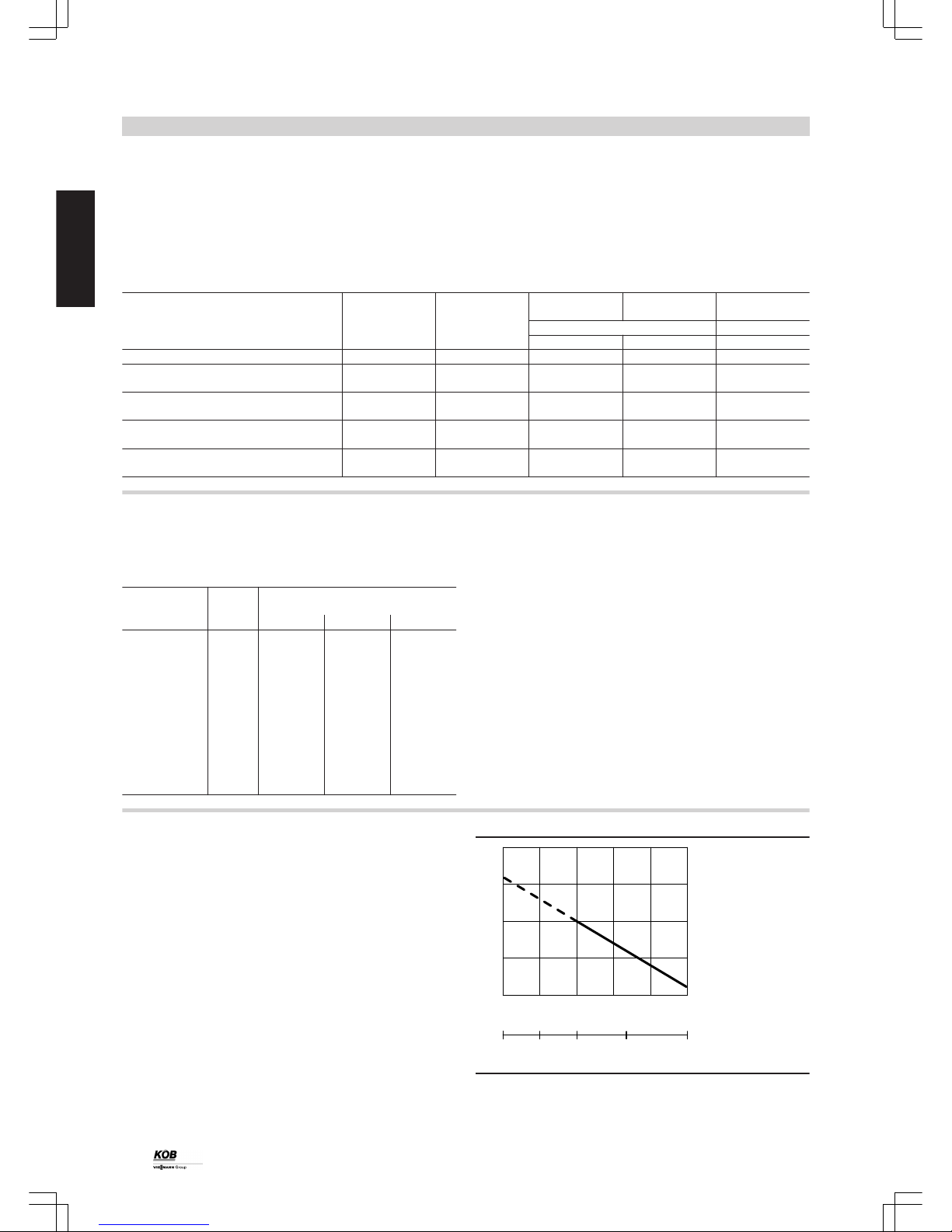
1.1 Principles of log combustion for generating heat
Units of measurement for wood fuel
The units of measurement commonly used in forestry and the timber
industry for wood fuel are solid measures of timber (smt) and stacked
cubic metres (stcm). The solid measure of timber (smt) describes
1 m3 of solid timber mass in the form of assorted round timbers.
The stacked cubic metre (stcm) is a measure for stacked or tipped
wood, measuring a total volume of 1 m3, including air gaps. On average, one solid measure of timber equals 1.4 stacked cubic metres.
Conversion table for assorted common firewood
Unit of measurement Solid measure
of timber (smt)
Stacked cubic
metre (stcm)
Stacked cubic
metre (stcm)
Tipped cubic
metre (tcm)
Tipped cubic
metre (tcm)
Assorted Round timbers Logs
Logs Woodchips
stacked tipped G 50 "medium"
1 smt round timber 1 1.40 1.20 2.00 3.00
1 stcm logs
1 m long, stacked
0.70 1.00 0.80 1.40 (2.10)
1 stcm logs
split, stacked
0.85 1.20 1.00 1.70
1 tcm logs
split, tipped
0.50 0.70 0.60 1.00
1 tcm (forest) - woodchips
G 50 "medium"
0.33 (0.50) 1.00
Calorific and emission values
Timber is a renewable fuel. During combustion, on average approx.
4.0 kWh/kg units of energy are released.
The table shows the net calorific value of various types of timber with
a water content of 20 %.
Type of timber Density Net calorific value (approx. at 20 %
water content)
kg/m
3
kWh/smt kWh/stcm kWh/kg
Conifers
Spruce 430 2100 1500 4.0
Fir 420 2200 1550 4.2
Pine 510 2600 1800 4.1
Larch 545 2700 1900 4.0
Deciduous
Birch 580 2900 2000 4.1
Elm 620 3000 2100 3.9
Beech 650 3100 2200 3.8
Ash 650 3100 2200 3.8
Oak 630 3100 2200 4.0
Hornbeam 720 3300 2300 3.7
1 litre of fuel oil can be replaced by 3 kg of timber, assuming typical
efficiency. A stacked cubic metre (stcm) of beech corresponds to the
energy of approx. 200 litres of fuel oil or 200 m3 of natural gas. Therefore burning wood contributes to the preservation of the finite reserves
of oil and gas.
Timber has a generally neutral CO2 balance, as the CO2 created during
combustion is immediately reabsorbed into the photosynthesis cycle
and therefore contributes to the formation of new biomass. Another
environmental aspect is the fact that timber contains hardly any sulphur, therefore almost no sulphur dioxide is created during combustion.
Influence of moisture on the net calorific value
The water content of timber substantially influences its net calorific
value. The more water timber contains, the lower its net calorific value,
since the water evaporates during combustion and consumes energy
in the process.
Two measures are used to specify the water content:
■ Water content
The water content of timber is its water mass as a percentage of the
total timber mass.
■ Timber moisture level
The timber moisture level (hereafter referred to as moisture or moisture level) is the water mass as a percentage of the total timber mass
excluding water.
The graph shows the relationship between the water content and the
moisture level, as well as the dependency of the net calorific value.
11
2
3
4
5
0 10 20 30 40 50
Water content in %
0 25 50 100
Moisture level in %
Calorific value kWh/kg
Freshly cut timber has a moisture level of 100 %. During storage over
one summer, this moisture level reduces to approx. 40 %. During storage over several years, this moisture level reduces to approx. 25 %.
Principles of wood combustion for generating heat
4
PYROMAT ECO
1
5822 508 GB
Page 5

The graph shows the dependency of the net calorific value on the water
content, using spruce as an example. With a water content of 20 %
(moisture level 25 %), the net calorific value is 4.0 kWh/kg.
The net calorific value of timber stored over several years is approx.
twice that of freshly cut timber.
Storage
Not only is the combustion of moist wood uneconomical, it also leads
to low combustion temperatures and high emissions plus tar deposits
inside the chimney.
Information on storing firewood
■ Split round logs from a diameter of 10 cm upwards. Enlarging the
surface area enables the wood gases to be expelled more quickly
and simply. The drying process is also accelerated during storage.
■ Stack the logs in a ventilated and preferably sunny spot underneath
a rain canopy.
■ Stack the logs with generous air gaps to enable the flowing air to
carry off the dissipating moisture.
■ A hollow should be created underneath the wood pile (e.g. in the
form of support timbers) to allow moist air to escape downwards.
■ Never store freshly cut wood in a cellar, as air and sunshine are
required for drying. However, dried wood can be stored in a well
ventilated cellar.
1.2 Minimum wood fuel requirements
Wood remnants, coarse woodchips and compressed shavings can be
used in the Pyromat Eco. The Pyromat Eco is ideal for the combustion
of logs. The wood should have an edge length between 45 and 50 cm
or up to 100 cm (depending on the boiler type: boilers for 50 cm logs
or 100 cm logs). The rated wood boiler output will only be achieved
with dry wood with maximum 20 % water content (air-dried wood).
Wood of poorer quality and higher moisture content also reduces the
rated output and the length of combustion.
When using softwood (e.g. spruce), note that the energy per volume
unit is lower than with hardwood (e.g. beech). Softwood is therefore
suitable for "initial heat-up" - however, its use shortens the intervals
between recharging considerably and increases the volume to be used
(up to 44 %). Observe the requirements specified in the next chapter
relating to non-combustible substances and their limits for warranty
period claims. Deviations are only possible through written, systemspecific manufacturer declarations.
Substances
When procuring wood for combustion in a Pyromat Eco, foreign matter
(e.g. stones, metal parts, brick, plastics, etc.) should be avoided. This
changes the composition of the fuel and therefore the critical parameters of the combustion process.
The values (per kg of dry fuel) of the non-combustible substances (ash
at an analysis temperature of 815 °C) must not fall below or exceed
the following limits:
Limit Comparison with natural wood from forests
Chlorine Cl mg/kg max. 300 10
Sulphur S mg/kg max. 1000 120
Total Cl, S mg/kg max. 1000 130
Ash content total g/kg max. 15.0 5.0
Alkali oxides in the ash (K2O and Na2O) g/kg max. 1.0 0.35
SB start of ash sintering °C min. 1000 approx. 1200
A consequence of the above limits being exceeded is a shortened
service life of the combustion chamber and the wood boiler. The maintenance work is also increased and the maintenance intervals are
shortened.
The proportion of dust-like and fine-grained materials should also be
minimised (acc. to ÖNORM M 7133).
Origin, treatment and storage
Depending on the origin, wood can be natural wood (e.g. forest wood
and waste from sawmills), residual wood from wood processing plants
or waste wood (building rubble, furniture). The wood must be obtained
and, if required, cut to the desired size and treated with regard to foreign matter. In addition to the requirement to adhere to ÖNorm M 7133,
a max. proportion of 5 % outliers in the fuel should be observed.
The length of the outliers must not exceed 16 cm (with a cross-section
of max. 5 cm²). The surface of the fuels should be roughened where
possible (e.g. through shredder, etc.). When using briquettes, ensure
compression is matched to charging. The maximum diameter is 60
mm.
Size of the woodchips
The Pyromat Eco is also suitable for the combustion of coarse woodchips. To prevent increased maintenance work, appropriate coarse woodchips in accordance with ÖNorm M 7133 should be used.
Principles of wood combustion for generating heat
(cont.)
PYROMAT ECO
5
5822 508 GB
1
Page 6

Further information
Ash and cleaning
Natural wood without bark has a percentage of ash less than 0.5 % of
the supplied fuel mass. All information regarding cleaning work is
based on natural wood with attached bark and an ash percentage of
0.8 %. The cleaning and maintenance work for other wood fuels should
be matched according to the quantity, the specific weight and the ash
characteristics.
Changing fuels
Frequent and intensive changes in fuel quality, e.g. bulk density, water
content, dust proportion and ash content, can require a manual adjustment of the combustion system parameters.
Non-wood fuels made from biomass
Non-wood fuels made from biomass such as needles, leaves, cereals,
straw, husks, fruit stones, etc. are generally unsuitable as fuel for faultfree operation, and are therefore not permissible.
The fuel properties (elementary composition, ash sintering point, etc.)
deviate from wood, in some cases considerably. Combustion in a
Pyromat Eco can lead to an impairment of the combustion characteristics and increased stress on the fireclay lining and the heat
exchanger surfaces. Warranty claims can therefore only be asserted
when using permissible fuels.
Wood fuels: regulations and standards
Germany Revised first version of BImSchV dated 22.03.2010
Austria FAV dated 18.11.1997 "Ordinance for Combustion Systems" § 3.(1) 3. Solid fuels Solid fuels
Switzerland Clean air regulations LRV dated 16.12.1985 (dated 28.03.2000)
ÖNORM M 7133 Woodchips for energy purposes (1998)
EN 303-5 Boilers for solid fuels, table 8 "Test fuels"
CEN/TS 14961 Solid biofuels
Principles of wood combustion for generating heat
(cont.)
6
PYROMAT ECO
1
5822 508 GB
Page 7
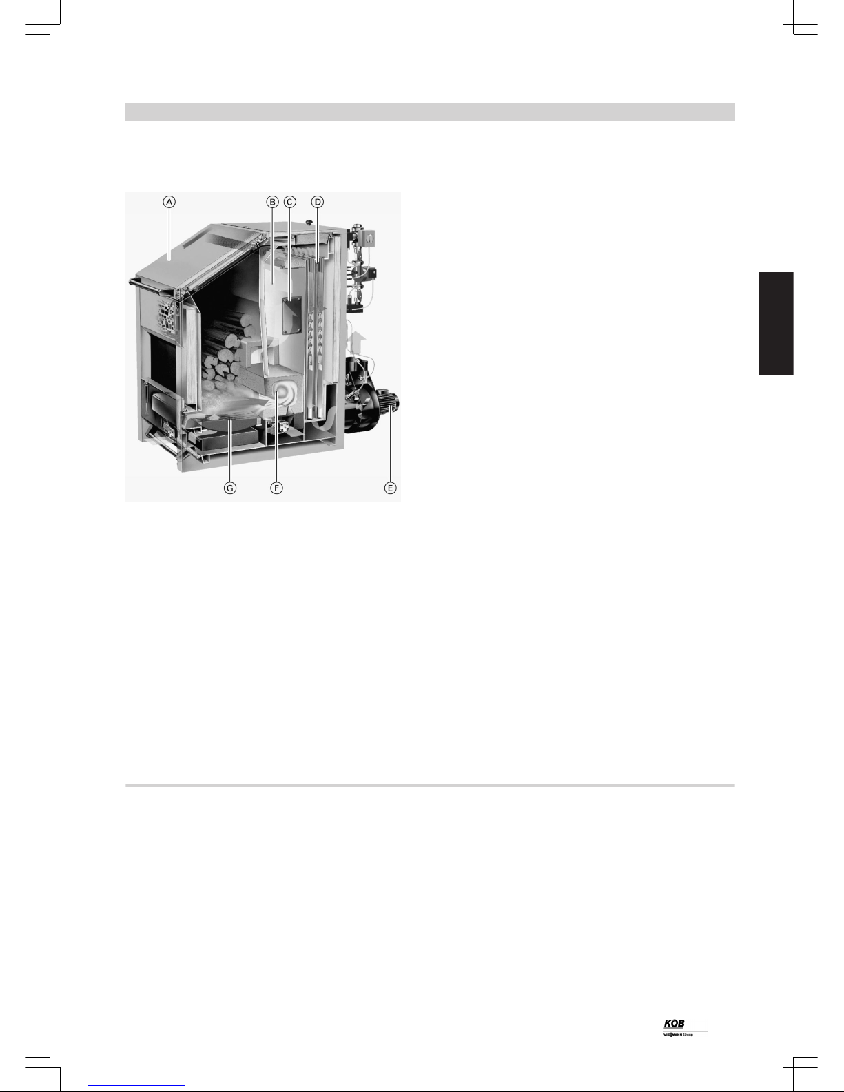
2.1 Product description
Benefits
A
Upper charging door with a large hopper, with an extended downward taper
B
Secondary combustion chamber for complete burnout
C
Maintenance cover for secondary combustion chamber with trolley for burner support
D
Vertical tubular heat exchanger for optimum heat transfer
E
Flue gas fan, solid version for long service life; strong underpressure for high safety and simple recharging; noise optimised; low
power consumption
F
Patented combustion chamber made from refractory concrete for
degasification
G
Solid cast grate for hot degasification zone and long service life
The Pyromat Eco was developed specifically for the combustion of
logs and represents state of the art combustion technology.
The Pyromat Eco log boiler has already proven itself thousands of
times. Charging from the top offers easy handling, control via the
Lambda probe guarantees low emissions, and the integral heat management ensures maximum convenience.
Clean and efficient combustion
The microprocessor-controlled Ecotronic captures all details relevant
for the operation and regulates the amount of heat and its demand. As
a result, the boiler system is monitored permanently in all operating
phases, from heat-up, operation under load and recharging, right
through to burnout, and is held – via its motorised air dampers – within
its optimum operating range. Through this, clean and efficient combustion is guaranteed.
Large hopper for combustion lasting several days
The Pyromat Eco offers the greatest operating convenience when
heating with logs due to its large charging chute. Log boilers in the
output range 40 to 95 kW can operate with logs of 0.5 m in length; in
the range 85 to 170 kW, the hopper width increases to 1080 mm,
ensuring convenient charging even with logs of 1 m length.
With oil burner connection
The Pyromat Eco is approved as oil boiler compliant with EN standard;
the necessary connections have already been prepared. Fitting an oil
burner may, for example, help to bridge holiday times when manual
charging with logs is not feasible.
The Pyromat Eco is particularly suitable for the combustion of logs,
wood briquettes and wood remnants, either loose or in pieces.
The Pyromat Eco boiler system has been tested in accordance with
the latest quality criteria to EN 303-5 "Boilers for solid fuels", and can
be brought into circulation with CE designation (RL 98/38/EC etc.) and
VKF approval.
Benefits at a glance
■ Log boiler for logs of 0.5 and 1 m length with high operating convenience through charging from the top
■ For the fuels: logs, wood briquettes and wood remnants, either loose
or in pieces
■ Large hopper capacity (185 to 500 litres) for combustion lasting several days
■ Fully wired
■ Proven induced draught fan for quiet operation and a long service
life
■ No draught controller or limiter required
■ Constantly regulating air damper with heat-up and burnout optimisation
■ Accurate temperature stratification of a DHW cylinder by means of
a cylinder heating control valve – no possible irritation of the cylinder
stratification through the return (option)
■ Return temperature raising facility with buffer control valve, fully
assembled
■ Not sensitive to foreign bodies (nails, screws etc.)
■ Integral buffer heating management
■ Lambda probe control
Pyromat Eco
PYROMAT ECO
7
5822 508 GB
2
Page 8

Delivered condition
Boiler with the following components:
■ Fully wired flue gas fan with flue gas temperature sensor and
Lambda probe
■ Fully assembled return temperature raising facility
■ Buffer control valve
■ Ash box, stoking and cleaning
device
■ Fully assembled casing panels
■ Ecotronic
– Electronic module integrated in the boiler, incl. high limit safety cut-
out (STB)
– Programming module
■ 13 buttons for operating external controllers
■ 3 sensors KTY incl. sensor well (R ½, 280 mm long) wired jointly to
connector
Note
Data cable for connecting to the programming module (separate
item), see page 12
Fully assembled return temperature raising facility
The return temperature raising facility is fully fitted to the connection
flange. It comprises a boiler pump, boiler control valve, and flow and
return temperature sensors, incl. the connecting pieces. The pump is
located between two shut-off valves.
Pyromat Eco
(cont.)
8
PYROMAT ECO
2
5822 508 GB
Page 9

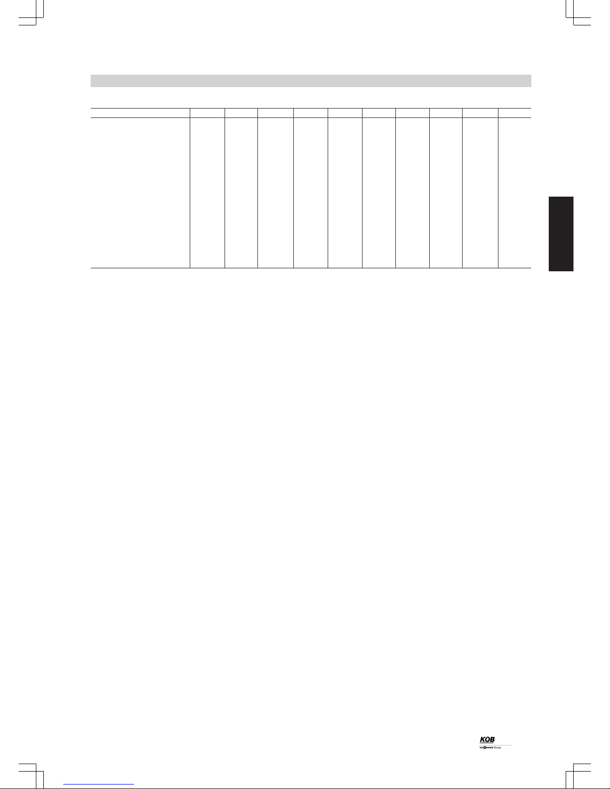
2.2 Specification
Specification
Pyromat Eco... 35 45 55 65 75 85 61 81 101 151
Rated output kW 40 50 60 75 80 95 85 100 120 170
Min. heat consumption, wood kW 35 38 45 55 60 75 60 75 90 110
Max. log length m 0.5 0.5 0.5 0.5 0.5 0.5 1 1 1 1
Hopper capacity l 185 185 255 255 255 255 375 375 500 500
Boiler water content l 130 130 170 170 210 210 230 230 300 300
Boiler weight (dry) kg 750 760 920 935 1040 1065 1300 1320 1680 1720
Test pressure bar 6 6 6 6 6 6 6 6 6 6
Max. operating pressure bar 3 3 3 3 3 3 3 3 3 3
Max. boiler water temperature, wood °C 100 100 100 100 100 100 100 100 100 100
Min. return temperature °C 70 70 70 70 70 70 70 70 70 70
Water-side pressure drop (diff. 10 K) mbar 32 32 62 62 98 98 56 56 112 112
Water-side pressure drop (diff. 20 K) mbar 8 8 16 16 25 25 14 14 28 28
Thermally activated safety valve: min.
flow rate at 2.5 bar
kg/h 2000 2000 2800 2800 3500 3500 3500 3500 5500 5500
Boiler efficiency
(rated output, wood)
% 92 92 92 92 92 92 92 92 92 92
Flue gas temperature (rated output,
wood)
°C 180 180 180 180 180 180 180 180 180 180
Flue gas mass flow rate
(rated output, wood)
g/s 30.4 35.2 44 56 60 68 58.4 72 88 108
Max. draught, wood
*1
Pa 25 25 25 25 25 25 25 25 25 25
Rated output, oil kW 35 38 45 55 60 75 60 75 90 110
Boiler efficiency
(rated output, oil)
% 87 87 87 87 87 87 87 87 87 87
Flue gas temperature
(rated output, oil)
°C 168 168 168 168 170 170 172 172 168 168
Required chimney draught
*2
Pa ±0 ±0 ±0 ±0 ±0 ±0 ±0 ±0 ±0 ±0
Electrical output, flue gas fan kW 0.08 0.08 0.08 0.08 0.15 0.15 0.15 0.15 0.25 0.25
Return temperature raising facility
with buffer control valve
Boiler pump Wilo Type RS 30/6 TOP-S 30/7 EM TOP-S 40/7 EM
Electrical output, pump W 46 - 93 85 - 195 220 - 390
Pump output
m3/h
at
mWC
2.5 at 6.5 7.5 at 7.0 16.5 at 7.0
Boiler control valve Siemens Type VXG
48.32
VXG
48.32
VXG
48.32
VXG
48.32
VXG
48.40
VXG
48.40
VXG
48.40
VXG
48.40
VXG
48.40
VXG
48.40
Drive, boiler control valve Siemens SQS
35.00
SQS
35.00
SQS
35.00
SQS
35.00
SQS
35.00
SQS
35.00
SQS
35.00
SQS
35.00
SQS
35.00
SQS
35.00
Weight, return temperature raising
facility with buffer control valve
kg 14 14 16 16 20 20 20 20 40 40
Cylinder control valve Siemens Type VXG
48.40
VXG
48.40
VXG
48.40
VXG
48.40
VXG
48.40
VXG
48.40
VXG
48.40
VXG
48.40
VBF
21.50
VBF
21.50
Drive, cylinder control valve SQS
35.00
SQS
35.00
SQS
35.00
SQS
35.00
SQS
35.00
SQS
35.00
SQS
35.00
SQS
35.00
SQK33SQK 33
Weight, cylinder control valve kg 2.5 2.5 2.5 2.5 2.5 2.5 2.5 2.5 6.9 6.9
Connections
Flue gas connection DN
200*3200*3200*3200
*3
200 200 200 200 250 250
Drain R ½ ½ ½ ½ ½ ½ ½ ½ ½ ½
Boiler return R 1¼ 1¼ 1¼ 1¼ 1½ 1½ 1½ 1½ 1½ 1½
Boiler flow R 1¼ 1¼ 1¼ 1¼ 1½ 1½ 1½ 1½ 1½ 1½
Safety connection R ½ ½ ½ ½ ½ ½ ½ ½ ½ ½
Temperature sensor R ½ ½ ½ ½ ½ ½ ½ ½ ½ ½
Sight glass R 1 1 1 1 1 1 1 1 1 1
*1
Maximum overpressure in the start phase (chimney cold) in the flue pipe downstream of the flue gas fan
*2
No draught limiter required
*3
Reduction to DN 160 or DN 180 possible
Pyromat Eco
(cont.)
PYROMAT ECO
9
5822 508 GB
2
Page 10
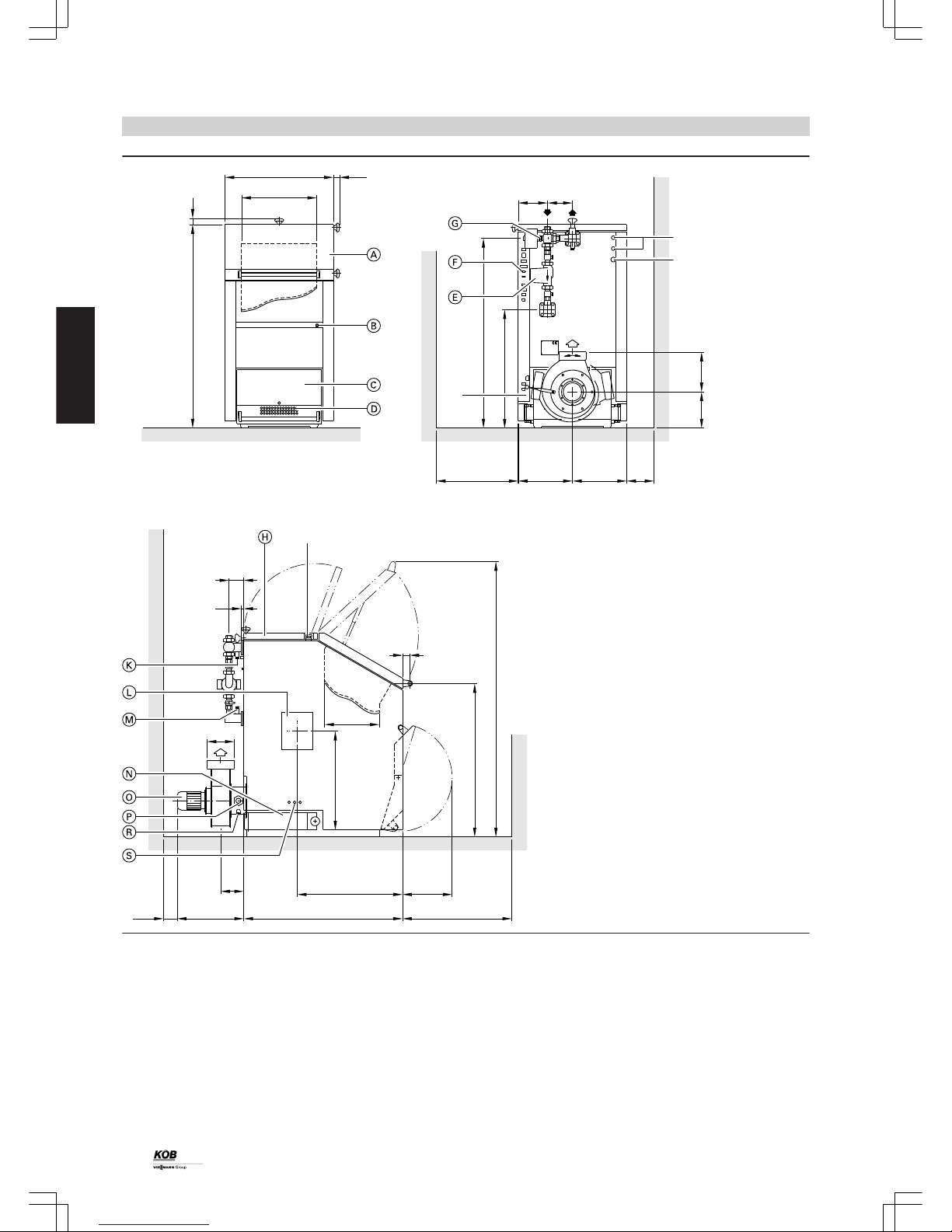
a
45
b 45
c
e
d 183
f
g = = h
265 293
m
1134
k
l
108
20
80
AGA
≥100
n
o
p
q 365
≥800
SA
TS
SG
KR KV
E
AGA Flue gas connection
E Drain
KR Boiler return
KV Boiler flow
SA Safety connection for thermally activated safety valve
SG Sight glass (transportation hook)
TS Temperature sensor for thermally activated safety valve
A
Hopper door
B
Boiler module with high limit safety cut-out
C
Ash chamber door
D
Primary air damper with servomotor
E
Boiler pump
F
Sockets for electrical connection
G
Boiler control valve with servomotor
H
Cleaning door, top
K
Flow temperature sensor
L
Flange for fitting the burner trolley, maintenance cover, combustion chamber (on both sides)
M
Return temperature sensor
N
Cleaning door, bottom
O
Motor, flue gas fan
P
Lambda probe
R
Flue gas temperature sensor
S
Secondary air damper with servomotor
Pyromat Eco
(cont.)
10
PYROMAT ECO
2
5822 508 GB
Page 11
Dimensions
Pyromat Eco ... 35 45 55 65 75 85 61 81 101 151
a mm 1433 1433 1490 1490 1490 1490 1433 1433 1490 1490
b mm 795 795 795 795 795 795 1324 1324 1324 1324
b without thermal
insulation
mm 686 686 686 686 686 686 1246 1246 1246 1246
c mm 550 550 550 550 550 550 1080 1080 1080 1080
d mm 214 214 214 214 214 214 480 480 480 480
e mm 1331 1331 1389 1389 1386 1386 1328 1328 1386 1386
f mm 811 811 869 869 693 693 635 635 636 636
g mm
≥ 600 ≥ 600 ≥ 600 ≥ 600 ≥ 600 ≥ 600 ≥ 800 ≥ 800 ≥ 800 ≥ 800
h mm
≥ 200 ≥ 200 ≥ 200 ≥ 200 ≥ 200 ≥ 200 ≥ 400 ≥ 400 ≥ 400 ≥ 400
k mm 770 770 773 773 813 813 770 770 876 876
l mm 300 300 400 400 475 475 300 300 400 400
m mm 1892 1892 2012 2012 2012 2012 1892 1892 2012 2012
n mm 500 500 500 500 630 630 630 630 630 630
o mm 175 175 175 175 300 300 300 300 300 300
p mm 958 958 1163 1163 1313 1313 1018 1018 1353 1353
q mm 647 647 769 769 842 842 631 631 820 820
Pyromat Eco
(cont.)
PYROMAT ECO
11
5822 508 GB
2
Page 12
3.1 Specification for Ecotronic
Structure and function
Modular structure
The Ecotronic system control unit is a decentralised microprocessor
system (CAN BUS). To control the boiler system, the Ecotronic comprises a module (PCB) integrated into the boiler, and the programming
module. Three-sensor cylinder management is part of the standard
Ecotronic version.
Controller modules can be added to the Ecotronic (modular structure).
It is therefore possible to extend operation individually according to
customer requirements.
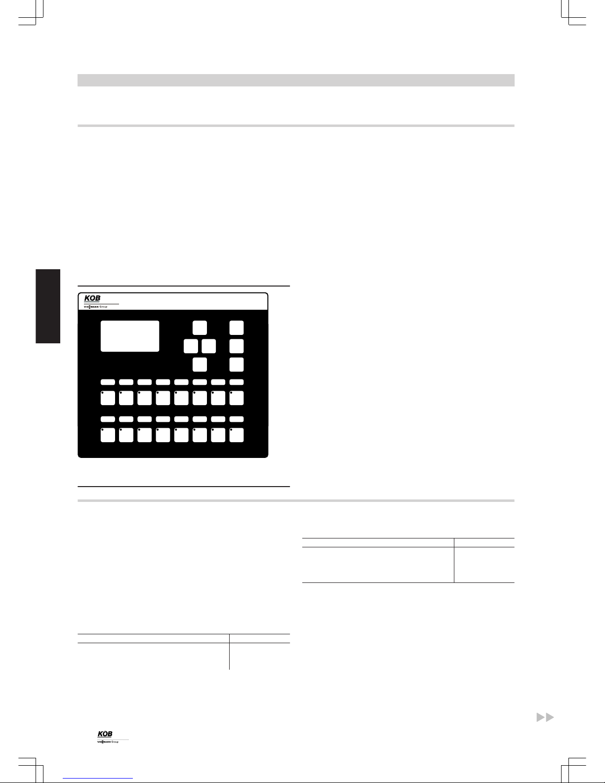
Programming module
The programming module is included in the standard delivery for the
boiler and is used to operate the heating system. Preferably install on
a wall and connect to boiler via a data cable.
The backlit screen offers an extensive text display.
F10F9
F12
F11
F13
F14
F15
F16
>
F2F1
F4
F3
<
>
F5
F6
>
F7
-
OK
F8
+
Ecotronic
The programming module
Functions
■ Output and cylinder control is carried out by constantly regulating air
dampers with heat-up and burnout optimisation
Rated load: during cylinder heating
Partial load: at the end of the phase of cylinder heating
■ Lambda probe enables efficient combustion control and maximum
efficiency
■ Keeping up the return temperature with the boiler control valve
■ Release of the complete heating output during the start phase of the
boiler to the consumers (no output transfer into cylinder via return)
■ Accurate temperature stratification of the cylinder with the cylinder
control valve
■ Safe recharging with wood through the closing of the primary air
damper during recharging
■ Use of the residual boiler heat after burnout
■ Supporting auxiliary and service functions
■ Control of an additional oil burner
■ Protection against overheating through heat transfer to the buffer
cylinder, shutting down the flue gas fan and closing the air dampers.
3.2 Accessories for Ecotronic
Modules and data cables
The standard Ecotronic version can be customised with additional
controller modules or controllers and data cables. Additional heat
sources, heat consumers or DHW cylinders can be incorporated into
the control system with/without solar heating circuit backup.
Data cables
The data cable connects the individual modules (boiler module, programming module, controller module) to the overall system control
unit. Data cables can be connected together (max. 2 cables). The total
length of all CAN BUS cables must not exceed 200 m.
Description Part no.
Data cable with connector 10.0 m standard 7387 587
Data cable with connector 2.0 m 7387 858
Data cable with connector 5.0 m 7388 000
Description Part no.
Data cable with connector 20.0 m 7388 025
Data cable with connector 40.0 m 7387 588
Data cable with connector 80.0 m 7387 972
Data cable with Y-distributor 7387 948
Controller module
The controller module is supplied in a plastic casing (length 325 mm,
height 195 mm, depth 75 mm) incl. outside temperature sensor
(QAC 31).
The control keys for the controller module are available at the programming module and are enabled according to the number of controllers. The controller module has four controller outputs and seven
sensor inputs.
Control unit
12
PYROMAT ECO
3
5822 508 GB
Page 13

Optional combinations
Additional controller modules (ECO-RM-00) for an additional charge
1 controller module 2 controller modules 3 controller modules
Programming module
13 controller keys
Max. 4 controllers and 7 sensors
possible
Max. 8 controllers and 14 sensors
possible
Max. 13 controllers and 21 sensors
possible
Overview: Possible Ecotronic controllers
Controller Part no. Keys Number of control-
lers
Number of sensors
Controller, additional heat sources
Heat source, single 7388 036 1 1 —
Heat source, modulating 7387 859 1 1 1
Heat source, parallel KP2 7387 864 1 2 1
Controller, central heating
Central heating 7379 402 1 1 1
Adjacent building 7387 865 1 2 2
Long-distance line 7379 401 1 1 1
Space heater 7387 825 1 1 1
Room controller QAA 35
*4
7379 405 — — 1
Safety thermostat RAK-TW.1000B
*5
7387 940 — — —
DHW controller
DHW cylinder B1 (without flow control) 7387 853 1 1 1
DHW cylinder B2 (with flow control) 7379 400 1 1 2
DHW circulation 7387 849 1 1 —
Controller, solar
Solar DHW cylinder 7387 818 1 1 2
Solar DHW and central heating 7387 786 1 2 2
Controller, heat source, single
A
Two-way valve
B
Burner
Part no. 7388 036
The additional heat source is switched on automatically after heat is
drawn from the buffer cylinder to cover the heat demand (single operation). Heating of the buffer cylinder is only possible with the Pyromat.
If this is started, the additional heat source switches off and the closed
two-way valve prevents permeation.
Standard delivery:
■ Button, additional heat source
■ Controller output for two-way valve and burner
Note
See hydraulic scheme 40
*4
Only in conjunction with controller for central heating or controller for adjacent building.
*5
For limiting the heating circuit flow temperature.
Control unit
(cont.)
PYROMAT ECO
13
5822 508 GB
3
Page 14
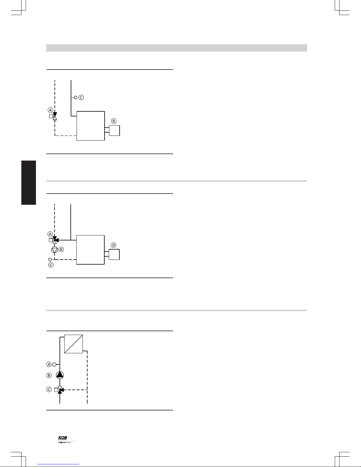
Controller, heat source, single, modulating
A
Two-way valve
B
Burner
C
Contact sensor QAD 21
Part no. 7387 859
The additional heat source is automatically switched on after heat is
drawn from the buffer cylinder to cover the heat demand (single operation). Heating of the buffer cylinder is only possible with the Pyromat Eco. If this is started, the additional heat source switches off and
the closed two-way valve prevents permeation. The boiler water temperature control is modulated to minimum temperature according to
the heat demand.
Standard delivery:
■ Button, additional heat source
■ Controller output for two-way valve and burner
■ Contact sensor QAD 21
Note
See hydraulic scheme 40
Controller, heat source, parallel KP2
A
Mixing valve
B
Pump
C
Contact sensor QAD 21
D
Burner
Part no. 7387 864
The additional heat source is switched on automatically when required.
This may occur after heat is drawn from the buffer cylinder to cover the
entire heat demand (single operation). Otherwise the additional heat
source is used to cover peak heat demand (parallel operation to the
biomass boiler). For parallel operation, a return temperature raising
facility is required for heat transfer, which also ensures that the return
temperature is kept up. On request, the additional heat source can
heat the buffer cylinder (sensor optional).
Standard delivery:
■ Button, additional heat source
■ Controller output for pump, mixing valve and burner
■ Contact sensor QAD 21
Controller, central heating
Heating circuit with mixer
A
Contact sensor QAD 21
B
Pump
C
Mixing valve
Part no. 7379 402
Weather-compensated heating control unit with digital time switch for
setback mode according to individual day and seven-day program,
with pump control unit, frost protection function, eco mode and limited
flow temperature.
Standard delivery:
■ Button, central heating
■ Controller output for pump and mixing valve
■ Contact sensor QAD 21
Control unit
(cont.)
14
PYROMAT ECO
3
5822 508 GB
Page 15

Controller, adjacent building
Heating circuit with mixer and DHW pipe
A
Diverter valve
B
Adjacent building
C
Contact sensor QAD 21
D
Pump
E
Mixing valve
F
Sensor QAZ
Part no. 7387 865
The cable to the adjacent building is controlled with weather compensation via the heating circuit control unit. The DHW cylinder is heated
with the selected maximum flow temperature. For this, the heating
water is diverted to the DHW cylinder via a valve. By means of the time
switch, the DHW cylinder is reheated in the downtimes (setback periods).
Standard delivery:
■ Button, adjacent building
■ Controller output for pump, mixing valve and diverter valve
■ Contact sensor QAD 21
■ Sensor QAZ 21.5220 with sensor well ½" x 200 mm
Room controller QAA 35
Part no. 7379 405
Addition to the controller for central heating and controller for adjacent
building. The room controller can be connected as a remote control
unit and as a room temperature sensor (room temperature compensation).
Standard delivery:
■ Room controller QAA 35
Safety thermostat RAK-TW.1000B
A
Safety thermostat RAK-TW.1000B
Part no. 7387 940
For safe limitation of the flow temperature of a heating circuit.
Standard delivery:
■ Safety thermostat RAK-TW.1000B
Control unit
(cont.)
PYROMAT ECO
15
5822 508 GB
3
Page 16

Controller, long-distance line
A
Sub-distributor
B
Bypass
C
Contact sensor QAD 21
D
Pump
E
Control valve
Part no. 7379 401
A building is supplied with separate heat distribution via a long-distance line.
The long-distance line is controlled upstream according to the demand
of the heating circuits. The heating circuits of the separate heat distribution must be controlled via the Ecotronic.
Standard delivery:
■ Button, long-distance line
■ Controller output for pump and control valve
■ Contact sensor QAD 21
Note
The long-distance line controller module can only be used while Köb
controller modules in the sub-distributor is also being used.
Controller, space heater
A
Pump
B
Mixing valve
C
Contact sensor QAD 21
Part no. 7387 825
The space heaters are supplied by the boiler cylinder system with
maximum flow temperature.
The switching of the fan is carried out by on-site switches or controllers.
The flow rate of the heating water is controlled via the return temperature and matched to the output of the space heater (flow control). This
results in optimum cylinder stratification with sustained high temperature at the cylinder flow. The heating periods (individual day and
seven-day program) can be adjusted via the integrated time switch.
Standard delivery:
■ Button, space heater assembly
■ Controller output for pump and mixing valve
■ Contact sensor QAD 21
■ Restrictor, bypass
Control unit
(cont.)
16
PYROMAT ECO
3
5822 508 GB
Page 17

Controller, DHW cylinder B1
A
Pump
B
Two-way valve
C
Sensor QAZ 21.5220
Part no. 7387 853
When the temperature of the DHW falls, the DHW is reheated via the
internal indirect coil by the boiler or the buffer cylinder. This is dependent on a corresponding difference in temperature (either differential
temperature or fixed temperature control unit).
The heating periods (individual day and seven-day program) can be
adjusted via the integrated time switch.
Standard delivery:
■ Button, DHW cylinder
■ Controller output for pump and ball valve
■ Sensor QAZ21.5220 with sensor well ½" x 200 mm
Controller, DHW cylinder B2
T
A
Pump
B
Control valve
C
Sensor QAZ 21.5220
D
Contact sensor QAD 21
Part no. 7379 400
When the temperature of the DHW falls, the DHW is reheated via the
internal indirect coil by the boiler or the buffer cylinder. This is dependent on a corresponding difference in temperature (either differential
temperature or fixed temperature control unit).
The flow rate of the heating water is controlled via the return temperature (flow control). This results in optimum buffer cylinder stratification
with sustained high temperature at the buffer cylinder flow. The heating
periods (individual day and seven-day program) can be adjusted via
the integrated time switch.
Standard delivery:
■ Button, DHW cylinder
■ Controller output for pump and control valve
■ Contact sensor QAD 21
■ Sensor QAZ 21.5220 with sensor well ½" x 200 mm
Control unit
(cont.)
PYROMAT ECO
17
5822 508 GB
3
Page 18

Controller, DHW circulation
T
A
Pump
Part no. 7387 849
The DHW circulation periods (individual day and seven-day program)
can be adjusted via the integral time switch.
The start-up duration of the DHW circulation pump can be adjusted via
timed cycling.
Standard delivery:
■ Button, DHW circulation
■ Controller output for pump
Controller, solar DHW cylinder
T
T
T
KW
WW
KW
HV
HR
RL
VL
HR Heating return
HV Heating flow
KW Cold water
RL Return (solar)
VL Flow (solar)
WW DHW
A
Solar collector
B
Collector temperature sensor
C
Solar station with solar circuit pump
D
Thermostatic water mixer
E
Cylinder temperature sensor QAZ 21.5220
Part no. 7387 818
Use for single solar thermal system as a single circuit control unit for
heating the DHW in the solar DHW cylinder.
If the temperature of the DHW (in the lower section of the DHW cylinder) falls below the collector temperature, the DHW is heated by the
solar collector (adjustable differential temperature: 2 - 20 °C).
Note
The controller for the solar DHW cylinder can only be used in conjunction with a controller for a DHW cylinder (B1 or B2).
Run-on time of the solar circuit pump adjustable from 0 to 120 s (subject to line length).
Maximum DHW temperature adjustable from 20 to 90 °C.
Safety: the solar circuit pump switches off at 140 °C collector temperature; restarts at 120 °C.
Standard delivery:
■ Button, solar
■ Collector temperature sensor PT-1000
■ Cylinder temperature sensor QAZ 21.5220
■ Controller output for the solar circuit pump
Control unit
(cont.)
18
PYROMAT ECO
3
5822 508 GB
Page 19

Controller, solar/DHW and central heating
Part no. 7387 786
Use for a larger solar thermal system for heating the DHW in the solar
DHW cylinder and for heat supply to the heating cylinder as a threecircuit control unit.
The first circuit is used to heat the DHW, the second heats the heating
cylinder back/bottom and the third heats the heating cylinder front/top.
The heating cylinder is heated with an external plate heat exchanger.
Changing over from the DHW cylinder to the heating cylinder starts the
secondary pump. This then operates with the solar circuit pump. For
optimum functioning, the flow rate in the secondary circuit must be
matched to the primary circuit (e.g. with flow meter in the primary and
secondary circuits).
Differential temperature, collector/DHW 2-20 °C.
The following differential temperatures are freely adjustable:
differential temperature, collector/cylinder back/bottom 2-20 °C.
Note
Controller, solar/DHW and central heating can only be used in conjunction with a controller for a DHW cylinder (B1 or B2).
Run-on time of the solar circuit pump adjustable from 0-120 s (subject
to line length).
Shutdown safety:
■ at 140 °C collector temperature
■ at 95 °C cylinder temperature
Optimised DHW priority (either absolute or no DHW priority).
Cylinder heating with stratification in accordance with the cylinder temperatures via a charging valve for the cylinder front/back.
Standard delivery:
■ Button, solar
■ Collector temperature sensor PT-1000
■ Cylinder temperature sensor QAZ 21.5220
■ Controller output for the solar circuit pump
■ Controller output, charging valve, DHW cylinder
■ Controller output for secondary pump
■ Controller output, charging valve, cylinder back/cylinder front
Key to the schemes on pages 20 and 21
KW Cold water
WW Domestic hot water
A
Solar collector
B
Solar station with solar circuit pump
C
Thermostatic water mixer
D
Plate heat exchanger
E
Charging valve, DHW cylinder/buffer cylinder
F
Secondary pump
G
Charging valve, buffer cylinder front/back
H
Wood boiler
K
Example: two heating water buffer cylinders in series
L
Example: three heating water buffer cylinders in series
Control unit
(cont.)
PYROMAT ECO
19
5822 508 GB
3
Page 20

KW
WW
A
B
C
D
F
G
H
K
--B28.1--
--B28.2--
--B28.3--
E
Return
Flow
Control unit
(cont.)
20
PYROMAT ECO
3
5822 508 GB
Page 21

KW
WW
A
B
C
D
E
F
G
H
L
Return
Flow
Control unit
(cont.)
PYROMAT ECO
21
5822 508 GB
3
Page 22

Visualisation
Part no. 7387 780
With a data cable (max. 30 m) to the PC, all data is fed via the serial
interface RS 232 from the programming module to the PC. The current
operating data for the boiler system is displayed visually on a function
screen. This visualisation gives all options for inputting values and
functions and reading out the operating conditions (exception: "Start
boiler"). All operating data is archived cyclically and can be evaluated
graphically in an extremely simple way.
The PC and required data cables are not included in the standard
delivery.
Standard delivery:
■ Visualisation software and installation instructions
Note
Requirements for on-site PC:
■ Operating system: Windows 98/2000/XP
■ At least 50 MB free hard disk memory
■ At least 128 MB RAM
■ One free serial interface per boiler
Visualisation, additional functions
Part no. 7387 821
Extension of visualisation with the functions of additionally enabled
buttons (from F4).
Further functions include each heating controller (for heat source, heat
consumer, solar) and automatic charging (if available). Every button
function is shown on a separate function screen.
There are options for entering values, reading out operating conditions
and archiving.
Surcharge per additionally enabled button on the programming module.
Standard delivery:
■ Extension with visualisation software
Note
All data from controllers used can be visualised. An additional function
must be used for each controller.
3.3 Routing the CAN BUS
Ecotronic with heating controllers:
The Ecotronic can be extended with many heating controllers (heat
consumers, additional heat sources, solar energy) (see accessories
for Ecotronic, page 12).
The operation of the external controller is carried out at the programming module of the boiler system.
Each controller is operated with a separate button.
The Ecotronic can be extended as follows:
1. Low-cost solution for a small system with:
■ Programming module for external controller (art. no. ECO-BM-00)
■ Max. 3 controllers (see page 13 onwards)
2. Finished solution for complex systems with:
■ Controller module (art. no. ECO-RM-00)
■ With additional controller modules, up to 13 controllers can be
integrated into the Ecotronic (see page 13 onwards)
Control unit
(cont.)
22
PYROMAT ECO
3
5822 508 GB
Page 23

A
2
3
FG
CAN
CAN
D
B C
--B28.1----B28.2--
--B28.3--
1
--Y28--
--B1-- --B26--
--M13--
--M13.2--
--M13--
--B20-- --B20.1--
--M20--
--Y20--
--M1--
--N21.1--
M17
A
Pyromat Eco
B
Programming module
C
Controller module (1 to 3 controller modules possible)
D
Heat consumer (heating circuits)
F
Buffer cylinder 1
G
Buffer cylinder 2
Heating water buffer cylinder, see page 24 and 38.
DHW cylinder, see page 26.
Visualisation with PC (additional charge), see page 22.
Control unit
(cont.)
PYROMAT ECO
23
5822 508 GB
3
Page 24

4.1 Specification, buffer cylinder
Buffer cylinder HPM
Buffer cylinder without thermal insulation for a wood combustion system with a maximum boiler output of up to 150 kW.
Version:
■ Steel S 235 JRG2, untreated inside, anti-rust coating outside
■ Operating pressure: max. 3.0 bar; test pressure: 4.5 bar
■ Connections: 8 female connections R 1½, 4 female connections
R ½, 1 sensor pipe 14 x 1.5 mm, 1 female connection top R 1¼
Flexible foam insulation to buffer cylinder HPM
The insulation is made from 100 mm thick flexible PUR foam elements
with polystyrene casing.
Fire safety category B3.
Note
Delivery is ex-stock.
Alternative cylinder sizes and insulation types on request.
e
a
b
c
d
03
f
01
01
01
01
01
01
01
01
02
02
02
02
01
02
1
4
o
k
l
m
n
g
h
Part no. buffer cylinder (HPM-) 7424 130 7424 131 7424 132 7424 133 7424 134 7424 135
Part no. flexible foam insulation
(HPM-)
7424 136 7424 137 7424 138 7424 139 7424 140 7424 141
Capacity l 1000 1250 1500 2000 2500 3000
Weight kg 170 176 185 211 260 300
Dimensions
Height when tilted mm 2080 2070 2200 2410 2375 2780
a mm 310 310 380 320 535 380
b mm 745 745 825 900 975 1020
c mm 1250 1250 1350 1490 1415 1680
d mm 1710 1710 1760 2020 1855 2330
e mm 1993 1948 2098 2308 2217 2655
f Total height mm 2043 1998 2148 2358 2267 2705
g Diameter without
insulation
mm 790 950 1000 1100 1250 1250
h Diameter with insula-
tion
mm 990 1150 1200 1300 1450 1450
Heating water buffer cylinder
24
PYROMAT ECO
4
5822 508 GB
Page 25

Part no. buffer cylinder (HPM-) 7424 130 7424 131 7424 132 7424 133 7424 134 7424 135
Part no. flexible foam insulation
(HPM-)
7424 136 7424 137 7424 138 7424 139 7424 140 7424 141
Connections
k 50° 50° 50° 50° 50° 50°
l 50° 50° 50° 50° 50° 50°
m 28.2° 31.9° 32.8° 34.3° 36.2° 36.3°
n 70° 70° 70° 70° 70° 70°
o Length of female con-
nections
mm 100 100 100 100 100 100
01 Female connections,
flow/return
R 1½ 1½ 1½ 1½ 1½ 1½
02 Female connections,
sensor
R ½ ½ ½ ½ ½ ½
03 Female connection,
top
R 1¼ 1¼ 1¼ 1¼ 1¼ 1¼
04 Sensor pipe Ø14xL1400 Ø14xL1400 Ø14xL1400 Ø14xL1700 Ø14xL1250 Ø14xL1700
Heating water buffer cylinder
(cont.)
PYROMAT ECO
25
5822 508 GB
4
Page 26

5.1 Specification, DHW cylinder
DHW cylinder, enamel
Combi cylinder with smooth tube internal indirect coils for connecting to the central heating. The inside has a double enamel coating and a
magnesium anode offers additional corrosion protection. On the outside, the DHW cylinder is insulated with 50 mm rigid PUR foam, and has
optimum thermal insulation through a plastic jacket.
The DHW cylinders, type WSF-E800/1000, are thermally insulated with 90 mm rigid PUR foam shells with a polystyrene panel (Lambda value
0.0237).
Type WSF-E200 WSF-E300 WSF-E400 WSF-E500 WSF-E600 WSF-E800 WSF-E1000
Capacity l 200 300 400 500 600 800 1000
Heating surface
m
2
1.5 1.9 2.1 2.6 3.1 3.8 4.7
Output, DHW 10/45 °C
Heating 80/50 °C
l/h 427 528 577 692 801 946 1108
Dimensions
Diameter, external a mm 600 600 750 750 750 980 980
Diameter, internal b mm — — — — — 790 790
Height, total c
*6
mm 1150 1660 1350 1640 1950 1830/1730 2160/2060
Weight kg 75 96 125 150 175 223 247
Connections
Cold water R 1 1 1 1 1 1½ 1½
DHW R 1¼ 1¼ 1¼ 1¼ 1¼ 1¼ 1¼
DHW circulation R ½ ½ ½ ½ ½ ¾ ¾
Boiler flow R 1 1 1 1 1 1¼ 1¼
Boiler return R 1 1 1 1 1 1¼ 1¼
Temperature sensor R ½ ½ ½ ½ ½ ½ ½
Reserve (anode or sensor) R 1¼ 1¼ 1¼ 1¼ 1¼ 1¼ 1¼
Thermometer R ½ ½ ½ ½ ½ ½ ½
WW
d
e
f
g
h
k
c
n
l
a
b
m
TH
SPR1
HV
Z
SPR2
HR
KW
HR Heating water return
HV Heating water flow
KW Cold water
SPR1 Temperature sensor
SPR2 Reserve (anode or temperature sensor)
TH Thermometer
WW Domestic hot water
Z DHW circulation
Dimensions
Type WSF-E200 WSF-E300 WSF-E400 WSF-E500 WSF-E600 WSF-E800 WSF-E1000
a 600 600 750 750 750 980 980
b — — — — — 790 790
c
*6
1150 1660 1350 1640 1950 1830/1730 2160/2060
d 180 180 210 210 210 140 140
e 260 260 290 290 290 240 240
f 345 345 385 385 385 440 440
g 605 1175 905 1135 1285 760 860
h 720 860 740 825 930 1095 1275
k 865 1385 1065 1355 1665 1440 1770
l 970 1480 1140 1430 1740 1515 1845
m
*7
120/180 120/180 120/180 120/180 120/180 220/290 220/290
n 290 290 310 310 310 360 360
*6
With/without thermal insulation
*7
Flange, internal/external
DHW cylinder
26
PYROMAT ECO
5
5822 508 GB
Page 27

DHW cylinder V4A
Combi cylinder with seamless stainless steel internal indirect coils for connecting to the central heating. The inside is made of stainless steel
V4A.
On the outside, the DHW cylinder is insulated with 50 mm rigid PUR foam, and has optimum thermal insulation through a plastic jacket.
The DHW cylinders, type WSF-C800/1000, are thermally insulated with 90 mm rigid PUR foam shells with a polystyrene panel (Lambda value
0.0237).
Type WSF-C200 WSF-C300 WSF-C400 WSF-C500 WSF-C600 WSF-C800 WSF-C1000
Capacity l 200 300 400 500 600 800 1000
Heating surface
m
2
1 1.3 1.7 2.1 2.1 2.7 2.7
Output, DHW
10/45 °C
Heating 80/50 °C
l/h 344 363 603 737 737 985 958
Dimensions
Diameter, external a mm 600 650 750 750 750 990 990
Diameter, internal b mm — — — — — 800 800
Height, total c
*6
mm 1090 1360 1390 1640 1890 980/800 980/800
Weight kg 75 96 125 150 175 211 232
Connections
Cold water R 1 1 1 1 1 2 2
DHW R 1 1 1 1 1 2 2
DHW circulation R ½ ½ ½ ½ ½ 1 1
Boiler flow R 1 1 1 1 1 1 1
Boiler return R 1 1 1 1 1 1 1
Temperature sensor R ½ ½ ½ ½ ½ ½ ½
Thermometer R ½ ½ ½ ½ ½ ½ ½
WW
d
e
f
g
h
k
c
n
l
a
b
m
TH
SPR1
HV
Z
SPR2
HR
KW
HR Heating water return
HV Heating water flow
KW Cold water
SPR1 Temperature sensor
SPR2 Reserve (anode or temperature sensor)
TH Thermometer
WW Domestic hot water
Z DHW circulation
Dimensions
Type WSF-C200 WSF-C300 WSF-C400 WSF-C500 WSF-C600 WSF-C800 WSF-C1000
a 600 650 750 750 750 990 990
b — — — — — 800 800
c
*6
1090 1360 1390 1640 1890 980/800 980/800
d 135 140 150 150 150 260 170
e 205 215 240 240 240 350 260
f 335 345 360 360 360 570 480
g 560 690 705 825 825 1010 920
h 720 840 860 980 980 1200 1200
k 860 1130 1150 1400 1640 1500 1820
l 275 285 310 310 310 470 380
m
*8
120/180 120/180 120/180 120/180 120/180 220/290 220/290
*6
With/without thermal insulation
*8
Flange, internal/external
DHW cylinder
(cont.)
PYROMAT ECO
27
5822 508 GB
5
Page 28

5.2 Specification, solar DHW cylinder
Solar DHW cylinder, enamel
Combi cylinder with two smooth tube internal indirect coils for connecting to the central heating and the solar collector.
The inside has a double enamel coating and a magnesium anode offers additional corrosion protection.
On the outside, the DHW cylinder is encased in 50 mm of rigid PUR foam, with a plastic jacket providing optimum thermal insulation.
The DHW cylinders, type WSS-E800/1000, are thermally insulated with 90 mm rigid PUR foam shells with a polystyrene panel (Lambda value
0.0237).
Note
Technical modifications possible. Current dimensions on request.
Type WSS-E300 WSS-E400 WSS-E500 WSS-E600 WSS-E800 WSS-E1000
Net capacity l 300 400 490 550 780 863
Heating surface
Lower indirect coil
m
2
1.7 2.0 2.6 2.6 3.0 3.7
Upper indirect coil
m
2
1 0.9 1.4 1.9 1.8 2.2
Continuous output
tKW 10 °C / tWW 45 °C /
heating flow 80 °C
Lower indirect coil I/h 814 890 1073 1073 1392 1623
Upper indirect coil I/h 450 410 637 853 816 905
Dimensions
Diameter, external a mm 650 750 750 750 970 970
Diameter, internal b mm 550 650 650 650 790 790
Height, total c
*6
mm 1570 1500 1800 2000 1980/1940 2180/2140
Weight kg 134 152 185 205 279 318
Connections
Cold water R 1¼ 1¼ 1¼ 1¼ 2 2
DHW R 1¼ 1¼ 1¼ 1¼ 2 2
DHW circulation R ½ ½ ½ ½ 1 1
Boiler flow R 1 1 1 1¼ 1¼ 1¼
Boiler return R 1 1 1 1 1¼ 1¼
Temperature sensor, differential to collector
R ½ ½ ½ ½ ½ ½
Reserve (anode or sensor) R 1¼ 1¼ 1¼ 1¼ 1¼ 1¼
Solar flow R 1 1 1 1 1¼ 1¼
Solar return R 1 1 1 1 1¼ 1¼
Temperature sensor, differential to boiler/cylinder
R ½ ½ ½ ½ ½ ½
Electrical reheating R 1½ 1½ 1½ 1½ 1½ 1½
Thermometer R ½ ½ ½ ½ ½ ½
WW
d
e
f
h
k
l
m
c
r
p
o
n
a
b
g
s
HV
Z
HR
HVs
SPR2
HRs
KW
TH
SPR1
SPR3
EN
EN Immersion heater
HR Boiler return
HV Boiler flow
KW Cold water
SPR1 Temperature sensor
SPR2 Temperature sensor, differential to collector
SPR3 Temperature sensor, differential to boiler/cylinder
HRSHeating water return, solar thermal system
HVSHeating water flow, solar thermal system
TH Thermometer
WW Domestic hot water
Z DHW circulation
*6
With/without thermal insulation
DHW cylinder
(cont.)
28
PYROMAT ECO
5
5822 508 GB
Page 29

Dimensions
Type WSS-E300 WSS-E400 WSS-E500 WSS-E600 WSS-E800 WSS-E1000
a 600 750 750 750 980 980
b — — — — 790 790
c
*6
1645 1275 1615 1925 1820/1730 2150/2060
d 140 155 155 155 175 175
e 240 255 255 255 275 275
f 340 330 350 350 440 440
g 840 855 1020 1020 1045 1195
h 1000 1000 1150 1150 1195 1350
k 1200 1150 1400 1550 1400 1600
l 1330 1235 1525 1670 1580 1845
m 1350 1250 1550 1750 1650 1850
n 1365 1030 1360 1670 1440 1770
o 1050 830 990 1100 1160 1240
p 930 745 970 975 1035 1135
r 285 275 275 275 360 360
s
*9
120/180 120/180 120/180 120/180 220/290 220/290
Solar DHW cylinder V4A
Combi cylinder with seamless stainless steel internal indirect coils for
connecting to the central heating and solar collector.
The inside is made from stainless steel V4A. On the outside, the DHW
cylinder is encased in 50 mm of rigid PUR foam, with a plastic jacket
providing optimum thermal insulation.
The DHW cylinders, type WSS-C800/1000, are thermally insulated
with 90 mm rigid PUR foam shells with a polystyrene panel (Lambda
value 0.0237).
Note
Technical modifications possible. Current dimensions on request.
Type WSS-C300 WSS-C400 WSS-C500 WSS-C600 WSS-C800 WSS-C1000
Net capacity l 305 403 497 562 788 878
Heating surface
Lower indirect coil
m
2
1.4 1.7 2.1 2.1 2.7 2.7
Upper indirect coil
m
2
1 1.1 1.2 1.2 1.4 1.8
Continuous output
tKW 10 °C / tWW 45 °C /
heating flow 80 °C
Lower indirect coil I/h 688 884 1106 1106 1425 1425
Upper indirect coil I/h 540 602 638 638 786 933
Dimensions
Diameter, external a mm 650 750 750 750 970 970
Diameter, internal b mm 550 650 650 650 790 790
Height, total c
*6
mm 1570 1500 1800 2000 1980/1940 2180/2140
Weight kg 100 130 155 185 225 245
Connections
Cold water R 1¼ 1¼ 1¼ 1¼ 2 2
DHW R 1¼ 1¼ 1¼ 1¼ 2 2
DHW circulation R ½ ½ ½ ½ 1 1
Boiler flow R 1 1 1 1 1 1
Boiler return R 1 1 1 1 1 1
Temperature sensor, differential to collector
R ½ ½ ½ ½ ½ ½
Solar flow R 1 1 1 1 1 1
Solar return R 1 1 1 1 1 1
Temperature sensor (differential boiler/cylinder)
R ½ ½ ½ ½ ½ ½
Electrical reheating R 1½ 1½ 1½ 1½ 1½ 1½
Thermometer R ½ ½ ½ ½ ½ ½
*6
With/without thermal insulation
*9
Flange (electric heater), internal/external
DHW cylinder
(cont.)
PYROMAT ECO
29
5822 508 GB
5
Page 30

WW
d
e
f
h
k
l
m
c
p
o
n
a
b
g
r
HV
Z
HR
HVs
SPR2
HRs
KW
T
SPR1
EN
EN Immersion heater
HR Boiler return
HV Boiler flow
KW Cold water
SPR1 Temperature sensor, differential to boiler/cylinder
SPR2 Temperature sensor, differential to collector
HRSHeating water return, solar thermal system
HVSHeating water flow, solar thermal system
TH Thermometer
WW Domestic hot water
Z DHW circulation
Dimensions
Type WSS-C300 WSS-C400 WSS-C500 WSS-C600 WSS-C800 WSS-C1000
a 650 750 750 750 970 970
b 550 650 650 650 790 790
c
*6
1570 1500 1800 2000 1980/1940 2180/2140
d 140 155 155 155 175 175
e 240 255 255 255 275 275
f 345 360 360 360 570 480
g 840 855 1020 1020 1045 1195
h 1000 1000 1150 1295 1195 1350
k 1200 1150 1400 1550 1400 1600
l 1330 1235 1525 1670 1580 1845
m 1350 1250 1550 1750 1650 1850
n 825 905 1040 1040 1230 1160
o 740 785 905 905 1095 1015
p 285 310 310 310 470 380
r
*10
120/180 120/180 120/180 120/180 220/290 220/290
*6
With/without thermal insulation
*10
Flange (electric heater), internal/external
DHW cylinder
(cont.)
30
PYROMAT ECO
5
5822 508 GB
Page 31

5.3 Accessories, DHW cylinder
Intermediate flange Da = 290/180 mm
Description Part no.
Intermediate flange Da 290/180 mm, enamel 7388 149
Intermediate flange Da 290/180 mm, V4A 7388 275
Note
Intermediate flange required for installing an immersion heater in 800
litre and 1000 litre DHW cylinders.
Immersion heaters
Description Part no.
Immersion heater, Da 180 mm, 3.0 kW (WSF-EF-3) 7388 231
Immersion heater, Da 180 mm, 5.0 kW (WSF-EF-5) 7388 276
Immersion heater, Da 180 mm, 7.5 kW (WSF-EF-7) 7388 070
Immersion heater, Da 180 mm, 10.0 kW (WSFEF-10)
7388 155
Flange-mounted immersion heater made from Incoloy tubular heaters
with large intermediate clearances to prevent early scaling.
Control and safety thermostat integrated into the head (stated output
with 3 x 400 V).
DHW cylinder
(cont.)
PYROMAT ECO
31
5822 508 GB
5
Page 32

6.1 Boiler accessories
Boiler safety equipment
Thermally activated safety valve 100 °C
Part no. 7387 405
Standard version for response temperature fixed approx. 100 °C, connection R ¾
Standard delivery:
Thermally activated safety valve incl. sensor well
Note
Even if this safety equipment is not stipulated in local safety regulations, its use is still recommended.
Burner trolley
Part no. 7387 410
Allows an oil burner to be pulled out from the boiler.
For fitting on the Pyromat on the l.h or r.h side; retracting the burner
manually against spring pressure; when pulled out, the weight valve
closes automatically, providing protection of the burner against contamination; fuse protected with a limit switch.
Flange diameter, internal: 128 mm
PCD: 150 mm
Retraction stroke: 160
Weight without burner: 24 kg
Standard delivery:
■ 1 limit switch mounted on trolley
■ 1 limit switch, loose, for on-site installation on fill cover
Note
The burner trolley is essential when using an oil burner.
355 70
160
35127
100
110-160
128
150
M8
A
Burner pulled out with closed cover (solid fuel operation)
B
Burner retracted (oil operation)
C
Insulation
D
Boiler jacket
E
Limit switch
F
Weight valve
Installation accessories
32
PYROMAT ECO
6
5822 508 GB
Page 33

6.2 Accessories, heat distribution
Motorised three-way valve
Description Type DN Part no.
Motorised three-way valve, VXG 48.25/SSY 319 ZV-3-25 25 7387 484
Motorised three-way valve, VXG 48.32/SQS 35.0 ZV-3-32 32 7388 049
Motorised three-way valve, VXG 48.40/SQS 35.0 ZV-3-40 40 7388 204
Precise control characteristics and an airtight seal without leaks.
Type DN [mm]
Kvs [m3/h]
Servomotor 230 V Incl. complete fitting
ZV-3-25 25 10 SSY 319 R 1 – G 1½
ZV-3-32 32 16 SQS 35.0 R 1¼ – G 2
ZV-3-40 40 20 SQS 35.0 R 1½ – G 2¼
Note
No individual issue: delivery only as part of an overall system.
Motorised three-way valve
Description Part no.
Motorised three-way valve, VBF 21.50/SQL 33 (ZH-3-50) 7388 100
Type DN [mm]
Kvs [m3/h]
Servomotor 230 V Incl. complete fitting
ZH-3-50 50 40 SQK 33 Mating flanges, gaskets
Note
No individual issue: delivery only as part of an overall system.
Pumps
Description Part no. DN
mm
Voltage
V
Output
W
Output
m3/h / mWC
Incl. complete
fitting
variable
speed
Wilo Stratos ECO 25/1.5
(ZPE-256)
7388 057 25 230 5.8-59 2.5/5.0 R 1 – G 1½ X
Wilo RS 25/6 (ZPS-255) 7388 095 25 230 46-93 2.5/6.5 R 1 – G 1½ —
Wilo TOP-S 25/7 EM
(ZPS-258)
7388 162 25 230 95-195 7.5/7.0 R 1 – G 1½ —
Wilo TOP-S 25/7 DM
(ZPE-258)
7388 075 25 400 65-200 7.5/7.0 R 1¼ – G 2 —
Wilo R 30/6 (ZPS-326) 7388 216 32 230 46-93 2.5/6.5 R 1¼ – G 2 —
Wilo TOP-S 30/7 EM
(ZPS-325)
7388 244 32 230 85-195 7.5/7.0 R 1¼ – G 2 —
Wilo TOP-S 40/7 EM
(ZPS-406)
7388 114 40 230 220-390 16.5/7.0 Mating flanges,
gaskets
—
Note
We reserve the right to select the pump manufacturers and types.
No individual issue: delivery only as part of an overall system.
Heating distributor, wall mounting
Description Part no.
Heating distributor, wall mounting 65-2 7423 652
Heating distributor, wall mounting 65-3 7423 653
Heating distributor for wall mounting; flow and return distributor offset
(chamber size 55 x 55 mm) with intermediate insulation; distributor fully
insulated and encased in powder coated sheet steel.
Special version for Siemens motorised valves, type VXG 25/SSY 319
(ZV-3-25). Particularly suitable for the Pyromat boiler range with cylinder operation (boiler output up to 65 kW).
Installation accessories
(cont.)
PYROMAT ECO
33
5822 508 GB
6
Page 34

764
144 504
130 260 260 57 57 260
130
270
a
a
728
260 260 130 260 130
468
48 48 4848
84
80 130
b
200
15
140 145 88
15
18
12
A
LVW-65-3
B
LVW-65-2
C
LVW-65-V
D
Bracket
Connections
Boiler: Flow/return, R 1½ , on l.h. or r.h. side
Cylinder: Flow/return, R 1½ , on l.h. or r.h. side
Consumer: Flow/return, R 1 , at top with bypass, for 2 or 3 groups,
incl. fitting for motorised valves, Siemens, type VXG 25/
SSY 319 (ZV-3-25).
Heating distributor connection
Part no. 7387 862
With the connection of 2 heating distributors of the types LVW-65-2
and LVW-65-3, this creates a heating distributor for 4 to 6 consumer
groups. To ensure a perfect fit, the connection is installed at the factory.
Heating assembly for heating distributor NW 25
Part no. 7387 988
Heating assembly for mounting on distributor type LVW and LVK;
without pump
Components:
■ Motorised valve Siemens VXG 48.25/SSY 319 for precise control
characteristics and an airtight seal without leaks
■ 1 ball valve with fitting for mounting on the motorised valve VXG
48.25/SSY 319 with pump connection at the bottom
■ 1 ball valve with thermometer socket and fitting with pump connection at the top
■ 1 ball valve with thermometer socket, fitting and connecting element,
return
■ 2 immersion thermometers, installation in ball valve (flow/return)
Heating circuit pump on site with L 180 and connection R 1
Note
If the valve of a heating assembly works as a flow governor (two-way
valve with ECO-B1, -B2), the fitting at the bypass should be sealed
with a sealing washer.
180
44055
130184
Installation accessories
(cont.)
34
PYROMAT ECO
6
5822 508 GB
Page 35

6.3 Accessories for the flue system
Reduction, flue gas connection
Description Part no.
Reduction, flue gas connection DN 160 7387 961
Reduction, flue gas connection DN 180 7387 892
Reduction of flue gas connection from DN 200 to DN 160 or DN 180
(plug-in, extension by 110 mm)
Note
Only for boiler systems Pyromat 35, 45, 55, 65
Flue gas fan inlet adaptor 90° left
Part no. 7387 871
670
354
Ø 200
432
209
230
330
546
Flue gas fan aligned to left
Flue gas fan inlet adaptor 90° right
Part no. 7387 970
575
258
Ø 200
263
427
546
284
Flue gas fan aligned to right
Installation accessories
(cont.)
PYROMAT ECO
35
5822 508 GB
6
Page 36

Flue gas dust extractor
c
b 190 320
≥150
Ø 200
265
Ø a
450
293
g
ed
f
A
Boiler
B
Lambda probe, flue gas temperature sensor
C
Cleaning cover
D
Ash removal
E
Cleaning cover
Description Part no.
Flue gas dust extractor, Pyromat 35-65 7423 647
Flue gas dust extractor, Pyromat 75-151 7423 648
Axial cyclone dust extractor for fitting at the flue outlet of the boiler.
Ash removal is carried out at the bottom from the side.
The dust extractor is insulated and encased in powder coated sheet
steel.
Dust emissions, including those created during the combustion of
shavings and operation in accordance with the operating instructions,
should be below 150 mg/Nm³ based on 13 % residual oxygen.
The flue gas fan is mounted on the dust extractor and is larger than
the standard version.
Note
As a result of an increased pressure drop, burner operation at the
Pyromat Eco may only be possible with reduced boiler output, depending on the flue gas routing.
Flue gas dust extractor Pyromat 35-65 Pyromat 75-151
For boiler KPM-ECO 35/45 55/65/75/61 81/85 101 151
Flue gas fan kW 0.08 0.15 0.25 0.25 0.37
a mm 200 200 200 250 250
b mm 1161 1161 1411 1411 1411
c mm 1671 1671 1921 1921 1921
d mm 740 740 520 770 770
e mm 177 177 205 205 205
f mm 454 454 520 520 520
g mm 364 364 410 410 410
Weight kg 74 74 95 95 95
Note
If the load regularly includes shavings and fines (wood processing
operations), a flue gas dust extractor is required.
Installation accessories
(cont.)
36
PYROMAT ECO
6
5822 508 GB
Page 37

7.1 Positioning
The specified wall clearances are required for installation and maintenance work, and must therefore be observed.
Minimum clearances
a
d
c
b
> 800
Wall clearances
Pyromat
Eco...
35 – 75 85 61 81 101 151
a mm Not
given
Not
given
Not
given
Not
given
Not
given
Not
given
b
*11
mm
≥ 100 ≥ 100 ≥ 100 ≥ 100 ≥ 100 ≥ 100
c
*12
mm 1043 823 1043 823 1073 1073
d mm 600 600 800 800 800 800
Siting
The following points must be observed for siting:
■ Avoid air contamination through halogenated hydrocarbons (e.g. as
in sprays, paints, solvents and cleaning agents)
■ Avoid very dusty conditions
■ Avoid high levels of humidity
■ Prevent freezing and ensure good ventilation
7.2 Connection on the flue gas side
The boiler is equipped with a flue gas fan, therefore the combustion
equipment does not require a draught.
The stack sizing should be carried out in the same way for combustion
equipment with a pressure-jet oil or gas burner without draught requirement (flue gas temperature at rated load 160 - 200 °C).
The boiler has variable output control in the range of 30 - 100 % of the
rated boiler output. This results in flue gas temperatures in the range
of min. 100 °C and max. 250 °C.
In order to avoid a risk of soot contamination, an insulated chimney
should be provided.
The route from the flue gas fan to the chimney should be as short as
possible. 90° bends should be avoided wherever possible.
Flue pipes more than 1 m long should be insulated.
The chimney should be connected rising at an angle of 30 - 45°. The
flue pipe incl. inlet to the chimney must be gas-tight.
*11
Minimum clearance without flue gas dust extractor
*12
Minimum clearance with flue gas dust extractor
Design information
PYROMAT ECO
37
5822 508 GB
7
Page 38

7.3 Water connection
Sizing of the heating water buffer cylinder to EN 303-5
Minimum cylinder volume for assumed QH with TB × QN for beech
(dry).
V
cyl.
Buffer cylinder capacity in litres
QNRated output in kW
TBBurnout time in h
QHHeat load of the building in kW
Q
min
Lowest output in kW
V
cyl.
= 15 × TB × QN × (1 - 0.3 × QH / Q
min
)
Pyromat Eco ... Output Q
min
– Q
N
TB × QN Q
H
Min. V
SP
kW kWh kW l
35 35 – 40 179 23 2156
45 38 – 50 179 28 2091
55 45 – 60 247 33 2890
65 55 – 75 247 41 2876
75 60 – 80 291 44 3405
85 75 – 95 291 53 3440
61 60 – 85 363 46 4193
81 75 – 100 363 55 4247
101 90 – 130 485 66 5675
151 120 – 170 485 82 5784
Safety equipment to DIN EN 12828
DIN EN 12828 requires the following safety devices (amongst other equipment) to be installed:
Sealed system:
■ Sealed expansion vessel, type-tested
■ A safety valve (set pressure max. 3.0 bar, individually tested to DIN
3440) at the highest point of the boiler or on a pipe connected to it.
The pipework between the boiler and the safety valve must not be
able to be shut off. Pumps, fittings or restrictions must not be present
in this pipework. The discharge pipe should be constructed so as to
prevent the possibility of increases in pressure. Any expelled heating
water must be able to be drained off safely. Arrange the outlet of the
discharge pipe so that any water expelled from the safety valve can
be safely observed and drained off
Internal diameter of the valve, the connection line and the discharge
pipe to DIN 4751 Part 2
■ Thermally activated safety valve R ¾, individually tested, opening
temperature 95 - 100 °C (safety heat exchanger integrated into the
boiler)
■ High limit safety cut-out
■ Cold water supply DN 15 R ½, secured in metal pipes, min. 2.5 bar,
max. 3.5 bar, drain R ¾
■ Air separator (recommendation: absorption dust extractor)
■ Thermometer and pressure gauge
■ Low water indicator not required.
Open system:
■ Expansion vessel open, at the top point of the system, thermally
insulated
■ Thermally activated safety valve R ¾, individually tested, opening
temperature 95 - 100 °C (safety heat exchanger integrated into the
boiler)
■ High limit safety cut-out
■ Cold water supply DN 15 R ½, secured in metal pipes, min. 2.5 bar,
max. 3.5 bar, discharge pipe R ¾
■ Thermometer and pressure gauge
■ Low water indicator not required
Design information
(cont.)
38
PYROMAT ECO
7
5822 508 GB
Page 39

8.1 Sample application
Sealed system with diaphragm expansion vessel (boiler with heating water buffer cylinders, two heating
circuits with mixers and an additional heat source (optional))
Applications
Heating through log boiler
Main components:
■ Pyromat Eco
■ Ecotronic
■ Heating water buffer cylinder
Function description
The system is controlled by means of the Ecotronic control unit.
Return temperature raising facility
In order to reliably prevent boiler corrosion caused by flue gas condensation, the boiler return temperature must never be below 65 °C.
A boiler circuit pump with boiler control valve should be provided with
in accordance with the system scheme. The boiler circuit should be
designed in such a way that the temperature differential between the
flow and return is 15 °C or smaller.
This is assumed in the design below, provided no additional pressure
drops are included in the boiler/cylinder circuit. Installation of shut-off
gate valves or a heat meter means the boiler pump and boiler control
valve have to be resized by the heating contractor.
Diaphragm expansion vessel
The diaphragm expansion vessel must be connected to the boiler,
without shut-off devices, via the boiler flow.
Integration of heat consumers
See page 14.
Integration of additional heat sources
See page 13.
Integration of a solar thermal system
See page 18.
DHW heating by the Pyromat Eco
See page 17.
Application examples
PYROMAT ECO
39
5822 508 GB
8
Page 40

Hydraulic installation scheme
1
KW
WW
2
3
4 5 6
7
9
8
1210
11
15
16
13
14
17
18
19
20
21
22
23
24
25
26
27
28
WW DHW drain
KW Cold water supply, on site, 2.5 to 3.5 bar
For sizing of the heating water buffer cylinder, see page 38.
Connections
ECO 33 to 55 and 65 ECO 61 and 75 to 151
Flow DN 40 50
Return DN 40 50
Cold water inlet DN 15 15
R ½ ½
Cold water drain R ¾ ¾
Equipment required
(for standard systems)
Pos. Description
1
Pyromat Eco
2
Motor, oil burner
3
High limit safety cut-out
4
Motor, primary air damper
5
Motor, secondary air damper
Application examples
(cont.)
40
PYROMAT ECO
8
5822 508 GB
Page 41

Pos. Description
6
Motor, secondary air damper 2
7
Flue gas temperature sensor PT-100
8
Flue gas fan
9
Lambda probe
qP
Return temperature sensor KTY
qQ
Thermally activated safety valve TS, R ¾, individually tested, opening temperature 95-100 °C (safety heat exchanger integrated into
the boiler)
qW
Boiler water temperature sensor KTY
qE
Temperature indicator (thermometer)
qR
Pressure gauge
qT
Boiler circuit pump (for sizing, see Specification, page 9)
qZ
Boiler control valve (for sizing, see Specification, page 9)
qU
Air separator (recommended: absorption dust extractor)
qI
Safety valve, set pressure max. 3.0 bar, individually tested to DIN 3440
DN of valve of connection line and discharge pipe to DIN 4751 Part 2
qO
Additional heat source (ECO-KE, ECO-KG, ECO-KP2)
wP
Heating circuit 1
wQ
Heating circuit 2
wW
Cylinder control valve (for sizing, see Specification, page 9)
wE
Heating water buffer cylinder 1
wR
Cylinder temperature sensor, top, KTY
wT
Cylinder temperature sensor, centre, KTY
wZ
Heating water buffer cylinder 2
wU
Cylinder temperature sensor, bottom, KTY
wI
Diaphragm expansion vessel, type-tested
Appendix
9.1 Sizing the expansion vessel
The expansion vessel must be sized in accordance with the system
parameters.
For selection tables for expansion vessels, see Vitoset pricelist.
Application examples
(cont.)
PYROMAT ECO
41
5822 508 GB
9
Page 42

A
Accessories
■ For heat distribution......................................................................33
■ For the boiler.................................................................................32
■ For the control unit........................................................................12
■ For the DHW cylinder....................................................................31
■ For the flue system.......................................................................35
B
Boiler
■ Delivered condition.........................................................................8
Buffer cylinder
■ HPM..............................................................................................24
C
CAN BUS
■ Routing..........................................................................................22
Connection on the flue gas side.......................................................37
Control unit
■ Accessories...................................................................................12
■ Specification, function...................................................................12
D
DHW cylinder
■ Enamel..........................................................................................26
■ V4A...............................................................................................27
DHW cylinder, solar
■ Enamel..........................................................................................28
■ V4A...............................................................................................29
E
Ecotronic..........................................................................................12
Expansion vessel.............................................................................41
I
Installation scheme (example).........................................................40
L
Logs...................................................................................................4
M
Minimum clearances........................................................................37
Minimum wood fuel requirements......................................................5
S
Safety equipment.............................................................................38
Sample application...........................................................................39
Siting................................................................................................37
Specification, control unit.................................................................12
Specification, wood boiler..................................................................9
Substances
■ Limits...............................................................................................5
W
Wood fuel
■ Calorific value.................................................................................4
■ Changing.........................................................................................6
■ Limits...............................................................................................5
■ Moisture..........................................................................................4
■ Regulations and standards.............................................................6
■ Storage...........................................................................................5
■ Units of measurement.....................................................................4
Keyword index
42
PYROMAT ECO
5822 508 GB
Page 43

PYROMAT ECO
43
5822 508 GB
Page 44

44
PYROMAT ECO
5822 508 GB
Printed on environmentally friendly,
chlorine-free bleached paper
Subject to technical modifications.
Köb Holzheizsysteme GmbH
Flotzbachstrasse 33
A-6922 Wolfurt
Telefon: +43 (0)5574 6770-0
Telefax: +43 (0)5574 65707
www.koeb-holzfeuerungen.com
Viessmann Werke GmbH&Co KG
D-35107 Allendorf
Telephone: +49 6452 70-0
Fax: +49 6452 70-2780
www.viessmann.com
 Loading...