

Page 1

Spec Sheet
PYROTEC Grate Firing System
Boiler Plant
Köb Holzheizsysteme GmbH, Flotzbachstr. 33, A-6922 Wolfurt, Tel. +43/5574/6770-0, Fax 65707, E-Mail: office@kob.cc
Subject to technical changes
7010-1
2009-03-01_GB
Description:
The PYROTEC grate firing system has been designed for automatically burning all dry to wet wood fuels (waste wood,
pellets, wood chips, up to max. W50) and combines in the best way possible the benefits of underfeed firing with the
benefits of grate firing.
The PYROTEC Grate Firing System is characterised by high efficiencies and perfect incineration at all load levels. The
PYROTEC Boiler Plant has been tested and approved in accordance with the latest quality criteria as per EN 303-5 Heating Boilers for solid fuels, CE-certification in accordance with European Machinery Directive with continuous quality inspection by the TÜV.
max. forward flow temperature allowed: 100°C
max. operating pressure allowed: 6.0 bar
Safety heat exchanger: Built into the boiler
Function:
- The solid, powerful and heat-resistant feed auger moves the fuel over the burner trough into the descending and into
the grate zone, which drops down and travels. The holding devices for the back-burn sensor and the thermal extinguishing valve are situated on the conveyor pipe. Above the auger, there is a metering container with a light barrier to
ascertain the level of the fuel isolating layer required according to TRD 414.
- The material to be burned is ignited manually or automatically by an electric heat gun (separate price item). The triedand-tested burner trough, the descending external grate and the moving burn-out grate made from highly-refractory
cast steel (material no.: 1.4823; approx. 12 mm) allow excellent performance control and highest safety against burnback in conjunction with automatic de-ashing system (separate price item) to be achieved for the combustion chamber. The solid, horizontally positioned and large-volume firing block has been optimised in terms of incineration, consists of a high-quality fireclay brick lining and is multiply insulated for the lowest possible surface temperatures.
In the lower part, the primary airflow is supplied to the incineration grates via a supply air fan in an output-controlled
fashion and pre-heated.
- In the upper part of the firing block, the secondary airflow is blown into the gas space of the firing system by an output-controlled fan via an encircling ring with high turbulence via individually adjustable nozzles.
This mixes the fuel gases with fresh secondary air for complete burning.
The firebox door is solidly constructed, air-cooled and very well insulated. Opening the firebox door with its solid dou-
ble-knuckle hinges is an ideal solution for maintenance purposes.
The thermal energy from the combustion gases is transmitted to the boiler water in a horizontally positioned pipe-type
heat exchanger.
The boiler is heavily insulated, cased in an aesthetically pleasing fashion and provided with excellent access through
the boiler door on the end side. The insulated boiler door also allows a pneumatic cleaner to be installed (separate
price item).
- The exhaust fan is specially designed for wood heating operation and is very quiet. solid, heat-resistant design with a
heat dissipation hub and is spring-supported. The fan casing on the intake port rotates infinitely variably, the blow-out
nozzle is round; it is usually mounted on the exhaust gas deduster (separate price item).
Scope of delivery:
- Feed auger with isolating layer, incl. extinguishing valve with dirt trap, extinguishing water container with holding device
- Fire block with burner trough, descending external grate and moving burn-out grate
- Boiler with horizontal pipe heat exchanger
- Exhaust blower
- Accessories: counter-flange, incl. bolts, seals and cleaning device
ACCESSORIES for PYROTEC grate firing (Art. KPT- …) at extra charge:
Designation Article Text Dimensions Use
Exhaust gas deduster 240 l KPT-E…-2 7110 7110 Required
Exhaust gas deduster 800 l KPT-E…-8 7110 7110 Variation of 240 litres
Preparation system for de-ashing KPT-AV 7120 - optional for KPT-A2-S
De-ashing in bin 240 l KPT- A2-S 7120 7010 optional for KPT-AV
De-ashing in skip 800 l KPT- A8-S 7120 7010 Variation for 240 litres
Pneumatic cleaning system KPT-W…-S 7120 7010 optional
Automatic ignition system KPT-ZG-S 7200 7010 not suited for > W40
Set of displacement rods KPT-V… 7200 - Base load boiler from KPT-720
Flue gas recirculation system KPT-R…-S 7200 - For fuels < W20
Pyrocontrol control system PYR- … 7800 - Required
Page 2
Spec Sheet
PYROTEC Grate Firing System
Boiler Plant
Köb Holzheizsysteme GmbH, Flotzbachstr. 33, A-6922 Wolfurt, Tel. +43/5574/6770-0, Fax 65707, E-Mail: office@kob.cc
Subject to technical changes
7010-2
2009-03-01_GB
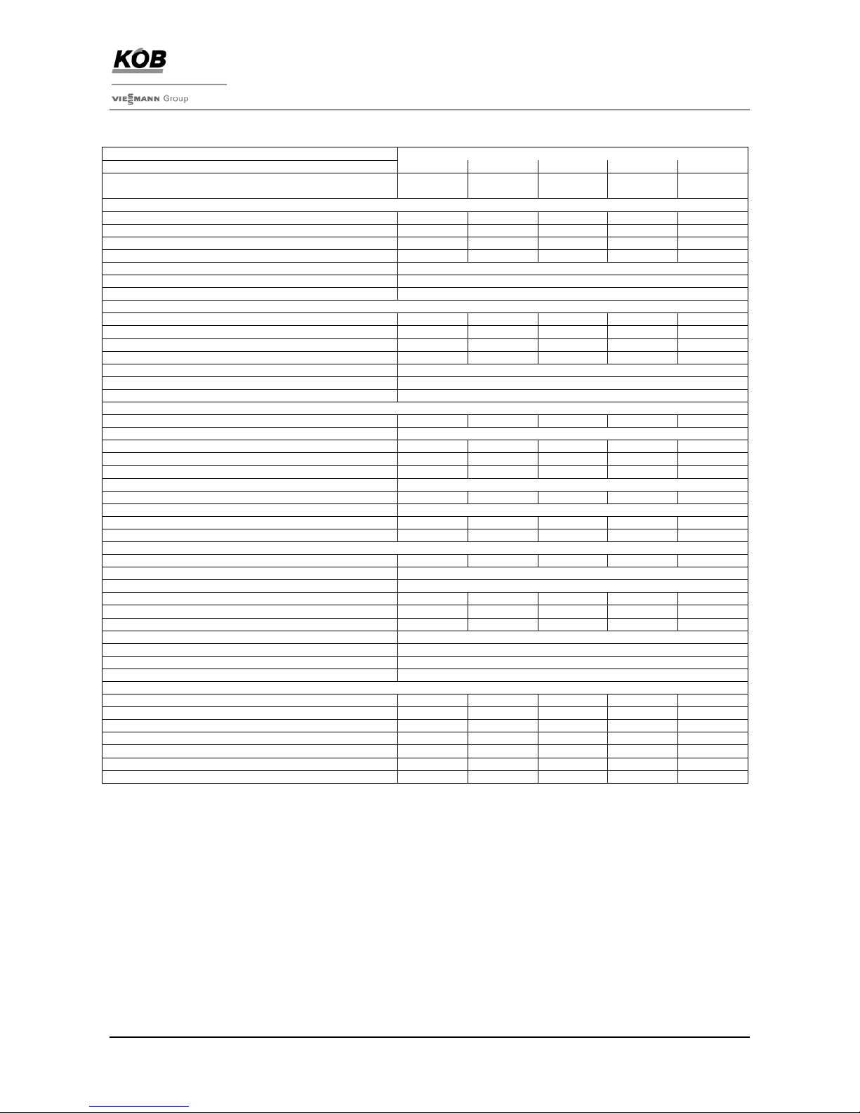
Technical data:
PYROTEC Grate Firing System
Trade name 390 530 720 950 1250
Art. No.:
KPT-390
7387607
KPT-530
7387414
KPT-720
7387605
KPT-950
7378080
KPT-1250
7387606
Performance data
Nominal heat output Q
N
[kW] 390 530 720 950 1250
Continuous output 1) QD [kW] 390 530 720 950 1250
Minimum heat output 2) Q
min
[kW] 97 132 180 238 312
Heat output chips W 45 Q
W45
[kW] 380 515 700 920 1210
Efficiency in operation to be performed
3)
[%] > 90
Maximum water content
4)
[%] W 50
Size of the chips
5)
G 30 / G 50 as per ÖNORM M7133
Exhaust gas figures
Mass flow rate QN; W5; O2 8%; [g/s] 219 297 404 532 700
Volume flow QN; W5; O2 8%; 150°C [m³/s] 0.26 0.36 0.48 0.63 0.83
Mass flow rate Q
W45;
W45; O2 10%; [g/s] 303 412 560 736 968
Volume flow Q
W45
; W45; O2 10%; 150°C [m³/s] 0.37 0.50 0.67 0.88 1.15
Average exhaust gas temperature at Q
N
6)
[°C] 160
Average exhaust gas temperature at Q
min
6)
[°C] 120
Chimney draught required [Pa] +-0
Electrical connections
Electrical connections, total [kW] 5.41 7.02 8.12 9.35 11.15
Ignition device [kW] 1.6
Exhaust blower [kW] 1.1 1.1 2.2 2.2 4.0
Feed auger [kW] 1.1 1.5 1.5 2.2 2.2
Primary air blower 1 [kW] 0.14 0.3 0.3 0.48 0.48
Primary air blower 2 [kW] 0.9
Secondary airflow fan [kW] 0.9 1.5 1.5 1.85 1.85
Grate drive unit [kW] 0.12
Electric power consumption at QN [kW] 2.88 3.57 4.56 5.17 6.79
Electric power consumption at Q
min
[kW] 2.34 2.9 3.71 4.15 5.47
Heating-relevant specs
Volume on heating gas side [ltr] 1540 2280 2830 4050 5210
Volume of ash container for grate ash [ltr] 240 / 800
Volume of ash container for exhaust gas de-duster [ltr] 240 / 800
Water-bearing resistance (Diff. 15 K) [mbar] 13 23 43 26 45
Boiler water volume [ltr] 1150 1444 1861 1943 2482
Heating surface [m²] 26.32 42.50 55.50 74.80 91.00
Test pressure [bar] 7.8
Maximum operating pressure [bar] 6
Maximum boiler temperature [°C] 100
Minimum return temperature [°C] 65
Weights
Weight of fire block [kg] 2970 4238 4953 5779 6520
Weight of boiler [kg] 1680 2707 3291 4874 5563
Weight of displacement rods [kg] 394 394 394 538 538
Weight of exhaust blower [kg] 60 62 78 82 107
Weight of feed auger [kg] 153 153 153 190 190
Total weight without water
7)
[kg] 5230 7554 8869 11463 12918
Total weight with water
7)
[kg] 6380 8998 10730 13406 15400
1)
Continuous output: Output levelling out as base load boiler in continuous operation with pneumatic
cleaning.System (for track time, see Operating Instructions)
2)
Q ≥ Q
min :
Operation with modulated control (Infinitely variable power control)
Q ≤ Q
min
: Low load with ON Q
min
/ ember maintenance operation
3)
Efficiency: For dry fuels (W5 to W20) without flue gas recirculation system reduced values
For PYROTEC 720 – 1250 without displacement rods reduced values
4)
Wet fuels: >W45 further restrictions in terms of output, efficiency and control behaviour
5)
Specification: See Spec Sheet 1010, Minimum Requirements for Wooden Fuels
6)
Exhaust gas temperature: A reduction is possible by installing the displacement rods (QN - 20°C; Q
min
– 10°C)
Other influences: Fuel, water content, ash content, pneumatic cleaning
system yes/no;track time (number of operating hours without cleaning)
Specifications for the start of the track time (toward the end of the track time there is
an increase in the exhaust gas temperature by approx. + 15°C)
7)
Total weight: incl. displacement rods
Page 3

Spec Sheet
PYROTEC Grate Firing System
Boiler Plant
Köb Holzheizsysteme GmbH, Flotzbachstr. 33, A-6922 Wolfurt, Tel. +43/5574/6770-0, Fax 65707, E-Mail: office@kob.cc
Subject to technical changes
7010-3
2009-03-01_GB
Dimensional drawing:
Boiler bearin g su rface
Floor with heat-resistant
design additional
Front
(boiler door)
The floor construction has to be free
of any pipes or installation lines!
Danger through the effects of heat!
1) 800 mm access, firing block
960 mm if there is a door stop & pneum. cleaning system
Position of approx. 110° required for manual cleaning of heat exchanger
FIRING BLOCK
BOILER
FEED AUGER
CONNECTION TO DE-DUSTER
see spec sheet 7110
530 / 720
connection at the centre
950 / 1250
choice of connection
left or right
Page 4

Spec Sheet
PYROTEC Grate Firing System
Boiler Plant
Köb Holzheizsysteme GmbH, Flotzbachstr. 33, A-6922 Wolfurt, Tel. +43/5574/6770-0, Fax 65707, E-Mail: office@kob.cc
Subject to technical changes
7010-4
2009-03-01_GB
Connections/dimensions:
PYROTEC [Art.-No.]
KPT-390
7387607
KPT-530
7387414
KPT-720
7387605
KPT-950
7378080
KPT-1250
7387606
Water connections PN 6 (see Spec Sheet 7960)
I Boiler forward flow DN 100 DN 100 DN 100 DN 125 DN 125
II Boiler return flow DN 100 DN 100 DN 100 DN 125 DN 125
III Connection for extinguishing water R ¾“ AG R ¾“ AG R ¾“ AG R ¾“ AG R ¾“ AG
IV Drain valve for boiler R 1 ½“ IG R 1 ½“ IG R 1 ½“ IG R 1 ½“ IG R 1 ½“ IG
V Safety heat exchanger 4 x R ½“ AG 4 x R ½“ AG 8 x R ½“ AG 8 x R ½“ AG 8 x R ½“ AG
VI Dipping shell for thermic safety outlet 1 x R ½“ IG 1 x R ½“ IG 2 x R ½“ IG 2 x R ½“ IG 2 x R ½“ IG
Connection exhaust gas pipe Ø [mm]
A 350 350 350 400 450
Location of the connections [mm]
a 2077 2331 2491 2444 2639
b 2060 2560 2562 2562 3107
Dimensions of the foundations [mm]
d 4221 4721 4912 5096 5641
e 1260 1260 1400 1630 1630
f 2561 3061 3112 3066 3611
g 1026 1026 1112 1360 1360
h 1826 1826 1912 2160 2160
Dimensions of the boiler [mm]
B 1274 1274 1380 1612 1612
C 1263 1417 1413 1371 1566
D 1350 1850 1800 1600 2100
E 4370 4870 5257 5447 5992
F 1086 1086 1380 1612 1612
G 2405 2905 2993 2861 3406
H 577 577 577 657 657
K 1200 1200 1200 1275 1275
L 2328 2486 2784 2981 3176
M 2378 2536 2834 3035 3230
N 308 308 308 440 440
O 803 803 803 929 929
P 453 453 453 479 479
R 3282 3782 3877 3835 4380
S 3800 4300 4434 4392 4937
Parts for maintenance
1 Fire box door with solid double hinging
2 Boiler door
3 Cleaning lid for burner trough
4 Cleaning lid for external grate
5 Cleaning lid for flue gas collector
6 Pneumatic cleaning system Article KPT-W…-S Spec Sheet 7120
Electric drives & ignition
10 Feed auger
11 Drive for grate drive
12 Ignition device
13 Primary air blower 1
14 Primary air blower 2
15 Secondary airflow fan
16 Exhaust blower Dimensions : / Spec Sheet 7110
17 De-ashing, fire box auger Article KPT-A.-S / Spec Sheet 7120
18 De-ashing system for ascending conveyor auger Article KPT-A.-S / Spec Sheet 7120
Switches and sensors These items are part of the Pyrocontrol control system
Article PYR-… / Spec Sheet 7800
20 Light barrier - feed auger
21 Limit switch for maintenance cover
22 Temperature sensor for feed auger
23 Light barrier for embers
24 Fire box temperature sensor (insertion side)
25 Negative pressure sensor (opposite insertion side)
26 Overpressure monitor for fire box
27 Light barrier for de-ashing
28 Limit switch fire box door
29 Burner sensor
30 Return circuit sensor
31 Temperature-limiting safety switch (STB)
32 Exhaust gas sensor Location: Spec Sheet 7110
33 Lambda sensor with measuring transducer Location: Spec Sheet 7110
 Loading...