

Page 1
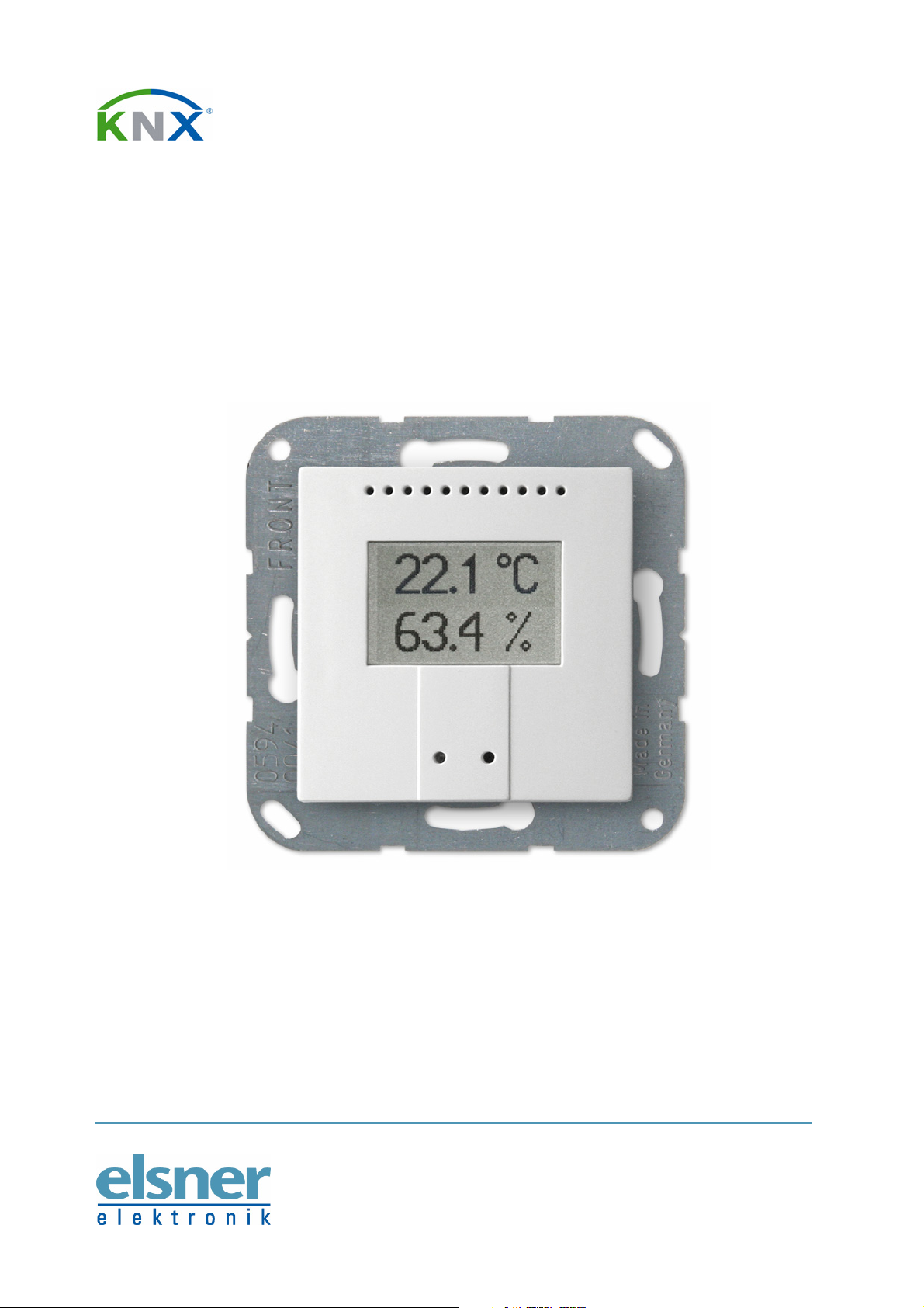
Thermo-Hygrometer
KNX TH-UP
Technical Data
and Installation Notes
Elsner Elektronik GmbH Steuerungs- und Automatisierungstechnik
Herdweg 7 • D-75391 Gechingen • Germany
Phone: +49 (0) 70 56/93 97-0 • Fax: +49 (0) 70 56/93 97-20
info@elsner-elektronik.de • www.elsner-elektronik.de
Page 2

Description
The Indoor Sensor KNX TH-UP measures temperature and humidity and calculates the
dew point. The sensor can receive external measured values via the bus and process
them with the own data to an overall temperature and overall air humidity (mixed
values).
The KNX TH-UP provides seven switching outputs with adjustable threshold values as
well as additional AND and OR logic gates. The sensor has got a PI controller for
heating and cooling (depending on temperature) and for ventilation (depending on air
humidity) and it can emit a warning to the bus as soon as the area of optimum comfort
(according to DIN 1946) is left.
The integrated display shows the own values and data received from the bus (e. g. date,
time). The housing is completed with a frame of the switching series installed in the
building and thus merges with the interior.
Functions:
• Measurement of temperature and air humidity (relative, absolute), calculation
of dew point
• Display 1-3 rows (own values or values received from the bus)
• Mixed values from own measured values and external values (proportions can
be set in percentage)
• PI controller for heating (one or two step) and cooling (one or two step)
depending on temperature
• PI controller for ventilation depending on humidity: Dehumidify/humidify (one
step) or dehumidify (one or two step)
• 7 switching outputs with adjustable threshold values (Threshold values can be
set by parameter or via communication objects)
• 4 AND and 4 OR logic gates with each 4 inputs. Every switching incident as
well as 8 logic inputs (in the form of communication objects) may be used as
inputs for the logic gates. The output of each gate may optionally be configured as
1 bit or 2 x 8 bits
Configuration is made using the KNX software ETS. The programme file (format VD2)
and the manual can be downloaded from the Elsner Elektronik homepage on
www.elsner-elektronik.de in the “Service” menu.
Scope of delivery
• Housing with display and sensor board
• Base plate
You will need in addition (not supplied):
• Socket ∅ 60 mm, 42 mm deep
• Frame (for element 55 x 55 mm), suitable for the switching programme used in the
building
2
KNX TH-UP Indoor Sensor • Date of issue: 13/01/2010 • Technical changes reserved. Errors reserved.
Page 3

Technical specifications
Housing: Plastic material (partly lacquered)
Colours: • White glossy (similar to RAL 9016 Traffic White)
• Aluminium matt
• Anthracite matt
• Stainless steel
• Special colours on request
Mounting:
In-wall (in socket ∅ 60 mm, 42 mm deep)
Protection category: IP 20
Dimensions:
Housing approx. 55 × 55 (W × H, mm), mounting depth
approx. 15 mm, base plate approx. 71 × 71 (W × H, mm)
Total weight: approx. 50 g
Ambient temperature: Operation -10…+50°C, storage -20…+60°C
Ambient air humidity: max. 95% R. H., avoid bedewing
Operating voltage: KNX bus voltage
Bus current: max. 6 mA,
max. 10 mA when programming LED is active
Data output: KNX +/- bus terminal plug
BCU type: Own micro controller
PEI type: 0
Group addresses: max. 184
Allocations: max. 184
Communication objects: 117
Measurement range
-40…+100°C
temperature:
Resolution: 0.1°C
Accuracy: ± 0.4°C at 25°C
Measurement range
0…100%
humidity:
Resolution: 0.1%
Accuracy:
0…20 % = ± 5% R. H.
20…80 % = ± 3% R. H.
80…100 % = ± 5% R. H.
Drift: ± 0.5% R. H. per year in normal air
The following standards have been considered for the evaluation of the product in
terms of electro magnetic compatibility:
KNX TH-UP Indoor Sensor • Date of issue: 13/01/2010 • Technical changes reserved. Errors reserved.
3
Page 4

Transient emissions:
• EN 60730-1:2000 Section EMV (23, 26, H23, H26) (threshold category: B)
• EN 50090-2-2:1996-11 + A1:2002-01 (threshold category: B)
• EN 61000-6-3:2001 (threshold category: B)
Interference resistance:
• EN 60730-1:2000 Section EMV (23, 26, H23, H26)
• EN 50090-2-2:1996-11 + A1:2002-01
• EN 61000-6-1:2004
The product has been tested for the above mentioned standards by an accredited EMV
laboratory.
Installation and Commissioning
Installation, inspection, commissioning and troubleshooting
of the sensor must only be carried out by a competent
electrician.
Disconnect all lines to be assembled, and take safety precautions against accidental
switch-on.
The sensor is exclusively intended for appropriate use. With each inappropriate change
or non-observance of the instructions for use, any warranty or guarantee claim will be
void.
After unpacking the device, check immediately for any mechanical damages. In case of
transport damage, this must immediately notified to the supplier.
If damaged, the sensor must not be put into
operation.
If an operation without risk may supposedly not be guaranteed, the device must be put
out of operation and be secured against accidental operation.
The sensor must only be operated as stationary system, i.e. only in a fitted state and
after completion of all installation and start-up works, and only in the environment
intended for this purpose.
Elsner Elektronik does not assume any liability for changes in standards after
publication of this instruction manual.
4
KNX TH-UP Indoor Sensor • Date of issue: 13/01/2010 • Technical changes reserved. Errors reserved.
Page 5

Installation position
The KNX TH-UP will be installed concealed within a socket (∅ 60 mm, 42 mm deep) and
fitted with a frame from the switching programme used in the building.
In selecting an installation location, please take care that no direct sunlight, heating
element or draught from windows or doors will distort the values measured. Infiltration
from pipes that lead to the socket where the sensor is installed from other rooms may
cause false measurement results, too.
The sensor may be installed and operated in dry interior
rooms only. Avoid condensation.
Composition
Casing
1 Notches
2 Air circulation holes
3 Programming LED (recessed)
4 Programming button (recessed) for teaching instrument
5 Air circulation holes (BOTTOM)
KNX TH-UP Indoor Sensor • Date of issue: 13/01/2010 • Technical changes reserved. Errors reserved.
5
Page 6

Rear view of casing with sensor board
1 Notches
2 Slot for KNX terminal BUS +/-
Assembly
First of all fit the socket with connection. Seal inlet pipes to avoid infiltration. Then
screw the base plate onto the socket and position the frame of the switching
programme.
Connect the bus line +/- (black-red plug) to the terminals provided on the sensor board
of KNX TH-UP. Pin the sensor with the notches on to the metal frame, so that sensor
and frame are fixed.
Notes on installation
Sensor must not be exposed to water (rain) or dust. This could result in the electronic
being damaged. A relative air humidity of 95% must not be exceeded. Avoid bedewing.
6
KNX TH-UP Indoor Sensor • Date of issue: 13/01/2010 • Technical changes reserved. Errors reserved.
 Loading...