

Page 1

Technical Manual
KRISTAL Line
KNX Capacitive Keypads
Page 2

CONTENTS'
'
'
1 General'Information'
'
2 Product'Features'
'
3 ETS'Library'
'
3.1 General'Parameters'
3.2 Input1,'Input2,'Input3,'Input'4'
3.2.1 Switching'Mode'
3.2.2 Button'Mode'
3.2.3 Dimmer'Mode'
3.2.4 Scene'Mode'
3.2.5 Blind'-'Shutter'Mode'
'
'
Page 3

1 General'Information'
'
!"#$%&'(#$(&()*+,'-%-('#.-(*/()&,&)#%#0-(1-2,&3$(3-$#4.-3(%*()*.%"*'(!56(3-0#)-$7(
89-( 1-2,&3$( &"-( &0&#'&:'-( #.( %9-( /*"+&%( ;<++( =( ;<++( /*"( #.$%&''&%#*.( #.( "*>.3( )*..-)%*"(
:'*)1$( ?@6AB=C( *"(#.(%9-(/*"+&%(DE<++(=(;<++(/*"(#.$%&''&%#*.(#.(F%&'#&.()*..-)%*"(:'*)1$(
G*3-'(H<I(?@6AJ=C7(
@*%9(+*3-'$(&"-(&0&#'&:'-(#.(%9-(K9#%-(?KC(&.3(@'&)1(?@C()*'*>"(*,%#*.$7(
(
L-"-(:-'*M(&"-(%9-(,"*3>)%$N(#3-.%#/#)&%#*.()*3-$O(
(
@6AP<E@ EA)*.%"*'(+*3-'(;<=;<Q(@'&)1(
@6AP<EK EA)*.%"*'(+*3-'(;<=;<Q(K9#%-(
@6AP<R@ RA)*.%"*'(+*3-'(;<=;<Q(@'&)1(
@6AP<RK RA)*.%"*'(+*3-'(;<=;<Q(K9#%-(
@6AP<S@ SA)*.%"*'(+*3-'(;<=;<Q(@'&)1(
@6AP<SK SA)*.%"*'(+*3-'(;<=;<Q(K9#%-(
(
@6AJ<I@ IA)*.%"*'(+*3-'(DE<=;<Q(@'&)1(
@6AJ<IK IA)*.%"*'(+*3-'(DE<=;<Q(K9#%-(
@6AJ<S@ SA)*.%"*'(+*3-'(DE<=;<Q(@'&)1(
@6AJ<SK SA)*.%"*'(+*3-'(DE<=;<Q(K9#%-(
@6AJ<;@ ;A)*.%"*'(+*3-'(DE<=;<Q(@'&)1(
@6AJ<;K ;A)*.%"*'(+*3-'(DE<=;<Q(K9#%-(
(
T&)9( 3-0#)-( ,"*0#3-$( )*.%"*'( />.)%#*.$( %*( ,*M-"( *.( >$-"$Q( *,-.( &.3( )'*$-( $9>%%-"$Q( &3U>$%(
$*>")-$(*/('#49%#.4(&.3($-'-)%($)-.-$7(
V*+-(*/(%9-$-(/-&%>"-$('-0-"&4-(%9-(,*$$#:#'#%2(*/("-)*4.#$#.4(&(,"*'*.4-3()*.%&)%(%*(,-"/*"+(
&>=#'#&"2(&)%#*.$7(
89#$(,"*3>)%()&.(:-(>$-3(/*"(:*%9(9*+-(&.3(#.3>$%"#&'(&,,'#)&%#*.$7(
(
89-(,"*3>)%$(3-$)"#:-3(#.(%9#$(+&.>&'(&''(>$-(%9-(T8V('#:"&"2(.&+-3(
BX-QxRx_AV01.vd5'
(
Page 4

2 Product'Features'
'
89-(:>%%*.$(#.%-"/&)-(#$(,*M-"-3(0#&(%9-(!*..-=(:>$(&.3(3*-$(.*%(.--3(&.2(&33#%#*.&'(,*M-"(
$>,,'#-$7(
89-(1-2,&3$(9&0-(@WXT(:&)1'#49%#.4(:-9#.3( -&)9( )*.%"*'( &.3(KLF8T( :&)1'#49%#.4( &''( &'*.4(
%9-#"(%"&.$,&"-.%(-34-$(%*(#''>+#.&%-(%9-(M&''7(
@*%9(&"-()*.%"*''&:'-(M#%9($>#%&:'-(T8V()*++>.#)&%#*.(*:U-)%$7((
89-(3-0#)-( #$( -B>#,,-3(M#%9( &(:>YY-"Q( &'$*(,"*4"&++&:'-( 0#&(T8VQ( #.( *"3-"( %*( *//-"(%9-( :-$%(
&)*>$%#)(/--3:&)17(
89-(#.%-"/&)-( #$( &'$*(-B>#,,-3( M#%9( &(,"*=#+#%2( $-.$*"( %*( %>".( *.( &$( %9-( >$-"N$( 9&.3( +*0-$(
)'*$-"7(
89-( FZE<( )&$#.4( #$( 3-$#4.-3( /*"( #.$%&''&%#*.( #.$#3-( )*..-)%*"( :'*)1$( #.%-.3-3( %*( &))-,%(
)*.0-.%#*.&'(,>$9A:>%%*.$7(
[#=#.4( #$( 3*.-( M#%9( &( $,"#.4A%2,-( '&%)9( %*( &( /"&+-( M9#)9( +>$%( :-( ,"-0#*>$'2( /#=-3( %*( %9-(
)*..-)%*"(:'*)1(0#&(%9-(&,,"*,"#&%-($-'/A%&,,#.4($)"-M$7(
(
(
(
Page 5
(
3 ETS'Library'
'
89-(T8V(W#:"&"2(/-&%>"-$(&(.>+:-"(*/(,&"&+-%-"$(>$-3(%*()9&"&)%-"#$-(%9-( *,-"&%#*.( */(-&)9(
)*.%"*'(*/(*>"(1-2,&37(
89-(,&"&+-%-"$(&"-()*.0-.#-.%'2(3#0#3-3(#.%*(,&4-$(/*"(%9-()*./#4>"&%#*.(*/(-&)9()*.%"*'Q(M#%9(
&.(&33-3(+&#.(,&4-(/*"(%9-($-'-)%#*.(*/(M9#)9(3-0#)-(%2,-($9*>'3(:-(#.$%&''-37(
(
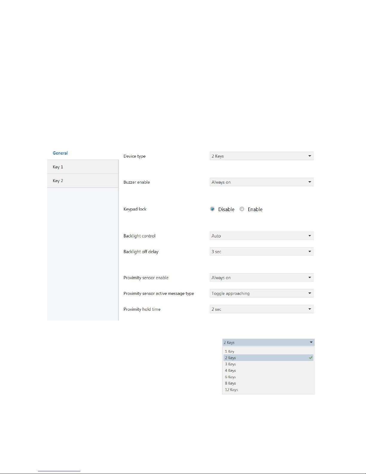
3.1 General Parameters
Below is the General parameters page reached by activating the ETS control Edit
Parameters.
This ETS library is applicable to a number of products which differ in shape, colour
and above all, number of controls.
Therefore, it is first of all necessary to correctly
select the number of available keys on the device
that you are installing, so that the Library can
display all the parameters and communication
objects necessary for correct programming
accordingly.
Page 6

Parameters are listed here below that may affect the general operation of the
device.
The first relates to the enabling of the Buzzer to ensure
an acoustic feedback response when a control is
activated.
The buzzer can be turned off by enabling the Always off
function.
The buzzer can be turned permanently on by enabling the Always on function.
Alternatively, the Buzzer operation can be enabled or disabled through a
communication object (On with message 1 and On with message 0).
The second relates to the enabling of the
Keypad Lock to lock the keypad operation,
for example while the glass top is cleaned.
To enable the Keypad Lock means to display a Lock set communication object to be
able to receive a lock control.
In our case, ETS also displays an object for Lock status reading.
The third relates to the programming of the
Backlight.
The Backlight can be left always off (OFF) or
always on (ON), or it may be controlled by
communication objects (On with message 1 and On
with message 0).
Alternatively, operation can be automatic as a
function of proximity sensing, so as to be activated when sensing a hand.
In this case, a time delay can be set after which the Backlight will go off.
Page 7

3.2 Key1, Key 2, Key3, …Key12
Below is the image typically opening the key configuration dedicated page.
The first parameter, Mode, is the most
important one and determines the mode of
operation of the corresponding key.
There are 6 different modes of operation that
will be described below - including the
possibility of disabling the control.
The remaining parameters are determined dynamically according to the type of
function chosen and will change from time to time.
The last parameter is, however, shared by all the modes of operation and can be
described in general terms in this introduction.
It is the Key brightness, a feature that allows
the control light feedback to be controlled.
By selecting the Always off option, the
feedback can stay off all the time, while by
selecting Always on it can stay always
switched on.
Alternatively, you can decide that it should
change state when touched, going on if it was off (Normally Off, On when touched)
or off if it was previously on (Normally On, Off when touched).
Finally, it can be programmed to be controlled via a communication object (On with
message 1 and On with message 0).
Page 8

3.2.1 Switch Mode
The Switch mode enables to send a KNX telegram to coincide with one of the
possible events linked with the contact between finger and keypad.
By defining a Contact type of the normally open type, the telegram will be
transmitted upon keypad/finger contact start.
By defining a Contact type of the normally closed type, the telegram will be
transmitted upon finger/keypad contact end, or when the user's finger moves away.
The definition of the Contact type property determines the event upon which the
telegram will be transmitted on the KNX bus.
Every time that the keypad is touched, a telegram is sent the value of which can be
specified via the Short press function parameter.
This value can be always the same or always change for each event.
By selecting ON you will be able to always send the ON value (1) at each event.
By selecting OFF you will be able to always send the OFF value (0) at each event.
By selecting ON/OFF you will be able to change the value sent upon each event, by
alternating each time the values ON and OFF (Toggle Mode).
Finally, it is possible to activate the Long press function mode.
This allows two events to be managed with each input:
the short press event to activate a certain KNX control, or the long press event to
activate another KNX control.
This feature allows the number of controls manageable with a button interface to be
doubled.
Page 9

Enabling this feature activates the configuration of two new parameters.
The former, identified as Long press function, enables the definition of the value to
be transmitted - similarly to the procedure already described for the short function.
The latter allows the press time required to trigger a long press event to be
indicated.
In the event that Contact type is normally closed, the operation logic that we have
just described is completely reversed.
The Switching mode exposes an extremely simple 1 bit communication object to
transmit controls to the other KNX devices.
Page 10

This object is created to notify a State change that occurs in the field to coincide
with the already mentioned contacts.
Therefore, no other object will be found to notify the change of state!
This single communication object is also highly useful to synchronise the input
state with events notified on the KNX bus.
Warning!
The performance of the button interface changes when the Long press function is
enabled.
If the long press control is not expected, the KNX telegram is sent immediately, as soon
the pressure applied on the button is felt (rising edge).
Conversely, if the Long press function is activated, the interface must be left waiting to
know if the control will be long or short, by introducing a short latency time.
This latency can induce a feeling of failed control reactivity.
The user must be informed that this is a normal consequence of the need to wait for the
release of the button (trailing edge) - in order to assess whether the control to run will be
of the long or short type.
Page 11

3.2.2 Button Mode
This mode is suitable for active control - to control the closing of the relay while the
button is held down.
The device constantly reads the state of the input and sends a telegram whenever it
detects a change.
This means that a telegram is sent whenever there is a change in the status of our
inputs.
In the event that a button is used, a telegram is sent at the time of pressure
application and then a telegram is also sent at the time of release.
Like in the previous case, Contact type is the property that determines with which
event the notification of telegrams on the KNX bus is synchronised.
If Contact type is defined as normally open (standard) the datum is sent on the
rising edge, therefore it is worth 1 when the contact closes and 0 when the contact
opens.
If Contact type is defined as normally closed, the telegram 1 is sent at the end of the
Closed contacts event and the logic is reversed.
Therefore, you will read 1 when the contacts are open and you will read 0 when the
contacts are closed.
The Button mode, too, exposes a single plain communication object that operates in
the manner already described for the Switching function.
Page 12

3.2.3 Dimmer Mode
This is the function suitable for adjusting the brightness of a dimmable light.
The Dimmer function is one of the modes that automatically enables the use of a
Long press function to have a second control available.
The Short control is used to switch the light on and off and enables a 1bit
communication object named Switching; it will function exactly like the previously
described switching function.
The Long control is used to adjust the light intensity and enables a 4 bit
communication object named Dimming.
This means that, in order to turn on and turn off the light, a short press only will be
required, while in order to adjust the brightness, the control should be held down
until the required brightness is obtained.
After the time interval required to activate the Long control, a telegram will be sent
with the dimming START control.
Page 13

After obtaining the desired brightness we will be able to release the button by
automatically causing the sending of the dimming STOP control.
Like in all previous cases, the Contact type property defined as Normally closed
will determine the reversal of the operation logic.
The effectiveness of the adjustment depends above all on the speed with which the
dimmer changes the brightness and is a parameter generally settable from the
actuator.
The Long control can operate in 3 different modes.
It can act in the Brighter mode to increase the
brightness, or in the Darker mode to decrease the
brightness, or it can toggle from time to time
between these two modes to be able to fully control
the Dimmer with a single control.
Finally, we are describing here below the Dimmer
Step parameter.
This parameter determines by how much we can
increase or decrease the brightness with a single
Long press action.
100% means to be able to increase or decrease the
brightness throughout the required width.
50% means to be able to increase or decrease the
brightness up to half the required width. This means that in order to cover all of the
available range, we will have to perform two actions.
The possible variation with a single action can decrease up to 1%.
Page 14

3.2.4 Scene Mode
This is the function that allows control over the KNX Scenes.
Controlling a KNX scene means to be able to retrieve it when needed or be able to
store a new configuration.
Each scene is defined by an identification number (ID) which can vary between 1
and 64.
To activate a scene consists in sending a byte to the KNX bus with value (ID - 1).
This control is assigned to the Short function.
Therefore every time that a short press is applied the configured scene will be
recalled.
To store a new scene consists in sending a byte to the KNX bus with value (ID + 64).
Sending the memory storage control is assigned to the Long function.
Therefore, every time that a long press is applied a new scene programming will be
controlled.
This feature can be enabled or disabled via the Enable long press function
property.
Page 15

3.2.5 Blind - Shutter Mode
This is the function that allows control over the shutters and blinds actuators.
The main feature of a shutter/blind control is the fact that it is actuated via two
different group addresses: the first to control the shutter movement, and the
second to control the shutter stop and the venetian blind movement.
Therefore, the interface must necessarily display two distinct communication
objects for movement and stopping.
The STOP control is assigned to the Short function.
The MOVE control is assigned to the Long function.
This means that every time a short press is applied, the roller shutter movement is
stopped and every time a long press is applied, the roller shutter is set in motion.
This setting allows for the shutter to be set in motion and let run to the end of its
stroke without any need to hold the button down.
Should you wish to stop it earlier, a short press can be applied to send a STOP
control.
Page 16

The movement control can be programmed
both to raise the roller shutter (UP = 0) and
to lower it (DOWN = 1).
When a given movement is assigned to an
input, it should be borne in mind that two inputs are required to ensure full
actuator control: one to raise and the other to lower the roller shutter.
An UP/DOWN mode is also available to save interface resources and be able to
always toggle the control sent.
In this way, a single channel can be used for both functions.
The value assigned to STOP in order to stop the shutter movement is generally not
influential.
Whatever value is assigned, it always results in the roller shutter stopping.
A different case is that of a shutter already at a stop.
In that case, sending a STOP control is interpreted as a control to actuate the slats in order to adjust the brightness through the venetian blind.
In this case, the value assigned to STOP determines the direction of rotation of the
slats, increasing or decreasing the venetian blind light-blocking ability.
Our interface always sends a slat control in an opposite direction of rotation to the
last movement performed, to reflect the different position of the slats after the upstroke or down-stroke of the venetian blind.
The down-stroke (DOWN = 1) of the venetian blind is always preceded by a release
of the slats to a fully light-blocking position, therefore the subsequent adjustment of
the slats must be in the opposite direction to increase the brightness (STOP = 0).
Conversely, the up-stroke (UP = 0) of the venetian blind is always preceded by a
recall of the slats to a horizontal position, with minimal light-blocking effect,
therefore the subsequent adjustment of the slats must be in the opposite direction
to increase the shading effect (STOP = 1).
 Loading...