

Knox Video RS16x16HB User Manual

RS16x16HB
Operation and Technical Manual
Limited Warranty
Unless otherwise stated in the product specific documentation received
with this product, Knox Video Technologies provides a five-year limited
warranty for this product. The above warranty period shall begin on the
date of shipment by Knox to purchaser or, if purchaser is an authorized
reseller of such Knox products, from the date of shipment by the reseller to
the reseller’s original customer .
The warranty set forth above shall not apply to failure or deficiency
which has been caused by misuse, abnormal or unusually heavy use, neglect,
alteration, improper installation, unauthorized repair or modification, improper
testing, accidental or causes external to the product such as but not limited
to excessive heat or humidity , power failure, or improper installation.
IF SER VICE IS REQUIRED:
If the product does not perform as warranted, call Knox V ideo T echnologies
at 301-840-5805 for available service options.
If it is necessary to return an item to Knox, the defective product should be
securely packaged in original boxes and insured for shipment. Owner agrees
to insure and accept all liability for loss of or damage to this product.
KNOX VIDEO
TECHNOLOGIES
8547 Grovemont Circle
Gaithersburg, MD 20877
TEL 301•840•5805
FAX 301•840•2946
www.knoxvideo.com
YOU MUST CALL TECHNICAL SUPPORT AT 301-840-5805 FOR
A RETURN AUTHORIZATION NUMBER (RA) AND “SHIP-TO”
ADDRESS BEFORE SHIPPING ANY PRODUCT TO KNOX.
This warranty gives you specific legal rights, and you may also have other
rights, which vary from state to state.
Knox Video Technologies
8547 Grovemont Circle
Gaithersburg, MD 20877
301-840-5805 / 301-840-2946 Fax
www.knoxvideo.com
Warnings, Cautions and Others
Mises en garde, precautions et indications diverses
CAUTION
RISK OF ELECTRIC SHOCK
DO NOT OPEN
CAUTION: TO REDUCE THE RISK OF ELECTRIC SHOCK,
DO NOT REMOVE COVER (OR BACK)
NO USER SER VICEABLE PAR TS INSIDE
REFER SER VICING TO QUALIFIED SERVICE PERSONNEL
For U.S.A.
This equipment has been tested and found to comply with the limits for a Class B digital
device, pursuant to part 15 of the FCC Rules. These limits are designed to provide reasonable
protection against harmful interference in a residential installation.
This equipment generates, uses and can radiate radio frequency energy and, if not installed and
used in accordance with the instructions, may cause harmful interference to radio
communications. However, there is no guarantee that interference will not occur in a particular
installation. If this equipment does cause harmful interference to radio or television reception,
which can be determined by turning the equipment off and on, the user is encouraged to try to
correct the interference by one or more of the following measures:
Reorient or relocate the receiving antenna.
Increase the separation between the equipment and receiver.
Connect the equipment into an outlet on a circuit different from that to which the receiver is
connected.
Consult the dealer or an experienced radio/TV technician for help.
The lightning flash with arrowhead symbol, within an
equilateral triangle, is intended to alert the user to the
presence of uninsulated “dangerous voltage” within the
product’s enclosure that may be of sufficient magnitude
to constitute a risk of electric shock to persons.
The exclamation point, within an equilateral triangle, is
intended to alert the user to the presence of important
operating and maintenance (servicing) instructions in the
literature accompanying the appliance.
WARNING: TO REDUCE THE RISK OF FIRE OR ELECTRIC SHOCK, DO
NOT EXPOSE THIS APPLIANCE TO RAIN OR MOISTURE.
CAUTION
To reduce the risk of electrical shocks, fire, etc.:
1. Do not remove screws, covers or cabinet.
2. Do not expose this appliance to rain or moisture.
A TTENTION
Afin d’éviter tout risque d’électrocution, d’incendie, etc.:
1. Ne pas enlever es vis ni es panneaux et ne pas ouvrir le coff ret de
l’appareil.
2. Ne pas exposer l’appareil a la pluie ni a l’humidité.
Caution — STANDBY/ON switch!
Disconnect the mains plug to shut the power off completely. The STANDBY/ON
switch in any position does not disconnect the mains line. The power cannot be
remote controlled.
Attention — Commutateur STANDBY/ON!
Déconnecter la fiche de secteur pour couper complètement le courant. Le
commutateur ST ANDBY/ON ne coupe jamais complètement la ligne de secteur,
quelle que soit sa position. Le courant ne peut être télécommandé.
For Canada/pour le Canada
CAUTION: TO PREVENT ELECTRIC SHOCK, MATCH WIDE BLADE OF PLUG TO
WIDE SLOT, FULLY INSERT.
ATTENTION: POUR EVITER LES CHOCS ELECTRIQUES, INTRODUIRE LA LAME LA
PLUS LARGE DE LA FICHE DANS LA BORNE CORRESPONDANTE DE LA PRISE ET
POUSSER JUSQUAU FOND.
For Canada/pour le Canada
THIS DIGITAL APPARATUS DOES NOT EXCEED THE CLASS B LIMITS FOR RADIO
NOISE EMISSIONS FROM DIGITAL APPARATUS AS SET OUT IN THE INTERFERENCECAUSING EQUIPMENT STANDARD ENTITLED “DIGITAL APPARATUS,” ICES-003
OF THE DEPARTMENT OF COMMUNICATIONS.
CETAPPAREIL NUMERIQUE RESPECTE LES LIMITES DE BRUITS RADIOELECTRIQUES APPLICABLES AUX APPAREILS NUMERIQUES DE CLASSE B PRESCRITES
DANS LA NORME SUR LE MATERIEL BROUILLEUR: “APPAREILS NUMERIQUES,”
NMB-003 EDICTEE PAR LE MINISTRE DES COMMUNICATIONS.
CAUTION:
• Do not block the ventilation openings or holes.
(If the ventilation openings or holes are blocked by a newspaper or cloth, etc., the heat may not be
able to get out.)
• Do not place any naked flame sources, such as lighted candles, on the apparatus.
• When discarding batteries, environmental problems must be considered and local rules or laws
governing the disposal of these batteries must be followed strictly.
• Do not use this apparatus in a bathroom or places with water. Also do not place any containers filled
with water or liquids (such as cosmetics or medicines, flower vases, potted plants, cups, etc.) on top
of this apparatus.
ATTENTION:
• Ne bloquez pas es orifices ou es trous de ventilation.
(Si es orifices ou es trous de ventilation sont bloqués par un journal un tissu, etc., la chaleur peut ne
pas être évacuée correctement de l’appareil)
• Ne placez aucune source de flamme nue, telle qu’une bougie, sur l’appareil.
• Lors de la mise au rebut des piles, veuillez prendre en considération es problèmes de l’environnement
et suivre strictement les règles et les lois locales sur la mise au rebut des piles.
• N’utilisez pas cet appareil dans une salle de bain ou un autre endroit avec de l’eau.
• Ne placez aucune récipient contenant de l’ear (tel que des cosmétiques ou des médicaments, un vase de
fleurs, un pot de fleurs, une tasse, uec.) sur cet appareil.

KNOX VIDEO
RS16x16HB ROUTING SWITCHER
KNOX VIDEO
RS16x16HB ROUTING SWITCHER
SECTION 1. GENERAL INFORMATION
1.1 INTRODUCTION
The RS16x16HB routing switcher is a device which accepts up to sixteen video
inputs and up to sixteen stereo audio inputs (that is, sixteen channels of left and right
audio), and connects any one of the input channels (buffered electrically) to one or
more of the sixteen outputs.
1.2 TECHNICAL DESCRIPTION
The RS16x16HB uses a single chip microprocessor with backup battery to
drive three monolithic latching crosspoint decoders, one for video and one for
each channel of audio. The video channel features a driver stage with a gain of two
to drive a 75 ohm coaxial line. The audio is set up for high impedance balanced
inputs and outputs with a gain of one, or optional 600 Ohm balanced inputs and
outputs at up to +l6db.
Crosspoint information is collected by the microprocessor from either the front
panel keypad or from the RS232 port on the rear panel, and distributed to the
crosspoint decoders. Audio and video may be routed together or separately. The
microprocessor program activates an automatic lamp test at powerup or when the
lamp test is called by front panel keypad or RS232 port. Each time a routing command
is sent, the entire current routing map can be reported on the RS232 port.
1.3 DET AIL SPECIFICA TIONS
Video Channels
Levels: 1 v. composite picture video or black burst: with a variety of
line resolutions including 525,625,825,875, and 1025, with a
variety of television systems including NTSC, P AL, SECAM,
and others
Frequency Response: DC to 200MHz
@ 300mv, <-3dB @ 150MHz
@ 1.0v,<-3dB @ 1 15MHz
Input Impedance: 75 oh m
Output Impedance: 75 o hm
Crosstalk:
all hostile:
T yp <-70dB @ 5MHz
T yp <-55dB @ 20MHz
T yp<-25dB @ 100MHz
one hostile:
<-40dB @ 200 MHz
Audio Channels, Unbalanced
Levels: 2 v. unbalanced audio, including
voice, music, PCM, control rack, SMPTE
time code, and others
Frequency Response: 20H z to 30KHz
Input Impedance: l00 Kohm
Output Impedance: 1 Kohm
Crosstalk: less than -85db @ 1KHz
Audio Channels, Balanced
Hum and noise: <-90db
Frequency response: 20Hz to 50K Hz +A ¼db
Level: 0, 4, or 16db, clipping at 18db
Impedance: Bridging, or 600 ohm termination
Crosstalk: <-90db ©20KHz
General
Connectors-Video: (32) BNC or RCA (as specified)
Connectors-Audio: (64) RCA (unbalanced)
Phoenix screwtype, removable (balanced)
Power Consumption: nominal 15vdc, 1.5A (from plug-
in module supplied)
Power Connector: 5mm/2mm coaxial
Dimensions: 6U rack
19” wide x 10.5” high x 2” deep
Shipping W eight: 8 pounds
Page 1 Page 2
KNOX VIDEO
RS16x16HB ROUTING SWITCHER
KNOX VIDEO
RS16x16HB ROUTING SWITCHER
SECTION 2. INST ALLA TION
WARNING!
Static Sensitive Connectors! During the installation process and whenever
changing cables to the Knox RS16x16HB inputs and outputs, use extreme caution
to avoid conducting static electricity to any inputs or outputs including video,
audio, and RS232.
DC Offset Warning! Connect standard video and audio inputs and outputs only .
Do not connect input or output signals with a positive or negative dc offset.
Chassis Ground is Earth Ground Do not connect video or audio cables with
induced or direct-connection potential on the shield.
2.1 INTRODUCTION
This section provides the information required for installation of the RS16x16HB
into its operating environment.
2.2 UNP ACKING AND INSPECTION
Unpack the RS16x16HB carefully and verify that the serial number matches the
number quoted on the packing list. Before installing it into a system, check the
outside of the unit carefully for signs of damage and check that none of the fasteners
have come loose.
Check that the power module is also present and marked for use with the
RS16x16HB product.
Units are shipped with a memory backup battery which retains the routing
crosspoint information when power is off. The battery is mounted on the printed
circuit board and is accessible from the rear panel. In the event that crosspoint
information is not retained during power off, the battery must be replaced. It is
recommended that the battery be replaced after five years. See Section 4,
Maintenance, for details on how to change the battery.
Choose a space in the rack which is convenient for all the cables and mount the
unit using standard rack bolts. Connect the output of the RS16x16HB power unit to
the power connector at the right rear (as viewed from the back of the panel) of the
RS16x16HB and plug the power unit into a grounded AC power outlet of the voltage
and frequency specified on the power unit. There is no power switch on the
RS16x16HB; it is designed to be ON at all times. (If it is desirable to have the
RS16x16HB powered down regularly, connect the power module to a switchable
AC power strip.)
2.4 VIDEO CONNECTIONS
Connect up to sixteen video sources (cameras, videocassette players, RF
demodulators, still-stores, character/graphics generators, etc.) to the input BNC
connectors marked VIDEO INPUT (or RCA connectors, if they were specified).
Inputs are automatically terminated in 75 ohms. T erminate unused outputs in
75 ohms.
Connect up to sixteen destination devices (monitors, VCRs, LCD projectors,
displays, RF modulators, etc.) to the sixteen BNC (or RCA) connectors marked
VIDEO OUTPUT . Be sure that all destination devices are terminated at 75 ohms.
Do not connect a SOURCE of video to any of the video OUTPUT connectors.
2.5 AUDIO CONNECTIONS
Connect up to sixteen audio sources (line level mikes, videocassette players, RF
demodulators, tape/CD players, etc.) to the left and right channel connectors marked
AUDIO INPUT .
Connect up to sixteen audio destination devices (amplifiers, VCRs, tape/CD
recorders, RF modulators, etc.) to the sixteen left and right channel connectors
marked AUDIO OUTPUT.
Do not connect a SOURCE of audio to any of the audio OUTPUT connectors.
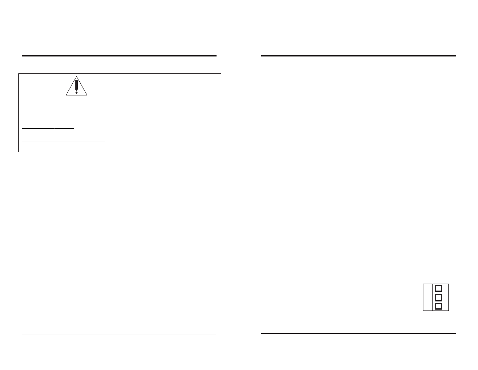
For balanced audio units, the Phoenix connectors may be removed while
making the screw connections.
When installing balanced audio connections, use the center pin for the common
or ground wire. The top or bottom pin may be used for either +
or-, however the connections must be consistent throughout.
2.3 INST ALLA TION
The RS16x16HB is designed to be mounted in a standard 19” rack panel; it is
10.5 inches, or six standard units, high.
Page 3 Page 4
Phoenix connector
C
for Balanced
Audio
 Loading...