

Knowles KAS-33100-0004 MUSKIE User Manual
USERS GUIDE
KAS-33100-0004 “MUSKIE” MICROPHONE
EVALUATION KIT
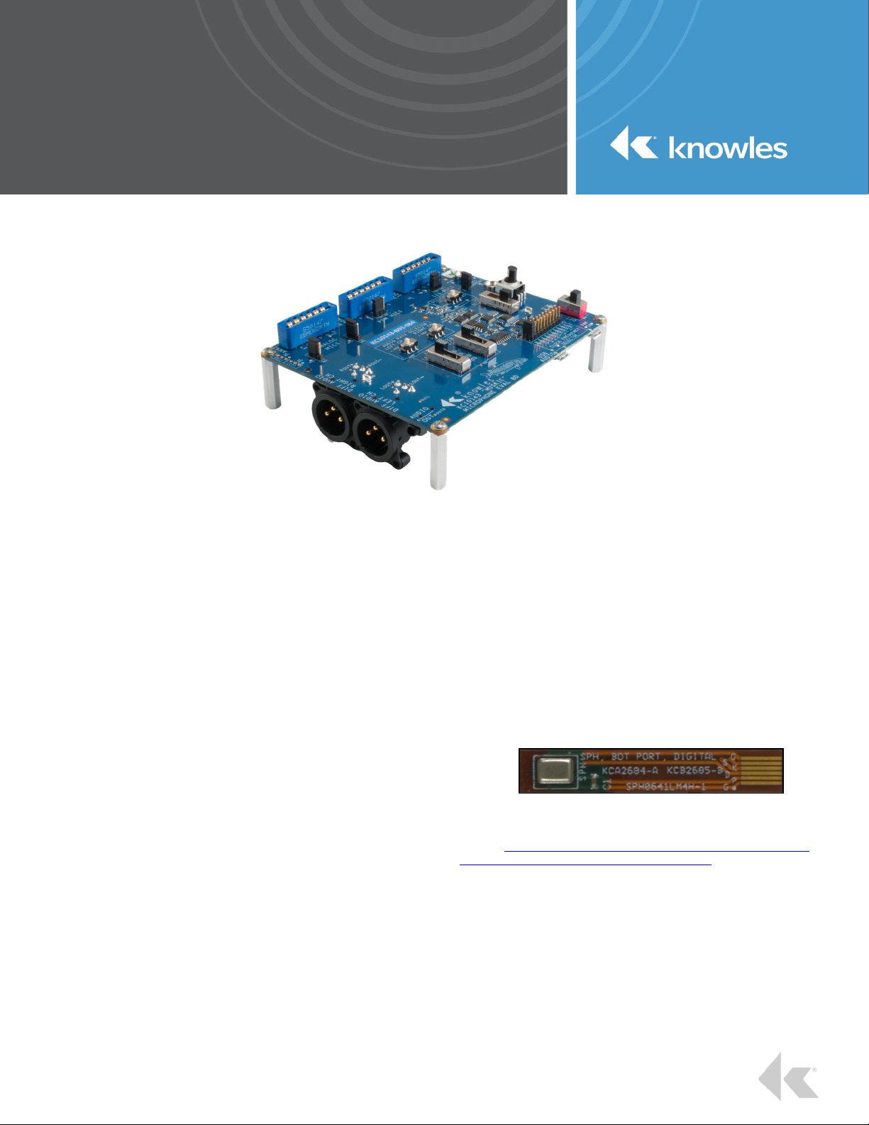
Figure 1: KC10143 Muskie Assembly
KIT DESCRIPTION
The KAS-33100-0004 Muskie microphone evaluation kit allows for
simple and easy evaluation of Knowles SiSonic™ MEMS microphones.
• Evaluate two input channels of audio from multiple MEMS
microphone types.
• Microphone types include single and differential Analog
MEMS microphones, Digital PDM MEMS microphones, and
Digital I2S MEMS microphones.
• Wide dynamic range (varies with microphone types and
audio path).
• Selectable Clock Frequencies, Voltages, and Gains.
• Multiple Audio Outputs – XLR, 3.5mm Headset Jack, USB
Audio.
SIMPLE QUICK START
1. Place suitable microphone assembly correctly into socket.
2. Select audio path and audio signal level.
3. Select Mic voltage and digital clock (if applicable).
4. Connect desired output (XLR, Headset, or USB).
5. Connect USB Cable and turn Power On.
KIT CONTENTS
•
KC10143-xxx Muskie Evaluation Board (Note: xxx denotes
assembly revision number)
•
USB A to USB Micro cable power cable
•
KCA2733 Flex Adapter Assembly (3 Total)
Note: The evaluation kit requires assembled MEMS
microphones. Usable assemblies include microphones
mounted to “flex” circuit cards or coupon boards. The kit
does NOT include assembled Knowles MEMS microphones.
Microphone assemblies are available separately from a
Knowles distributer.
Figure 2: Mic on Flex Assembly Example
For additional Muskie evaluation kit information, electrical
documentation, or flex circuit assembly information visit the Knowles
website. https://www.knowles.com/subdepartment/evaluation-kits/dpt-
microphones/subdpt-sisonic-surface-mount-mems.
The Muskie evaluation kit is for the evaluation of the Knowles
Electronics’ line of MEMS microphones. In some instances the eval kit
may limit overall microphone performance.
THE KITS’ INTENDED USE IS TO SUPPORT R&D
ACTIVITIES, AND IS NOT INTENDED FOR QUALIFICATION
OR PRODUCTION TEST USE.
SiSonic, Knowles and the logo are trademarks of Knowles Electronics, LLC.
knowles.com | KAS-33100-0004 Muskie Microphone Evaluation Kit
©2019, Knowles Electronics, LLC, Itasca, IL, USA, All Rights Reserved.
KNOWLES – KAS-33100-0004 “MUSKIE” MICROPHONE EVALUATION KIT USERS GUIDE
BLOCK DIAGRAM
POWER SUPPLIES
Dig
Mic1
Dig
Mic2
I2S
Mic1
I2S
Mic2
USB
Micro B
MicVDD
MicVDD
I2S Data
LSCLK
WS
PDM Data
Mic Clk
I2S Data
VBUS
Voltage Level
WS
LSCLK
shifter
74AVC6T622
FILTVBUS
Mic Clk
ADJ VDD
SELECTABLE
PDM -> I2S
Converter
Max
BW=37.5KHz
@4.8MHz
SData
AU7002
Select PDM
Select I2S
VDD
RT6150
800mA
LDK220
PDM Data
I2S Data
3.3v
1.8V
2.75V
3.3V
LRCLK
BCLK
Digital Data
Selector
74LVC157
3D3
Source
Current
27MHz
XTAL
TPS65133
SCLK
LRCLK
BCLK
SDIN
CURRENT
0.0
MK2705
AUDIO CLK
SOURCE
19.2MHz
XTAL
192KHz
24bit D/A
PCM1794
SENSE
+5VA
-5VA
OPA1632
MicVDD
CLOCK
GENERATOR
Base Clock
Freq Sel
MCLK
74LVC157
CLK DIVIDER
CIRCUITS
FREQ SELEC T
JUMPER
Ana/Dig
Selector
Ana/Dig
Selector
LOUT+
LOUT-
BCLK
LRCLK
SCLK
RST
2
ANA
Mic1
ANA
Mic2
MicVDD
Single/Diff
Selector
Single/Diff
Selector
LOUT+
LOUT-
LT6232
+19db
Selectable Attenuation
0dB, -4dB, -15dB, -19dB
OPA1632
OPA1632
Selectable Attenuation
0dB, -4dB, -15dB, -19dB
USB CODEC
PCM2900CDB
BW = 48KHz
MAX9722A
+0db
LT6232
1
3
2
1
3
2
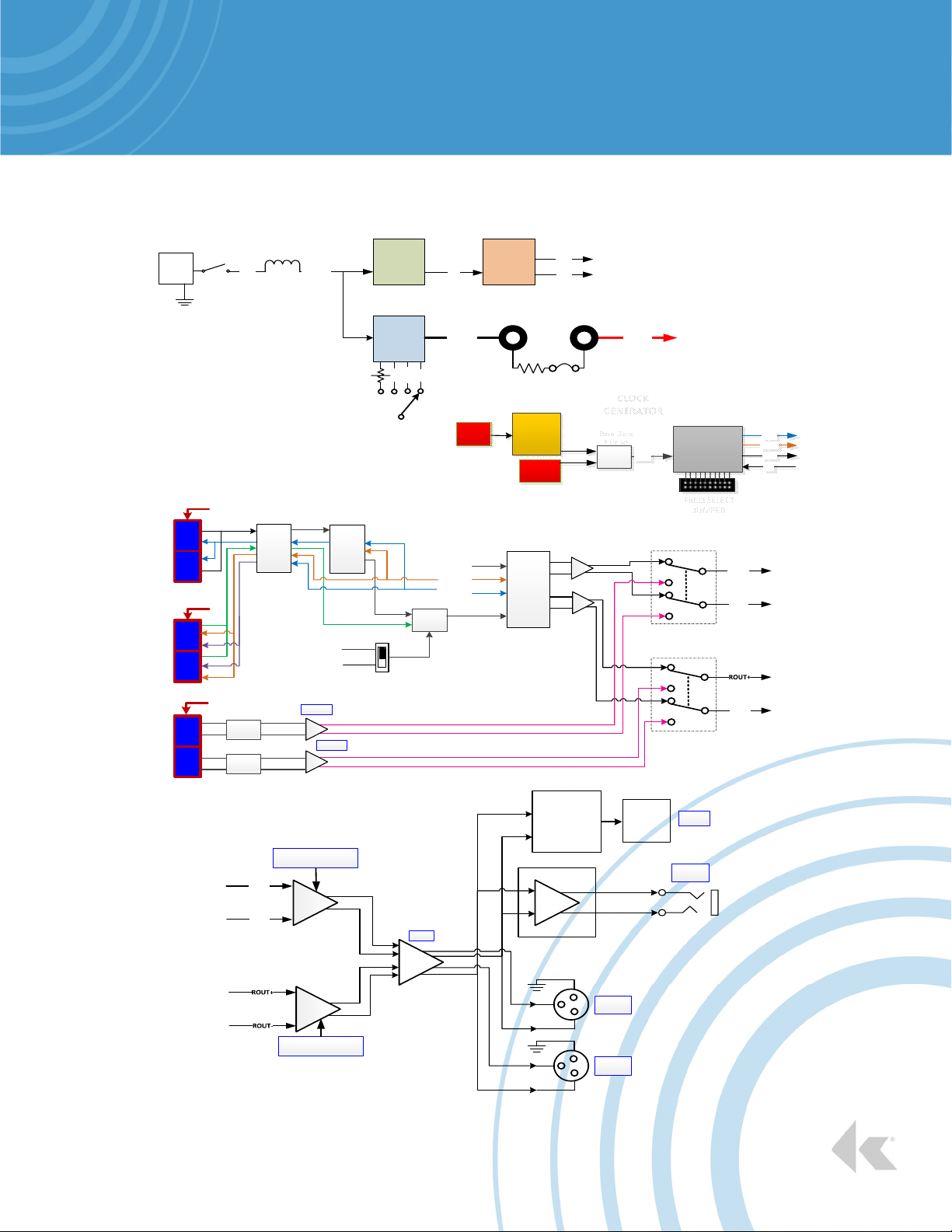
Figure 3: KC10143 Muskie Board Block Diagram
Left Diff
Audio
Right Diff
Audio
USB Micro B
Connector
USB
Audio
Headset
Jack
ROUT-
knowles.com | KNOWLES – KAS-33100-0004 “MUSKIE” MICROPHONE EVALUATION KIT USERS GUIDE
©2019, Knowles Electronics, LLC, Itasca, IL, USA, All Rights Reserved.
2 SiSonic, Knowles and the logo are trademarks of Knowles Electronics, LLC.

KNOWLES – KAS-33100-0004 “MUSKIE” MICROPHONE EVALUATION KIT USERS GUIDE
3
Analog M ic
Type
Selectors
Analog/Digital
Mic Type
Select ors
Right Channel
Audio Output
Left Channel
Audio Output
Headset Jack
Audio Output
12
13
14
Analog
Mic1
10
Analog
Mic1
10
Digital
Mic1
Digital
Mic2
Digital
MIC
Select or
8899
18 18
11
15
16
I2S Mic2I2S Mic1
77
Dual Mic
Test
Jumpers
5
6
MIC
Current
5
4
Adjustable
VDD
3
VDD
Select or
1
Power
Switch
17
Audio Gain
Selectors
Figure 4: KC10143 Muskie Functional Description
Digital M ics
Clock Frequen cy
Selector
FUNCTIONAL DESCRIPTION
1.
Main Power Switch
Slide switch. When placed in the ON position will enable the
internal voltage regulators and support circuitry. If all internal
supplies power up correctly the POWER GOOD LED will
turn on.
2.
USB connector for main power.
USB Micro B connector. Source power for Muskie board.
Knowles recommends using a USB based battery similar to
Insignia model # MB5202B for supplying clean power to kit.
3.
Microphone VDD Selector
Slide switch allows microphone voltage selection. Supports
common microphone voltages, +3.3V, +2.75V, and +1.8V.
The ADJ selection generates unique VDD voltages.
4.
Adjustable VDD
Setting the VDD SELECTOR to ADJ enables the VDD-ADJ
3 SiSonic, Knowles and the logo are trademarks of Knowles Electronics, LLC.
knowles.com | KNOWLES – KAS-33100-0004 “MUSKIE” MICROPHONE EVALUATION KIT USERS GUIDE
©2019, Knowles Electronics, LLC, Itasca, IL, USA, All Rights Reserved.
USB Micro B
Audio
Connector
potentiometer to generate a custom VDD voltage. The
adjustable voltage range is from ~+1.6V to ~+3.65V.
Refer to microphone specifications for acceptable input
voltages.
5.
MIC Current Jacks
Banana jack compatible, for measuring current using an
external current meter. Note: remove jumper labeled
BYPASS to enable.
6.
Digital MIC Selector
Sets signal path for digital microphones. Select between
PDM digital and I2S digital.
2
USB Micro B
Power
Connector
KNOWLES – KAS-33100-0004 “MUSKIE” MICROPHONE EVALUATION KIT USERS GUIDE
7.
I2S Digital Mic Connector
The socket connector can accommodate a maximum of two
coupons. Orient the flex adapter board (KCA2733) to align
the “P O G” markings with the “P O G” markings on the
Muskie board.
8.
PDM Digital Mic Connector
The socket connector can accommodate a maximum of two
coupons. Orient the flex adapter board (KCA2733) to align
the “P O G” markings with the “P O G” markings on the
Muskie board.
9.
Analog Mic Connector
The socket connector can accommodate a maximum of two
coupons. Orient the flex adapter board (KCA2733) to align
the “P O G” markings with the “P O G” markings on the
Muskie board.
10.
Analog Mic Type Selection Jumper
Select between Analog Differential Mic and Analog Single
ended Mic. Left jumper is selector for ANA1 connector
socket. Right jumper is selector for ANA2 connector socket.
11.
Analog/Digital Mic Type Selector
Select independently left and right channels between analog
or digital microphone paths.
12.
Right Channel Audio Output
Right channel differential analog audio output. Audio is
output thru a male XLR connector with the following pinouts.
Pin 1 – GND
Pin 2 – Right channel positive audio signal
Pin 3 – Right channel negative audio signal
13.
Left Channel Audio Output
Left channel differential analog audio output. Audio is output
thru a male XLR connector with the following pinouts.
Pin 1 – GND
Pin 2 – Left channel positive audio signal
Pin 3 – Left channel negative audio signal
14.
Headset Audio Output Jack
3.5mm standard analog headset jack passing stereo audio.
15.
Audio Level Selectors
Independent left and right channel gain/attenuation settings.
16.
Digital Mics Clock Frequency Selector
PDM/I2S system clock generator. Select between nine
useable digital microphone frequencies.
768KHz
1.024MHz
1.536MHz
2.048MHz
2.4MHz
2.822MHz
3.072MHz
4.096MHz
4.8MHz
NONE – Disables the clock generator circuit.
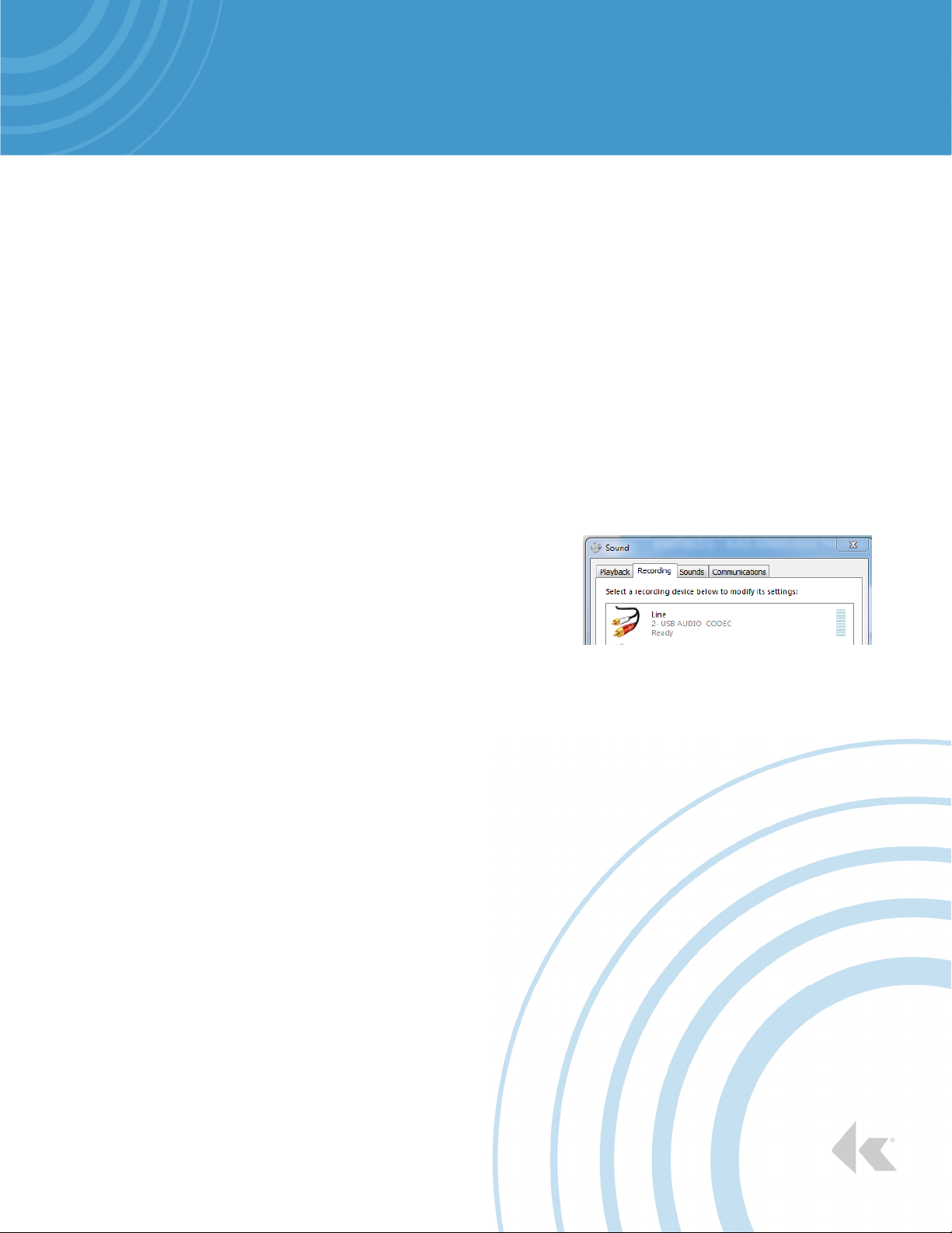
17.
USB Audio Connector
USB Micro B connector for steaming USB audio to a PC.
The Muskie board uses a generic Windows 7 USB audio
driver. No external software driver installation nessessary.
When connected and powered the device will appear as an
USB Audio Codec under the Recording tab of the Sound
window.
Figure 5: PC Sound Window
18.
Dual Mic Test Jumpers
PDM2 and I2S2 sockets VDD pin can be set to VDD or
GND, independent of PDM1 or I2S1 sockets. Used for
stereo Mic VDD testing.
4
knowles.com | KNOWLES – KAS-33100-0004 “MUSKIE” MICROPHONE EVALUATION KIT USERS GUIDE
©2019, Knowles Electronics, LLC, Itasca, IL, USA, All Rights Reserved.
4 SiSonic, Knowles and the logo are trademarks of Knowles Electronics, LLC.
 Loading...