

KNOVA KN DP-2000 Operator's Manual
KN DP-2000

TABLE OF CONTENTS
Product specifications ......................................................... 1
Proposition 65 warning ........................................................ 1
.
Power tool safety ................................................................. 1
Drill press safety .................................................................. 2
Electrical requirements and safety ....................................... 3
Carton contents ................................................................... 4
Know your drill press ........................................................... 5
PRODUCT SPECIFICATIONS
Motor: 1/4 H.P. 120 V. 60 Hz.
Spindle taper: JT 33
Capacity: 1/2” (0 - 13 mm)
Speeds: (5) 800 - 3,450 R.P.M.
Chuck: 1/2” (13 mm)
Swing: 8” (203.2 mm)
PROPOSITION 65 WARNING
Glossary and adjustments ................................................. 6
Assembly and adjustments ................................................ 6
Operation ........................................................................... 10
Maintenance ...................................................................... 13
Troubleshooting guide ....................................................... 14
Parts list ............................................................................. 15
Spindle travel: 2” (50.8 mm)
Overall height: 22-5/8” (574.6 mm)
Column diameter: 1-13/16” (46 mm)
Table size: 6-5/16” x 7-1/4” (160 x 158 mm)
Base size: 12-3/16” x 7-3/4” (310 x 196 mm)
Some dust created by power sanding, sawing, grinding, drilling and other construction activities contains chemicals
(known to the State of California) to cause cancer, birth defects or other reproductive harm. Some examples of these
chemicals are:
•Lead based paints
•Crystalline silica from bricks, cement and other masonry products
•Arsenic and chromium from chemically treated lumber
Your risk from these exposures varies, depending on how often you do this type of work. To reduce your exposure to
these chemicals, work in a well-ventilated area and work with approved safety equipment, such as dust masks that are
specially designed to filter out microscopic particles.
POWER TOOL SAFETY:
Before using your drill press, it is critical that you read and understand these safety rules. Failure to follow these rules could
result in serious injury or damage to the drill press.
Good safety practices are a combination of common sense, staying alert and understanding how to use your power
tool. To avoid mistakes that could cause serious injury, do not plug in your power tool until you have read and understood the following safety rules:
1. READ and become familiar with the entire instruction manual. LEARN the tool’s application, limitations and possible
hazards.
2. KEEP GUARDS IN PLACE and in work order.
3. DON’T USE IN DANGEROUS ENVIRONMENT. Don’t use
power tools in damp or wet locations, or expose them to rain.
Keep work area well lighted.
4. DO NOT use power tools in the presence of flammable
liquids or gases.
5. KEEP WORK AREA CLEAN. Cluttered areas and benches
invite accidents.
6. KEEP CHILDREN AWAY. All visitors should be kept a safe
distance from work area.
7. DON’T FORCE THE TOOL. It will do the job better and
safer at the rate for which it was designed.
8. USE THE RIGHT TOOL. Do not force tool or attachment to
do a job for which it was not designed.
9. WEAR PROPER APPAREL. Do not wear loose clothing,
gloves, neckties, rings, bracelets, or other jewellery, that may
get caught in moving parts. Non-slip footwear is recommended. Wear protective hair covering to contain long hair.
1

POWER TOOL SAFETY:
10. WEAR A FACE MASK OR DUST MASK. Drilling operation
produces dust.
11. DISCONNECT TOOLS before servicing; when changing
accessories such as blades, bits, cutters, and the like.
12. REDUCE THE RISK OF UNINTENTIONAL STARTING.
Make sure switch is in OFF position before plugging in.
13. USE RECOMMENDED ACCESSORIES. Consult the Operator’s Manual for recommended accessories. The use of improper accessories may cause serious injury.
14. REMOVE ADJUSTING KEYS AND WRENCHES. Form the
habit of checking to see that keys and adjusting wrenches are
removed from tool before turning it ON.
15. NEVER LEAVE TOOL RUNNING UNATTENDED. Turn power OFF. Don’t leave tool until it comes to a complete stop.
16. NEVER STAND ON TOOL. Serious injury could occur if
the tool is tipped or if the cutting tool is unintentionally contacted.
17. DON’T OVERREACH. Keep proper footing and balance at
all times.
18. MAINTAIN TOOLS WITH CARE. Keep tools sharp and
clean for best and safest performance. Follow instructions for
lubricating and changing accessories.
19. CHECK FOR DAMAGED PARTS. Before further use of the
tool, a guard or other part that is damaged should be care-
fully checked to determine that it will operate properly and
perform its intended function – check for alignment of moving
parts, binding of moving parts, breakage of parts, mounting,
and any other conditions that may affect its operation. A guard
or other part that is damaged should be properly repaired or
replaced.
20. MAKE WORKSHOP CHILD PROOF with padlocks, master switches, or by removing starter keys.
21. DO NOT operate the tool if you are under the influence of
any drugs, alcohol or medication that could affect your ability
to use the tool properly.
22. Dust generated from certain
material can be hazardous to your
health. Always operate the drill
press in a well-ventilated area and
provide for proper dust removal.
Use dust collection system
whenever possible.
23. ALWAYS WEAR EYE PROTECTION. Any drill press could
throw foreign objects into the eyes that could cause permanent eye damage. ALWAYS wear Safety Goggles (not glasses) that comply with ANSI Safety standard Z87.1 Everyday
eyeglasses have only impact-resistant lenses. They ARE NOT
safety glasses.
NOTE: Glasses or goggles not in compliance with ANSI Z87.1
could cause serious injury.
DRILL PRESS SAFETY
1. THE DRILL PRESS MUST BE BOLTED securely to a workbench. In addition, if there is any tendency for the drill press to
move during certain operations, bolt the workbench to the floor.
2. THIS DRILL PRESS is intended for use in dry conditions,
indoor use only.
3. WEAR EYE PROTECTION. USE face or dust mask along
with safety goggles if drilling operation is dusty. USE ear protectors, especially during extended periods of operation.
4. DO NOT wear gloves, neckties, or loose clothing.
5. DO NOT try to drill material too small to be securely held.
6. ALWAYS keep hands out of the path of a drill bit. Avoid awkward hand positions where a sudden slip could cause your
hand to move into the drill bit.
7. DO NOT install or use any drill bit that exceeds 175 mm
(7”) in length or extends 150 mm (6”) below the chuck jaws.
They can suddenly bend outward or break.
8. DO NOT USE wire wheels, router bits, shaper cutters, circle (fly) cutters, or rotary planers on this drill press.
9. WHEN cutting a large piece of material make sure it is fully
supported at the table height.
10. DO NOT perform any operation freehand. ALWAYS hold
the workpiece firmly against the table so it will not rock or
twist. Use clamps or a vice for unstable workpiece.
11. MAKE SURE there are no nails or foreign objects in the
part of the workpiece to be drilled.
12. CLAMP WORKPIECE OR BRACE against the left side of
the column to prevent rotation. If it is too short or the table is
tilted, clamp solidly to the table.
13. IF THE WORKPIECE overhangs the table such that it will
fall or tip if not held, clamp it to the table or provide auxiliary
support.
14. SECURE WORK. Use clamps or vice to hold the work
when practical. It’s safer than using your hand and it frees
both hands to operate tool.
15. WHEN using a drill press vice, always fasten to the table.
16. MAKE SURE all clamps and locks are firmly tightened before drilling.
17. SECURELY LOCK the head and table support to the column, and the table to the table support before operating the
drill press.
18. NEVER turn your drill press ON before clearing the table
of all objects (tools, scraps of wood, etc.)
19. BEFORE STARTING the operation, jog the motor switch to
make sure the drill bit does not wobble or vibrate.
20. LET THE SPINDLE REACH FULL SPEED before starting
to drill. If your drill press makes an unfamiliar noise or if it
vibrates excessively, stop immediately, turn the drill press off
and unplug. Do not restart until the problem is corrected.
21. DO NOT perform lay out assembly or set up work on the
table while the drill press is in operation.
2
DRILL PRESS SAFETY
22. USE RECOMMENDED SPEED for drill accessory and
workpiece material. SEE INSTRUCTIONS that come with the
accessory.
23. WHEN DRILLING large diameter holes, clamp the workpiece firmly to the table. Otherwise, the bit may grab and spin
the workpiece at high speed. DO NOT USE fly cutters or multiple-part hole cutters, as they can come apart or become unbalanced in use.
24. MAKE SURE the spindle has come to a complete stop
before touching the workpiece.
25. TO AVOID INJURY from accidental starting, always turn
the switch OFF and unplug the drill press before installing or
removing any accessory or attachment or making any adjustment.
26. KEEP GUARDS IN PLACE and in working order.
27. USE ONLY SELF-EJECTING TYPE CHUCK KEY as provided with the drill press.
ELECTRICAL REQUIREMENTS AND SAFETY
IN THE EVENT OF A MALFUNCTION OR BREAKDOWN,
grounding provides a path of least resistance for electric currents and reduces the risk ofelectric shock. This tool is equipped
with an electrical cord that has an equipment-grounding conductor and a grounding plug. The plug must be plugged into a
matching receptacle that is properly installed and grounded in
accordance with all local codes and ordinances.
DO NOT MODIFY THE PLUG PROVIDED. If it will not fit the
receptacle, have the proper receptacle installed by a qualified
electrician.
IMPROPER CONNECTION of the equipment grounding conductor can result in risk of electric shock. The conductor with
the green insulation (with or without yellow stripes) is the
equipment grounding conductor. If repair or replacement of
the electrical cord or plug is necessary, DO NOT connect the
equipment grounding conductor to a live terminal.
Use a separate electrical circuit for your tools. This circuit must
not be less than #12 wire and should be protected with a 15
Amp time lag fuse. Before connecting the motor to the power
line, make sure the switch is in the OFF position and electric
current is rated the same as the current stamped on the motor
nameplate. Running at a lower voltage will damage the motor.
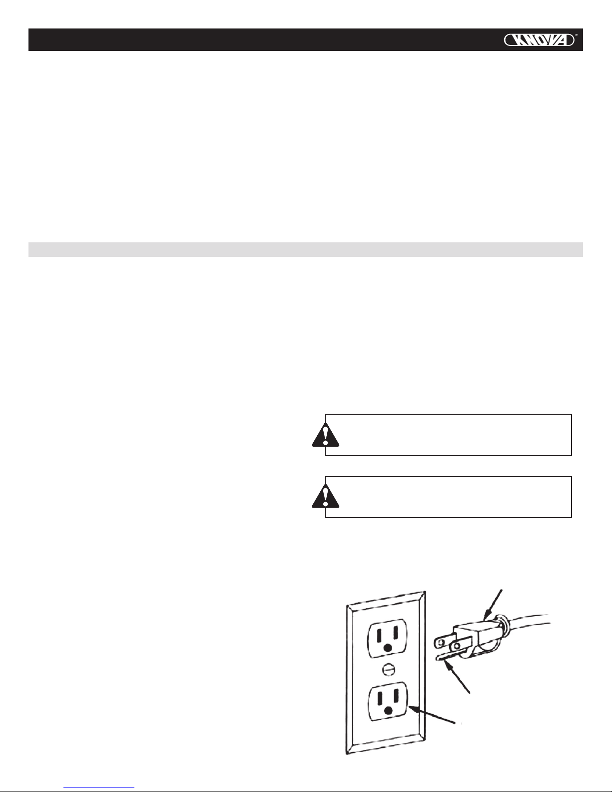
This drill press is intended for use on a circuit that has a receptacle like the one illustrated below. This shows a 3-prong
electrical plug and receptacle that has a grounding conductor.
The Canadian Electrical Code prohibits the use of adapters.
CAUTION In all cases, make certain the receptacle
is properly grounded. If you are not sure, have a
qualified electrician check the receptacle.
CHECK with a qualified electrician or service person if you do
not completely understand the grounding instructions, or if you
are not certain the tool is properly grounded.
USE ONLY THREE-WIRE EXTENSION CORDS THAT HAVE
THREEPRONGED GROUNDING PLUGS WITH THREE-POLE
RECEPTACLES THAT ACCEPT THE TOOL’S PLUG. REPAIR OR
REPLACE DAMAGED OR WORN CORDS IMMEDIATELY.
GUIDELINES FOR EXTENSION CORDS
Make sure your extension cord is in good condition. Use an
extension cord heavy enough to carry the current your product
will draw. An undersized cord will cause a drop in line voltage resulting in loss of power, overheating and burning out of
the motor. The table on the right shows the correct size to use
depending on cord length and nameplate ampere rating. If in
doubt, use the next heavier gauge. The smaller the gauge number, the heavier the cord.
Be sure your extension cord is properly wired and in good
condition. Always replace a damaged extension cord or have
it repaired by a qualified person before using it. Protect extension cords from sharp objects, excessive heat and damp or wet
areas.
WARNING
This drill press is for indoor use only. Do not expose
to rain or use in damp locations.
Fig. 1
Three-Pronged Plug
Grounding Prong
Properly Grounded
Three-Pronged Receptacle
3
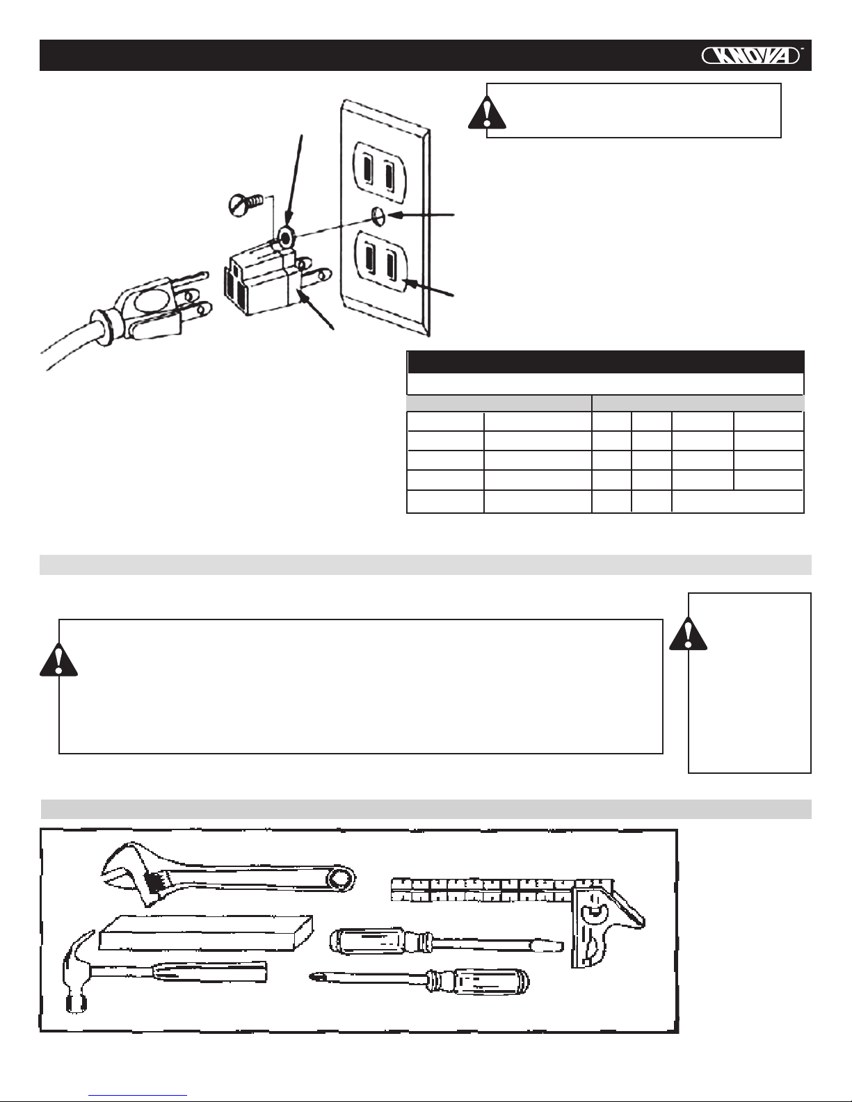
ELECTRICAL REQUIREMENTS AND SAFETY
Fig. 2
Grounding Lug
Adapter
CAUTION
This drill must be grounded while in use to
protect the operator from electric shock.
Make sure this is
connected to a
known ground.
Two-Pronged
Receptacle
MINIMUM GAUGE FOR EXTENSION CORDS (AWG)
(When using 120 volts only)
Ampere Rating Total length of Cord
More Than Not More Than 25ft. 50ft. 100ft. 150ft.
0 6 18 16 16 14
6 10 18 16 14 12
10 12 16 16 14 12
12 16 14 12 Not Recommended
CARTON CONTENTS
UNPACKING AND CHECKING CONTENTS
WARNING
If any part is missing or damaged, do not plug the drill press in until the missing or damaged
part is replaced, and assembly is complete.
Carefully unpack the drill press and all its parts, and compare against the list below.
To protect the drill press from moisture, a protective coating has been applied to the machined
surfaces. Remove this coating with a soft cloth moistened with a substance such as WD-40.
TOOLS NEEDED FOR ASSEMBLY
WARNING
To avoid fire or
toxic reaction,
never use gasoline, naphtha,
acetone, lacquer thinner or
similar highly
volatile solvents to clean
the drill press.
NOT SUPPLIED
•Adjustablewrench
•Hammerand
block of wood
•Combination
square
•Screwdrivers
4
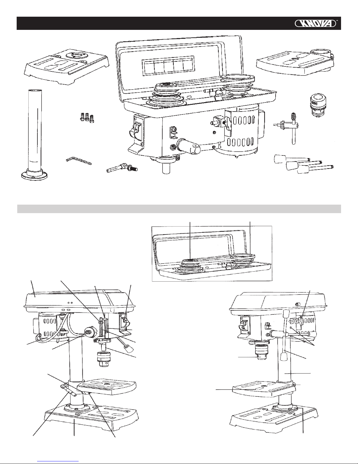
CARTON CONTENTS
Base
Table
Chuck key
Bolts (3)
Hex key (3 mm.)
Support lock handle
KNOW YOUR DRILL PRESS
Cover
Stop nuts
Depth
pointer
ON/OFF
swich w/key
Head/motor assembly
Spindle pulley
Cover
Chuck
Feed handles (3)
Motor pulley
Belt tension
knob
Motor
Support lock
handle
Feed
spring
Base
Bevei lock
Depth scale
Feed stop rod
Spindle
Head lock
screws
Chuck
Table
Column support
Feed handle
Column
Table support
5
GLOSSARY OF TERMS
BASE – Supports drill press. For additional stability, holes are
provided in base to bolt drill press to floor.
(See: SPECIFIC SAFETY INSTRUCTIONS FOR THE DRILL
PRESS.)
BACKUP MATERIAL – A piece of scrap wood placed between
the workpiece and table. The backup board prevents wood in
the workpiece from splintering when the drill passes through
the backside of the workpiece. It also prevents drilling into
the tabletop.
BELT TENSION – Refer to ASSEMBLY AND ADJUSTMENTS:
BELT TENSION, page12.
BELT TENSION LOCK KNOB – Tightening the knob locks the
motor bracket support maintaining correct belt distance and
tension.
BEVEL SCALE – Shows degree of table tilt for bevel operations. Scale is mounted on side of arm.
CHUCK – Holds drill bit or other recommended accessory to
perform desired operations.
CHUCK KEY – A self-ejecting chuck key that will pop out of
the chuck when you let go of it. This action is designed to help
prevent throwing of the chuck key from the chuck when the
power is turned ON. Do not use any other key as a substitute;
order a new one if damaged or lost.
COLUMN – Connects head, table, and base on a one-piece
tube for easy alignment and movement.
COLUMN SUPPORT – Supports column, and provides mounting holes for column to base.
DEPTH SCALE – Indicates depth of hole being drilled.
DEPTH SCALE POINTER – Indicates the drilling depth by
pointing to the depth scale.
DEPTH SCALE LOCK – Locks the depth scale to selected
depth.
DRILL BIT – The cutting tool used in the drill press to make
holes in a workpiece.
DRILL ON/OFF SWITCH – Has locking feature. This feature
is intended to help prevent unauthorized and possible hazardous use by children and others.
DRILLING SPEED – Changed by placing the belt in any of the
steps (grooves) in the pulleys. See Spindle Speed inside belt
guard.
FEED HANDLE – Moves the chuck up or down. One or two of
the handles may be removed if the workpiece is an unusual
shape and it interferes with the handles.
HEAD LOCKS – Locks the head to the column. ALWAYS lock
head in place while operating the drill press.
REVOLUTION PER MINUTE (R.P.M.) – The number of turns
completed by a spinning object in one minute.
SPINDLE SPEED – The R.P.M. of the spindle.
SPRING CAP – Adjusts quill spring tension.
SUPPORT LOCK – Tightening locks table support to column.
Always have it locked in place while operating the drill press.
TABLE – Provides working surface to support workpiece.
TABLE BEVEL LOCK – Locks the table in any position from
0° - 45°.
TABLE LOCK – Locks the table after it is rotated to various
positions.
TABLE SUPPORT – Rides on column to support table arm and
table.
WORKPIECE – Material being drilled.
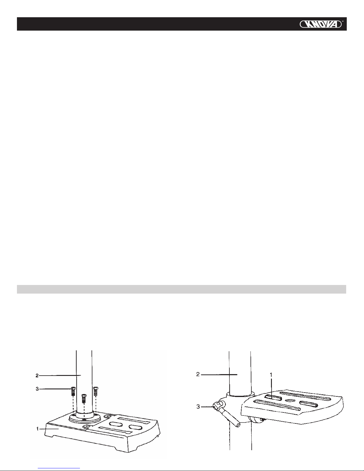
ASSEMBLY AND ADJUSTMENTS
BASE/COLUMN (FIG. A)
1. Set the base (1) on the floor.
2. Place the column (2) on the base, aligning the holes in the
column support with the base holes.
3. Install a bolt (3) in each column support hole, and tighten
with an adjustable wrench.
Fig. A
TABLE (FIG. B)
1. Slide table assembly (1) down the column (2), until it rests
on the base.
2. Install the lock handle (3) in the threaded hole.
3. Slide the table up the column to working height and hand
tighten the lock handle to secure the table in place.
Fig. B
6

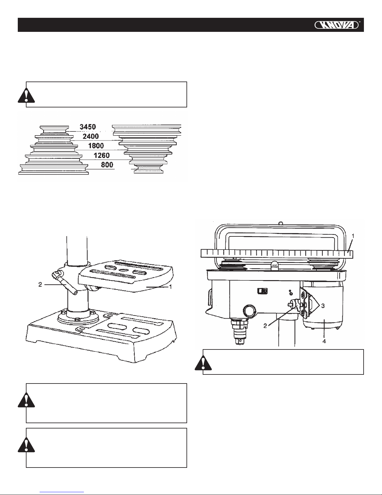
ASSEMBLY AND ADJUSTMENTS
HEAD/MOTOR ASSEMBLY (FIG. C)
CAUTION:
The head/motor assembly (1) is heavy. Lift carefully.
1. Lift above the column (2), slide down the column as far as
it will go.
2. Line the head up with the base.
3. Tighten the two locking screws (3) with the hex key
Fig. C
CHUCK (FIG. E, F)
1. Inspect and clean the hole in the chuck (1) and the spindle (2).
2. Remove all grease, coatings, and particles from the chuck
and spindle surfaces with a clean cloth moistened with a nonoil based solution such as Rubbing Alcohol.
3. Open the chuck jaws (3), by turning the chuck barrel clockwise, and make sure the jaws are completely recessed inside
the chuck.
4. Seat the chuck (1) (Fig. F) onto the spindle by placing a
block of wood under the chuck, and tapping the wood with
a hammer, or tap the chuck with a rubber mallet or plastictipped hammer.
5. Do not tap the chuck with a metal hammer.
Fig. E
FEED ASSEMBLY (FIG. D)
1. Thread the feed handles (1) into the holes on the feed hub (2).
2. Hand tightens.
FEED ASSEMBLY (FIG. D)
1. Thread the feed handles (1) into the holes on the feed hub (2).
2. Hand tighten.
WARNING
Disconnect the drill press from the power source before
installing, adjusting, or removing the chuck.
MOUNTING THE DRILL PRESS (FIG. G)
The drill press must be securely fastened by the two base
holes to a stand or workbench with heavy-duty fasteners. This
will prevent the drill press from tipping over, sliding, or walking during operation.
IMPORTANT: If the stand or workbench has a tendency to
move during operation, fasten it securely to the floor.
1. Drill press base
2. Bolt
3. Flat washer
4. Rubber washer
5. Work surface
6. Flat washer
7. Lock washer
8. Hex nut
9. Jam nut
Fig. D
Fig. G
7
ASSEMBLY AND ADJUSTMENTS
SPINDLE SPEEDS (Fig. H)
This drill offers 5 spindle speeds from 800 to 3450 R.P.M.
The highest speed is obtained when the belt is positioned on
the largest motor pulley step and the smallest spindle pulley
step.
WARNING
Disconnect the drill press from the power source before making any adjustments.
Spindle
TO MOVE THE TABLE (FIG. I)
1. Raise or lower the table (1) by loosening the support lock
handle (2).
2. Move the table to the desired position and tighten the support lock handle.
Motor
Fig. H
ALIGNING THE BELT PULLEYS (FIG. K)
Open the head cover of the Drill Press. Check alignment of
the pulleys with a straight edge (1) such as a framing square,
a level, or a piece of a wood. Lay the straight edge across the
top of the pulleys. If all three pulleys are NOT aligned:
1. Release belt pressure by loosening the belt tension lock
knobs (2) on either side of the head, counter clockwise.
2. Loosen the motor mount nuts (3). Lift or lower the motor (4)
until the pulleys are in line.
3. Tighten the motor mount nuts (3) using an adjustable wrench.
NOTE: To avoid rattles or other noise, the motor housing
should not touch the lower belt guard housing.
4. Retighten the belts by pulling the motor (4) toward the drill
press head, until the belt deflects approximately 1/2 inch
when pressed in the centre.
NOTE: Refer to the chart inside the belt guard cover for recommended drilling speeds and belt/pulley positions.
5. Lock the belt tension lock knobs (2) by turning clockwise.
NOTE: When the belts are new, it may be difficult to move the
belts. As the machine is used, the belts will gain more elasticity and will be easier to adjust.
Fig. I
DRILL PRESS ADJUSTMENTS
CAUTION
All the adjustments for the operation of the drill press
have been completed at the factory. Due to normal
wear and use, some occasional readjustments may
be necessary.
WARNING
To avoid injury from an accidental start, ALWAYS make
sure the switch is in the OFF position, the switch key
is removed, and the plug is not connected to the power source outlet before making belt adjustment.
Fig. K
WARNING
To prevent personal injury, always disconnect the plug
from the power source when making any adjustment
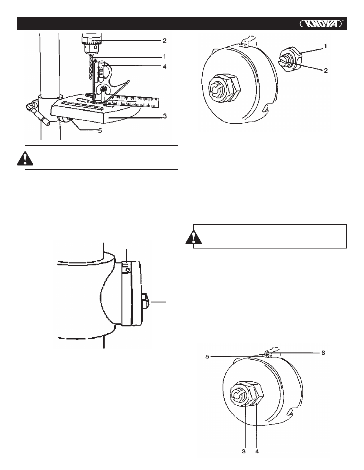
SQUARING TABLE TO HEAD (FIG. L)
1. Insert a 3” drill bit (1) into the chuck (2), tighten by turning
the chuck barrel counter clockwise.
2. Place a combination square (4) on the table (3) as shown.
The drill bit should be parallel to the straight edge of the
square.
3. If an adjustment is needed, loosen the bevel lock (5) with
a wrench.
4. Square the table to the bit by tilting the table.
5. Tighten the bevel lock when square.
8
ASSEMBLY AND ADJUSTMENTS
Fig. N
Fig. L
WARNING
Disconnect the drill press from the power source before making any adjustments.
TO TILT THE TABLE SCALE (FIG. M)
NOTE: The table is not shown in Fig. M for clarity of illustration.
1. Loosen the bevel lock (1) with a wrench.
2. Tilt the table to the desired angle, using the bevel scale (2)
as a basic guide.
3. Tighten the bevel lock.
2
1
Fig. M
QUILL RETURN SPRING (FIG. O)
The quill return spring may need adjustment if the tension
causes the quill to return too rapidly or too slowly.
1. Lower the table for additional clearance.
2. Place a screwdriver in the lower front notch (1) of the spring
cap (2). Hold it in place while loosening and removing only the
outer jam nut (3).
3. With the screwdriver still engaged in the notch, loosen the
inner nut (4) just until the notch (5) disengages from the boss
(6) on the drill press head.
CAUTION:
DO NOT REMOVE THIS INNER NUT, because the
spring will forcibly unwind.
4. Carefully turn the spring cap (2) counter clockwise with the
screwdriver, engaging the next notch.
5. Lower the quill to the lowest position by rotating the feed
handle in a counter clockwise direction while holding the
spring cap (2) in position.
6. If the quill moves up and down as easily as you desire,
tighten the standard nut (4) with the adjustable wrench. If too
loose, repeat steps 2 through 5 to tighten. If too tight, reverse
steps 4 and 5.
DO NOT OVERTIGHTEN and restrict quill movement.
7. Place the jam nut (3) and tighten against the standard nut
(4) to prevent the standard nut from reversing.
SPINDLE / QUILL (FIG. N)
Rotate the feed handles counter clockwise to lower spindle
to its lowest position. Hand support the spindle securely and
move it back and forth around the axis. If there is too much
play, do the following:
1. Loosen the lock nut (1).
2. Turn the screw (2) clockwise to eliminate the play, but without obstructing the upward movement of the spindle. (A little
play in the spindle is normal.)
3. Tighten the lock nut (1).
Fig. O
9
ASSEMBLY AND ADJUSTMENTS
WARNING:
To avoid injury from an accidental start, ALWAYS
make sure the switch is in the OFF position, the
switch key is removed, and the plug is not connected
to the power source outlet before making belt adjustment.
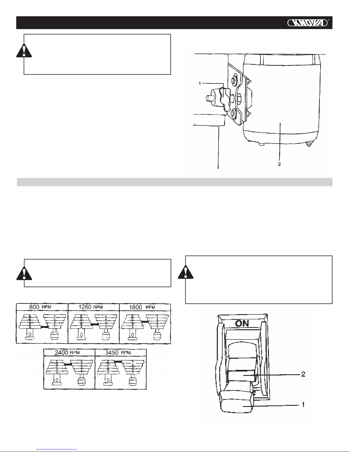
BELT TENSION (FIG. P)
Make sure pulleys are aligned properly as shown in Fig. K.
1. To unlock the belt tension, turn the belt tension lock knobs
(1) on each side of the drill press head counter clockwise.
2. Move the motor (2) toward the front of the drill press to
loosen the belt tension.
3. Position the belt on the correct pulley steps for the desired speed.
4. Pull the motor away from the drill press head until the belt
is properly tensioned.
NOTE: Belt tension is correct if the belt deflects approximately 1/2 inch when pressed at its centre.
OPERATION
BASIC DRILL PRESS OPERATIONS
SPEEDS AND BELT PLACEMENT (FIG. Q)
This drill press has 5 speeds, as listed below:
800 RPM 1260 RPM 1800 RPM
2400 RPM 3450 RPM
See inside of the pulley guard for specific placement of the
belts on the pulleys to change speeds.
WARNING:
To avoid possible injury, keep guard closed, in place,
and in proper working order while tool is in operation.
Belt / pulley position-RPM chart
5. Tighten the belt tension lock knobs (1) on each side of the
drill press head.
Fig. P
1. To turn the drill press ON, insert yellow key (1) into the slot
(2) in the centre of the switch.
2. Push the key firmly into the slot, and then push switch to
the ON position to start the drill press.
3. To turn the drill press OFF, push the switch to the down
position.
4. Remove the yellow switch key, when the saw has come to
a complete stop, by gently pulling it outward.
WARNING:
ALWAYS lock the switch OFF when the drill press
is not in use. Remove the key and keep it in a safe
place. In the event of a power failure, blown fuse, or
tripped circuit breaker, turn the switch OFF and remove the key, preventing an accidental start-up when
power comes on.
BELT. A-1 BELT. B-2
Fig. Q
BELT. D-4
BELT. E-5
BELT. C-3
ON/OFF SWITCH PANEL (FIG. R)
The ON / OFF switch has a removable, yellow plastic key.
With the key removed from the switch, unauthorized and hazardous use by children and others is minimized.
Fig. R
10
 Loading...