

KNOVA KN BTS-10W User Manual

KN BTS-10W
10
”
(254 mm)
Table saw with stand
Sierra de mesa para madera con base

TABLE OF CONTENTS
Product Specifications 2
Proposition 65 Warning 2
Power Tool Safety 3
Table Saw Safety 4
Electrical Requirements and Safety 4
Pre-assembly 5
Tools Required For Assembly 6
Carton Contents 7
PRODUCT SPECIFICATIONS
Depth of cut at 90º: 3” (76.2 mm)
Depth of cut at 45º: 2-1/2” (63.5 mm)
Saw blade carbide tipped: 10” (254 mm)
Arbor: 5/8” (15.8 mm)
Saw blade speed: 4,500 R.P.M. (no load)
Universal motor: 2.7 H.P. (maximun load) 120 V. 60 Hz.
Know Your Table Saw 7
Glossary of Terms 3
Assembly 10
Adjustments 11
Operation 12
Maintenance 12
Troubleshooting Guide 13
Parts List and Exploded Views 13
Die cast aluminum table: 26-7/64” x 17-1/8” (663 x 435 mm)
Aluminum extrusion fence: 17-7/8” x 2” (454 x 50.8 mm)
ABS miter gauge: 30º, 45º, 60º, 75º, 90º (L & R)
Machine dimensions: 27-23/64” x 26-3/16” x 38-9/16”
(695 x 665 x 980 mm)
width - depth - height
Weight: net/gross: 17.7/20 Kgs.
PROPOSITION 65 WARNING
Some dust created by power sanding, sawing, grinding, drilling and other construction activities contains chemicals
(known to the State of California) to cause cancer, birth defects or other reproductive harm. Some examples of these
chemicals are:
• Lead based paints
• Crystalline silica from bricks, cement and other masonry products
• Arsenic and chromium from chemically treated lumber
Your risk from these exposures varies, depending on how often you do this type of work. To reduce your exposure to
these chemicals, work in a well-ventilated area and work with approved safety equipment, such as dust masks that are
specially designed to filter out microscopic particles.
POWER TOOL SAFETY:
GENERAL SAFETY INSTRUCTIONS Read and understand all the instructions below before using the power tool. These
safety instructions are not meant to cover every possible condition that could occur. As with any power tool, common
sense, vigilance and due care must be used.
1. READ and become familiar with this entire Operator’s Manual. LEARN the tool’s applications, limitations and possible
hazards.
2. CAUTION Look for this symbol that identifies important
safety precautions. It means BE ALERT! YOUR SAFETY IS INVOLVED!
3. NEVER OPERATE THIS MACHINE WITHOUT THE SAFETY
GUARD IN PLACE FOR ALL THROUGH
–SAWING OPERATIONS.
5. DO NOT use power tools in the presence of flammable
liquids or gases.
6. KEEP WORK AREA CLEAN. Cluttered areas and benches
invite accidents.
7. KEEP CHILDREN AWAY. All visitors should be kept at a
safe distance from the work area.
8. DO NOT FORCE THE TOOL. It will do the job better and
safer if used at the rate for which it was designed.
4. DO NOT USE IN A DANGEROUS ENVIRONMENT such
as damp or wet locations or in the rain. Keep work area well
lighted.
9. USE THE RIGHT TOOL. Don’t force the tool or attachment
to do a job for which it is not designed.
1

10. WEAR PROPER APPAREL. DO NOT wear loose clothing,
gloves, neckties, rings, bracelets or other jewelry that may get
caught in moving parts. Non-slip footwear is recommended.
Wear protective hair covering to contain long hair.
11. WEAR A FACE MASK OR DUST MASK. Sawing, cutting
and sanding operations produce dust.
12. DISCONNECT TOOLS before servicing and when changing accessories, such as blades, cutters, etc.
13. REDUCE THE RISK OF UNINTENTIONAL STARTING.
Make sure the switch is in the OFF position before plugging
tool into the power supply.
14. USE ONLY RECOMMENDED ACCESSORIES. Consult
the Operator’s Manual for recommended accessories. The
use of improper accessories may cause injury to you or damage to the tool.
15. REMOVE ADJUSTING KEYS AND WRENCHES. Form the
habit of checking to see that keys and adjusting wrenches are
removed from the tool before turning ON.
16. NEVER LEAVE TOOL RUNNING UNATTENDED. TURN
THE POWER OFF. Do not leave the tool before the blade
comes to a complete stop.
17. NEVER STAND ON TOOL. Serious injury could occur if
the tool is tipped or if the cutting tool is unintentionally contacted.
18. DO NOT OVERREACH. Keep proper footing and balance
at all times.
20. CHECK FOR DAMAGED OR LOOSE PARTS. Check for
alignment of moving parts, binding of moving parts, loose
mounting and any other conditions that may affect its safe operation. A guard or other part that is loose or damaged should
be properly adjusted, repaired or replaced.
21. MAKE WORKSHOP CHILDPROOF with padlocks, master
switches or by removing starter keys.
22. DO NOT operate the tool if you are under the influence of
any drugs, alcohol or medication that could impair your ability
to use the tool safely.
23. USE A DUST COLLECTION SYSTEM whenever possible.
Dust generated from certain materials can be hazardous to
your health and, in some cases, a fire hazard. Always operate
the power tool in a well-ventilated area with adequate dust
removal.
24. ALWAYS WEAR EYE PROTECTION. Any power tool can
throw debris into your eyes that could cause permanent eye
damage. ALWAYS wear safety goggles (not glasses) that comply with ANSI safety standard Z87.1. Everyday glasses have
only impact resistant lenses. They ARE NOT safety glasses.
NOTE: Glasses or goggles not in compliance with ANSI Z87.1
could cause serious injury when they break.
25. DIRECTION OF FEED. Feed work into a blade or cutter
against the direction of rotation of the blade or cutter only.
26. DO NOT loan your tool to a neighbor or friend without providing him/her with the Operator’s Manual. Be sure he/she
learns the tool’s applications and possible hazards.
19. MAINTAIN TOOLS WITH CARE. Keep tools sharp and
clean for most efficient and safest performance. Follow instructions for lubricating and changing accessories.
TABLE SAW SAFETY
1. ALWAYS USE SAW BLADE GUARD, splitter and anti-kickback pawls for every through–sawing operation. Through–sawing operations are those in which the blade cuts completely
through the workpiece when ripping or crosscutting. Always
be sure blade guard is tightened securely.
2. ALWAYS HOLD WORK FIRMLY against the miter gauge or
rip fence.
3. ALWAYS USE a push stick, especially when ripping narrow
stock. Refer to ripping instructions in this Operator’s Manual
where the push stick is covered in detail. A pattern for making
your own push stick is included on page 25.
4. NEVER PERFORM ANY OPERATION FREEHAND, which
means using only your hands to support or guide the workpiece. Always use either the fence or the miter gauge to position and guide the work.
WARNING: FREEHAND CUTTING IS THE MAJOR CAUSE
OF KICKBACK AND FINGER/HAND AMPUTATIONS. NEVER
USE THE MITER GAUGE AND FENCE SIMULTANEOUSLY.
5. NEVER STAND or have any part of your body in line with
the path of the saw blade. Keep your hands out of the saw
blade path.
6. NEVER REACH behind or over the cutting tool for any reason.
7. REMOVE the rip fence when crosscutting.
8. DO NOT USE a molding head with this saw.
9. FEED WORK INTO THE BLADE against the direction of
rotation only.
10. NEVER use the rip fence as a cut-off gauge when crosscutting.
11. NEVER ATTEMPT TO FREE A STALLED SAW BLADE without first turning the saw OFF. Turn power switch OFF immediately to prevent motor damage.
12. PROVIDE ADEQUATE SUPPORT to the rear and the sides
of the saw table for long or wide workpieces.
13. AVOID KICKBACKS (work thrown back towards you) by
keeping the blade sharp, the rip fence parallel to the saw blade
and by keeping the splitter, antikickback pawls and guards in
place, aligned and functioning. Do not release work before
passing it completely beyond the saw blade. Do not rip work
2

that is twisted, warped or does not have a straight edge to
guide it along the fence. Do not attempt to reverse out of a cut
with the blade running.
14. AVOID AWKWARD OPERATIONS and hand positions
where a sudden slip could cause your hand to move into the
saw blade.
15. NEVER USE SOLVENTS to clean plastic parts. Solvents
could possibly dissolve or otherwise damage the material.
Only a soft damp cloth should be used to clean plastic parts.
16. MOUNT your table saw on a bench or stand before performing any cutting operations. Refer to ASSEMBLY on page 10.
17. NEVER CUT METALS or materials that may make hazardous dust.
18. ALWAYS USE IN A WELL-VENTILATED AREA. Remove
sawdust frequently. Clean out sawdust from the interior of the
saw to prevent a potential fire hazard. Attach a vacuum to the
dust port for additional sawdust removal.
19. NEVER LEAVE THE SAW RUNNING UNATTENDED. Do
not leave the saw until the blade comes to a complete stop.
20. FOR PROPER OPERATION follow the instructions in this
Operator’s Manual entitled OPERATION (Page 18).
NOTE: On machines with no stand or if stand is not being
used, a hole approximately 12 in. square must be cut under
saw to allow sawdust to fall through. Failure to cut this hole
will allow sawdust to build up in the motor area, resulting in a
fire hazard and potential motor damage.
ELECTRICAL REQUIREMENTS AND SAFETY
GROUNDING INSTRUCTIONS IN THE EVENT OF A MALFUNCTION OR BREAKDOWN, grounding provides a path of
least resistance for electric currents and reduces the risk ofelectric shock. This tool is equipped with an electrical cord that
has an equipment-grounding conductor and a grounding plug.
The plug must be plugged into a matching receptacle that is
properly installed and grounded in accordance with all local
codes and ordinances.
DO NOT MODIFY THE PLUG PROVIDED. If it will not fit the
receptacle, have the proper receptacle installed by a qualified
electrician.
IMPROPER CONNECTION of the equipment grounding conductor can result in risk of electric shock. The conductor with
the green insulation (with or without yellow stripes) is the
equipment grounding conductor. If repair or replacement of the
electrical cord or plug is necessary, do not connect the equipment grounding conductor to a live terminal.
CHECK with a qualified electrician or service person if you do
not completely understand the grounding instructions, or if you
are not certain the tool is properly grounded.
USE only three-wire extension cords that have threepronged
grounding plugs with three-pole receptacles that accept the
tool’s plug. Repair or replace damaged or worn cords immediately.
GUIDELINES FOR EXTENSION CORDS USE THE PROPER
EXTENSION CORD. Make sure your extension cord is in good
condition. Use an extension cord heavy enough to carry the
current your product will draw. An undersized cord will cause a
drop in line voltage resulting in loss of power, overheating and
burning out of the motor. The table on the right shows the correct size to use depending on cord length and nameplate ampere rating. If in doubt, use the next heavier gauge. The smaller
the gauge number, the heavier the cord.
Use a separate electrical circuit for your tool. This circuit must
not be less than #12 wire with a 20 A time-lag fuse or a #14
wire with a 15 A time-lag fuse. NOTE: When using an extension
cord on a circuit with a #14 wire, the extension cord must not
exceed 25 feet in length. Before connecting the motor to the
power line, make sure the switch is in the off position and the
electric current is rated the same as the current stamped on
the motor nameplate. Running at a lower voltage will damage
the motor. This tool is intended for use on a circuit that has a
receptacle like the one illustrated in Fig. 1.
Fig. 1 shows a three-pronged electrical plug and receptacle
that has a grounding conductor. If a properly grounded receptacle is not available, an adapter (Fig. 2) can be used to temporarily connect this plug to a twocontact grounded receptacle.
The adapter (Fig. 2) has a rigid lug extending from it that MUST
be connected to a permanent earth ground, such as a properly
grounded receptacle box.
CAUTION In all cases, make certain the receptacle
is properly grounded. If you are not sure, have a
qualified electrician check the receptacle.
CAUTION This tool is for indoor use only. Do not
expose to rain or use in damp locations.
Fig. 1
Three-Pronged Plug
Properly Grounded
Three-Pronged Receptacle
Make sure your extension cord is properly wired and in good
condition. Always replace a damaged extension cord or have it
repaired by a qualified technician before using it. Protect your
extension cords from sharp objects, excessive heat and damp
or wet areas.
Grounding Prong
3

Fig. 2
Grounding Lug
Adapter
CAUTION
This tool must be grounded while in use to
protect the operator from electric shock.
Make sure this is
connected to a
known ground.
Two-Pronged
Receptacle
MINIMUM GAUGE FOR EXTENSION CORDS (AWG)
(When using 120 volts only)
Ampere Rating Total length of Cord
More Than Not More Than 25ft. 50ft. 100ft. 150ft.
0 6 18 16 16 14
6 10 18 16 14 12
10 12 16 16 14 12
12 16 14 12 Not Recommended
PRE-ASSEMBLY
ACCESSORIES AND ATTACHMENTS
Use only the recommended accessories with this table saw.
Follow the instructions that are supplied with theseaccessories.
TOOLS REQUIRED FOR ASSEMBLY
NOT SUPPLIED
Phillips Screwdriver
Adjustable Wrench
CAUTION
To avoid the risk of personal injury:
• Do not use adjustable or wobble-type dado’s.
Use stackable dado sets only. Maximum
dado width is 1/2 in.
• Do not use a dado with a diameter greater
than 6 in.
• Do not attempt to use a dado set without
the proper dado insert plate secured in place.
• Do not use a molding head set with this saw.
• Do not modify this saw or use accessories
not recommended by customer service.
Combination Square
Slotted Screwdriver
Steel Ruler
4
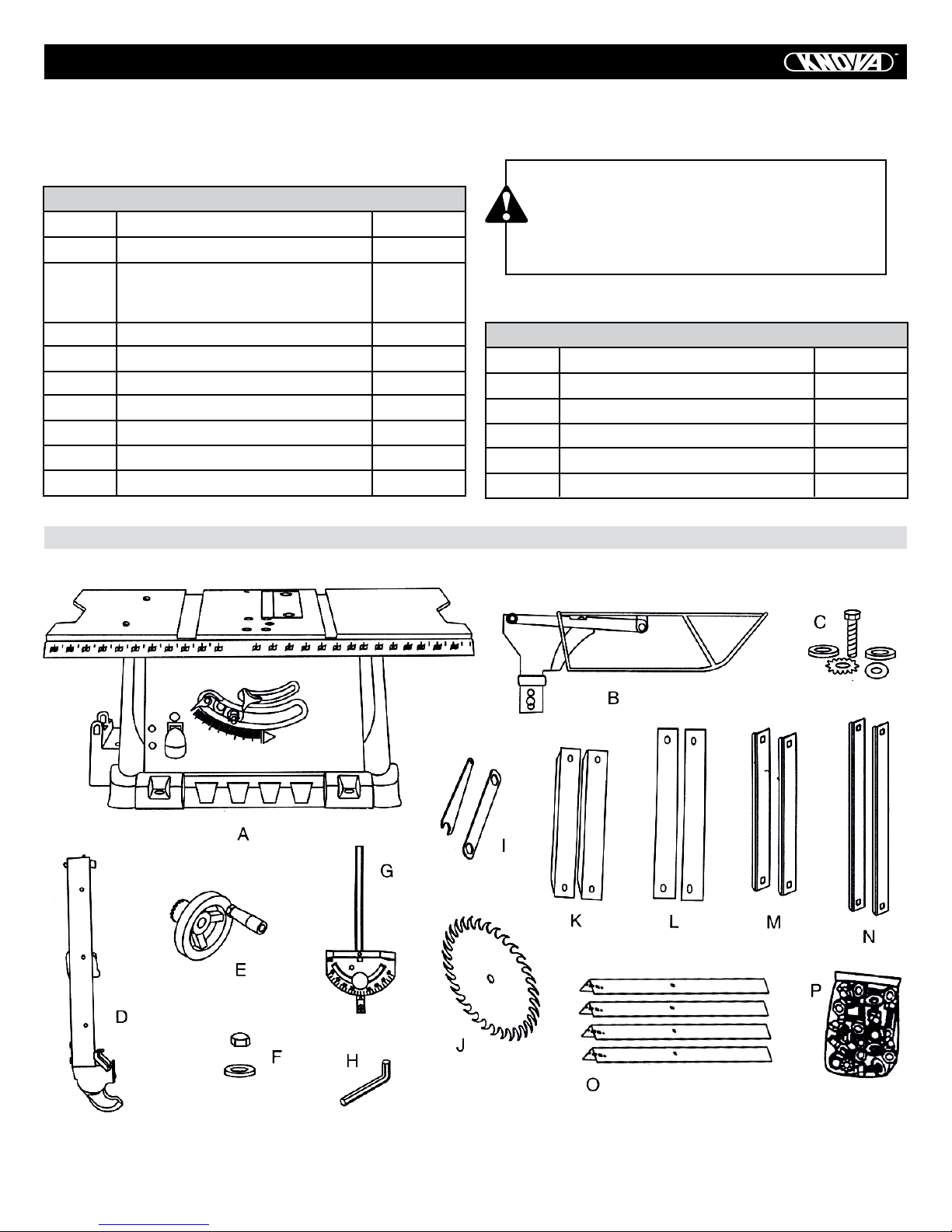
CARTON CONTENTS
UNPACKING AND CHECKING CONTENTS
Separate all parts from packing material. Check each part with the illustration and the list of carton contents (see Pages 6 and
7). Make certain you have all the required parts before discarding any packing material.
TABLE OF PARTS
ITEM DESCRIPTION QUANTITY
A Table Saw Assembly 1
B Blade Guard and Splitter 1
C Splitter Bolt, Flat Washer, Star
Washer, Spring Washer & Oval
Washer 1 each
D Rip Fence 1
E Hand Wheel Assembly 1
F Flat washer & Dome Nut 1
G Miter Gauge Assembly 1
H Hex Key 1
I Blade Wrenches 2
J Saw Blade 1
CARTON CONTENTS
CAUTION
To avoid the risk of personal injury:
• If any parts are missing, do not attempt to
assemble the saw, plug in the power cord or
turn the switch ON until the missing parts are
obtained and correctly installed.
STAND CONTENTS
ITEM DESCRIPTION QUANTITY
K K Top Short Leg Bracket 2
L Top Long Leg Bracket 2
M Bottom Short Support Bracket 2
N Bottom Long Support Bracket 2
O Leg 4
P Stand Parts Hardware Bag 1
5
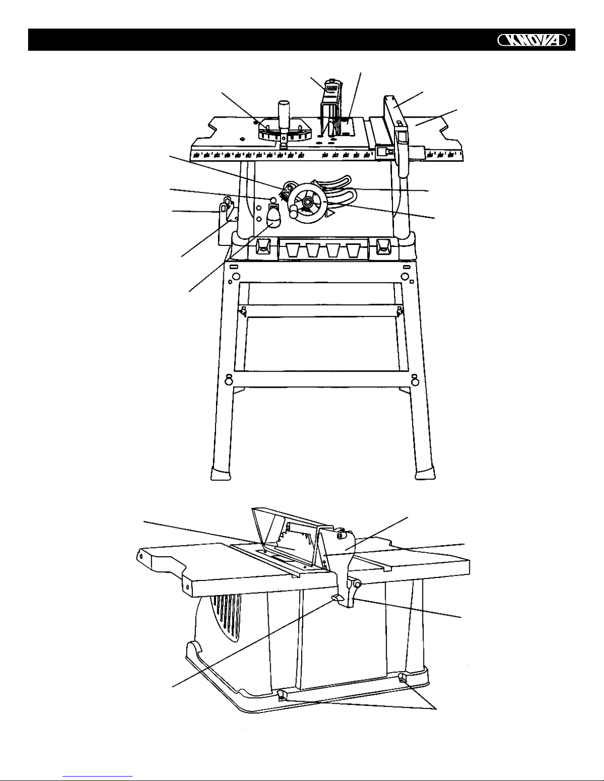
KNOW YOUR TABLE SAW
Blade Tilt Pointer & Scale
Overload Reset Switch
Miter Gauge Storage
Rip Fence Storage
ON/OFF Switch with Key
Miter Gauge
Blade Guard
Table Insert
Rip Fence
Table
Blade Bevel Lock Knob
Blade Elevation/Tilting
Handwheel
Blade
Splitter Bracket
Lock Knob
Splitter
Anti-kickback Pawls
Splitter Bracket
Mounting Holes
6
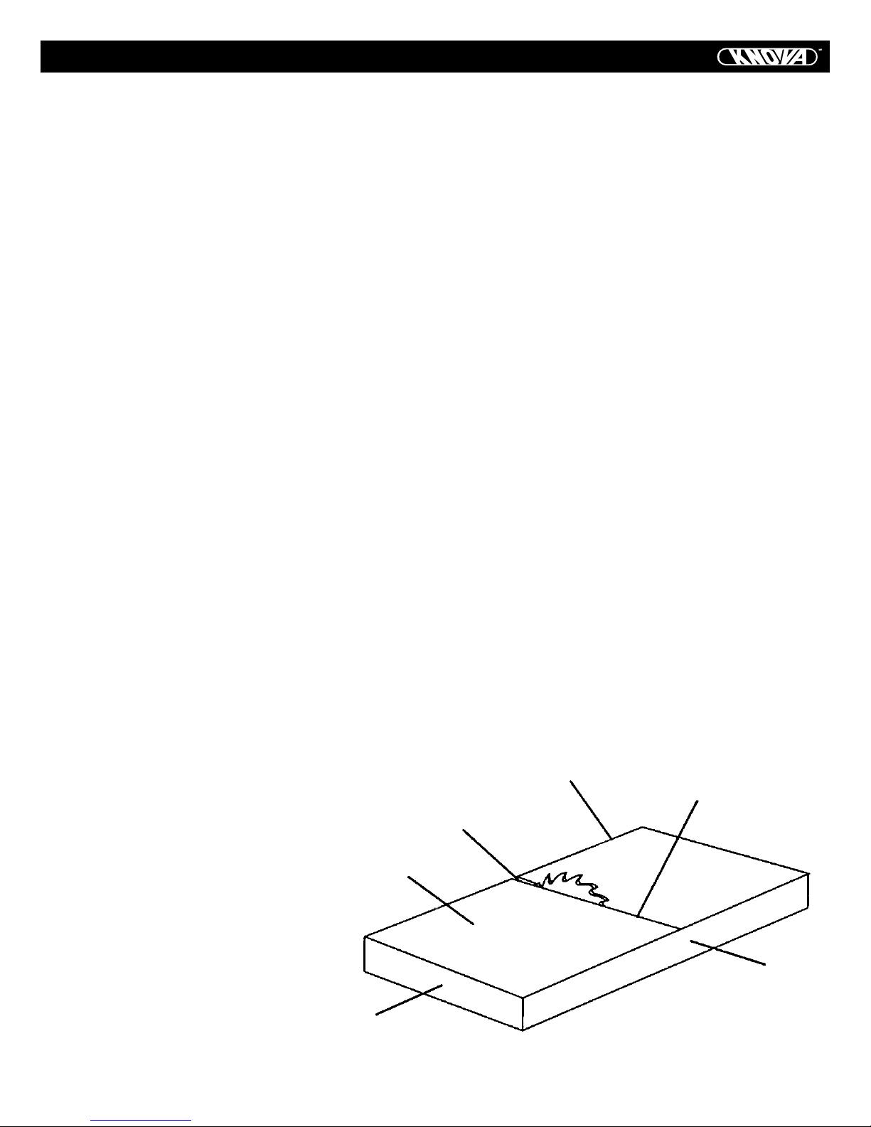
GLOSSARY OF TERMS
ANTI-KICKBACK PAWLS – Prevents the workpiece from being kicked upward or back toward the front of the table saw by
the spinning blade.
ARBOR – The shaft on which the blade or dado is mounted.
BEVEL CUT – An angle cut made through the face of the workpiece.
BLADE BEVEL SCALE – Measures the angle the blade is tilted
when set for a bevel cut.
BLADE ELEVATION/TILTING HANDWHEEL – Raises and lowers the blade. Tilts the blade to any angle between 0o and 45o
for bevel cuts.
BLADE GUARD – Clear plastic cover that is positioned over
the blade while cutting.
COMPOUND CUT – A simultaneous bevel and miter cut.
CROSSCUT – A cut made across the width of the workpiece.
DADO – Special cutting blades that are used to cut grooves
in a workpiece.
DUST PORT – Hole in back of saw base for attachment of
vacuum hose.
FREEHAND – Performing a cut without using a rip fence, miter gauge, hold down or other proper device to prevent the
workpiece from twisting during the cutting operation.
GUM – A sticky sap from wood products.
HEEL – Misalignment of the blade.
JAM NUT – Nut used to lock another nut in place on a threaded rod or bolt.
KERF – The amount of material removed by the blade cut.
MITER CUT – An angle cut made across the width of the workpiece.
MITER GAUGE – A guide used for crosscutting operations
that slides in the table top channels (grooves) located on either side of the blade. It helps make accurate straight or angle
crosscuts.
OVERLOAD RESET SWITCH – Resets the thermocouple and
provides a way to restart the saw motor if it overloads or overheats.
PUSH STICK – Accessory that is used to push the workpiece
through the cut to avoid placing your hands close to the
blade.
RESIN – A sticky sap that has hardened.
REVOLUTIONS PER MINUTE (RPM) – The number of turns
completed by a spinning object in one minute.
RIP FENCE – A guide used for rip cutting that clamps to the
table top. It allows the workpiece to cut straight.
RIPPING – Cutting with the grain of solid wood or along the
length of the workpiece.
SAW BLADE PATH – The area of the workpiece or table top
directly in line with the travel of the blade, or the part of the
workpiece that will be cut.
SET – The distance between two saw blade tips, bent outward
in opposite directions to each other. The farther apart the tips
are, the greater the set.
SPLITTER – Keeps the workpiece split apart after being cut to
prevent binding on the blade and workpiece.
TABLE INSERT – Metal insert that is removed from the table
to install/remove blades. It is also removed for dado cutting.
When dado cutting, a dado insert plate must be used.
THROUGH-SAWING – Making a cut completely through the
length or width of a workpiece.
WORKPIECE – Material to be cut.
Leading Edge
Saw Blade Path
Kerf
Surface
Trailing Edge
Workpiece
7
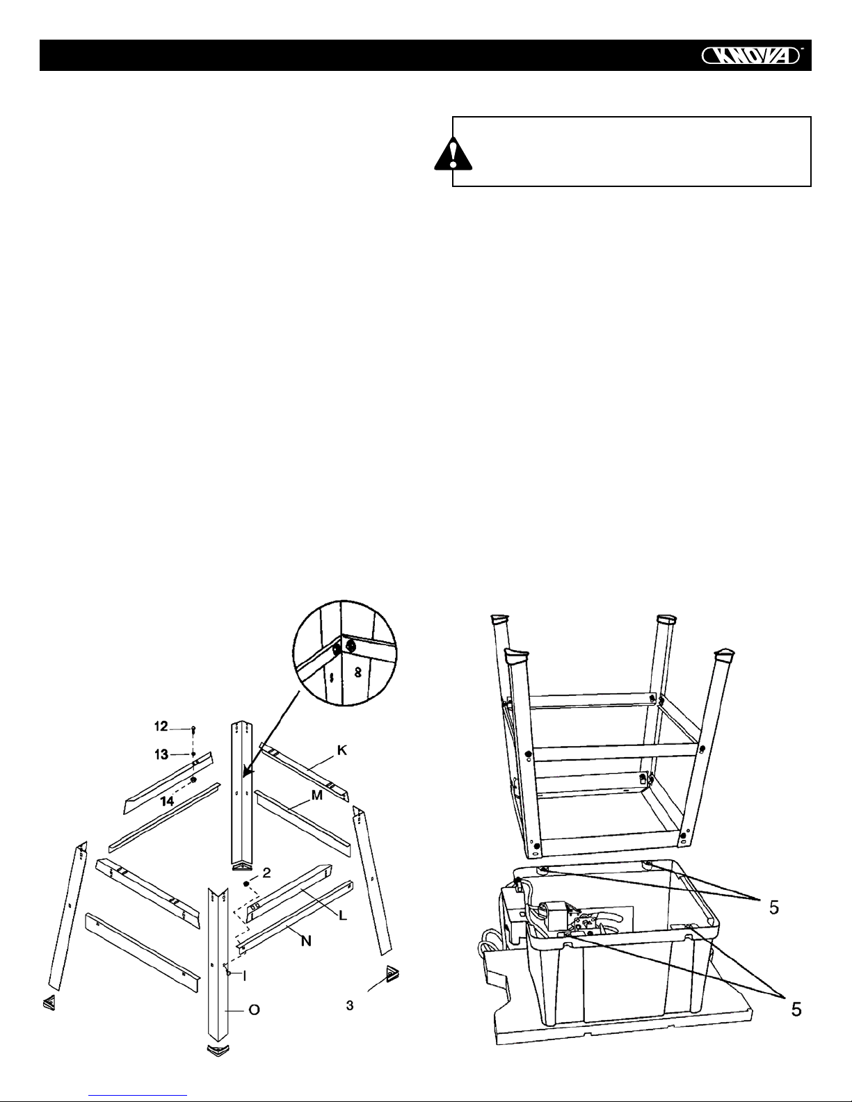
ASSEMBLY
Estimated Assembly Time: 40 – 60 minutes
ASSEMBLE STAND (FIG. 1)
1. Unpack all parts and group by type and size. Refer to the
Carton Contents.
2. Attach one long top support (L) to top of leg (O) using one
bolt (1) and nut (2).
NOTE: Do not tighten bolts until stand is properly aligned (see
step # 8 before tightening).
3. Attach other end of long top support to top of another leg
using one bolt and nut.
4. Attach one long bottom support (N) to center of each leg
using bolt (1) and nut (2). This completes the front frame section.
5. Assemble rear frame section in exactly the same manner.
6. Join front and rear frame assemblies using two short top
supports (K) and two short bottom supports (M), bolts and
nuts.
7. Insert foot pad (3) onto bottom of leg. Repeat for each leg.
8. Place stand on level surface and adjust so all legs are contacting the floor and are at similar angles to the floor. Tighten
all bolts.
NOTE: Stand should not rock after all bolts are tightened.
MOUNT ASSEMBLE TABLE SAW TO STAND (FIG. 1, 2)
CAUTION
Do not operate this machine directly on the floor
without using the stand. This is a very dangerous position.
1. Place cardboard or an old blanket on the floor to protect the
saw table surface.
2. Place the saw upside down on the protective material (Fig. 2).
3. Position the stand upside down on the saw base.
NOTE: Make sure front of stand (identified with label) and
front of saw are facing the same direction.
4. Line up the four holes (5) in saw base and stand.
5. Fasten saw to stand using four bolts (12), washers (13) and
nuts (14).
NOTE: Place washer on each bolt before inserting into saw
base and through the support. Nut must be positioned against
the bracket (see Fig. 1).
6. Tighten all four nuts.
NOTE: DO NOT OVERTIGHTEN NUTS HOLDING SAW TO
STAND. THIS WILL DAMAGE THE SAW BASE.
7. Carefully set the saw in its upright position on a clean
level surface.
Fig. 1
Fig. 2
8
ASSEMBLY
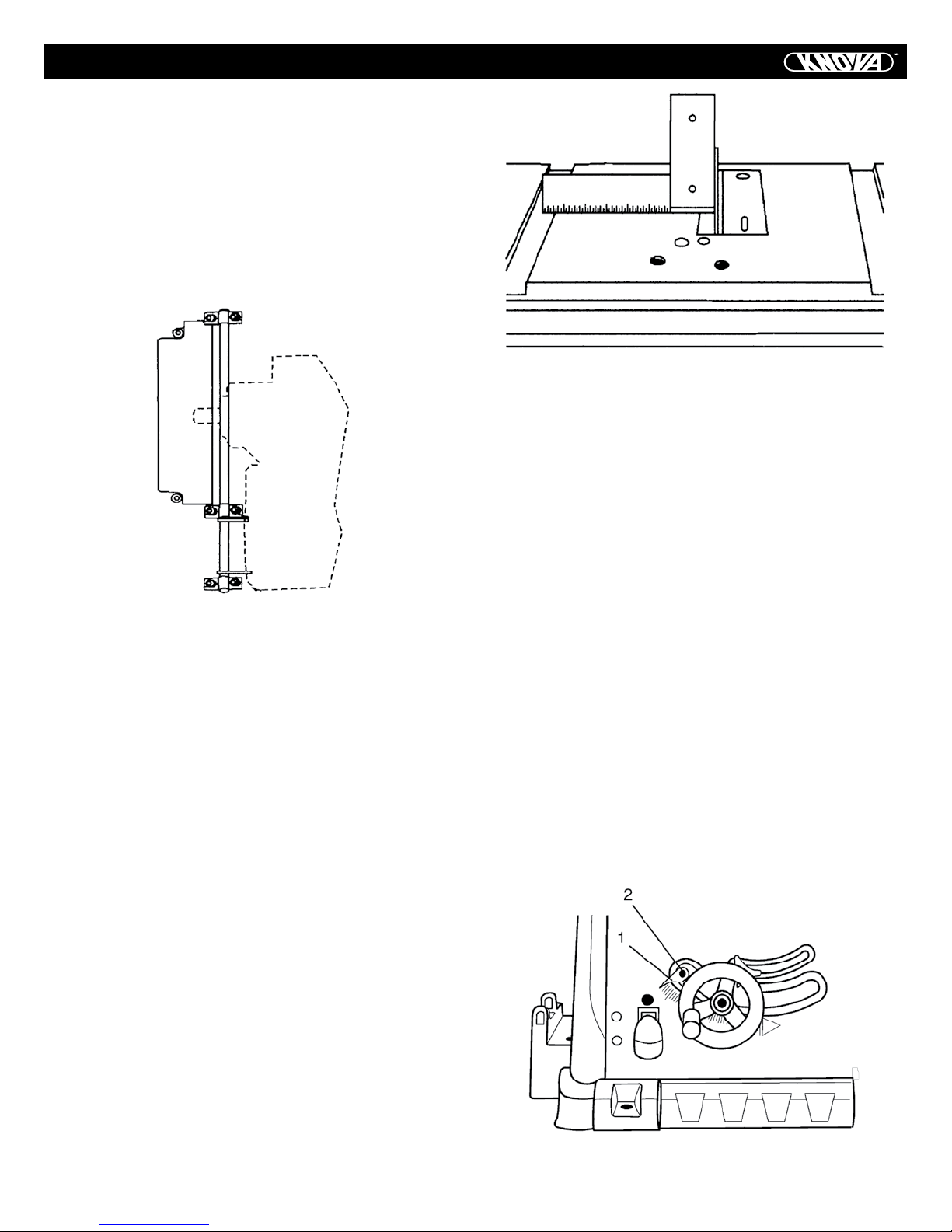
MOUNTING SAW TO ALTERNATIVE BASE (FIG. 3)
1. This saw MUST be properly secured to a sturdy workbench,
stand or cabinet. Use the four 3/8 in. holes already provided
in the saw base. The front two holes (1) are shown in Fig. 3.
There are two additional holes in the rear of the saw base.
Fig. 3
WHEN NOT USING SAW ON THE STAND, PROVIDE A SAWDUST CUTOUT IN THE WORK SURFACE.
CAUTION
Do not operate this Table Saw on a flat surface without first cutting a hole 12 in. square under the saw to
allow sawdust to fall through and be removed. Failure to provide this sawdust removal hole will cause
sawdust to build up around the motor which could
result in a fire hazard or cause damage to the motor.
Unplug unit from power source before attempting any
sawdust removal.
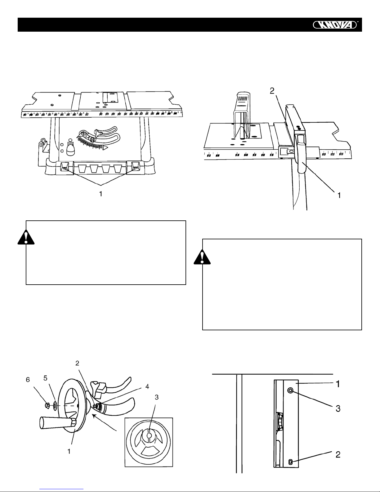
ASSEMBLE BLADE ELEVATION/TILTING
HANDWHEEL (FIG. 4)
1. Attach blade elevation and tilting handwheel (1) to the
height regulating bolt (2). Make sure the slot (3) in the handwheel hub is engaged with the roll pin (4) in the height regulating bolt.
2. Fasten handwheel to height regulating bolt with flat washer
(5) and dome nut (6).
RIP FENCE (FIG. 5)
1. Lift up on the rip fence handle (1) so the rear fence clamp
(2) is fully extended.
2. Place the rip fence on the saw table and push down on the
rip fence handle (1) to lock.
Fig. 5
INSTALLING AND CHANGING THE BLADE (FIG. 6, 7, 8)
CAUTION
• To avoid injury from an accidental start, make sure
the switch is in the OFF position and the plug is
not connected to the power source outlet.
• To avoid serious injury, the rear of the table insert
must be level with the table. A rubber adjusting
spacer is provided under the rear of the insert for
this purpose. If the rear of the table insert is not
level with the rear of the table, adjust the screw (3)
until it is level with the table. To raise the insert,
turn the screw counterclockwise. To lower the
insert, turn the screw clockwise.
NOTE: The front of the insert is stationary and non-adjustable.
1. Remove the table insert (1) by unscrewing the two screws
(2, 3). Be careful not to lose the rubber washer that is on the
back screw (3) beneath the table insert. (Fig. 6)
Fig. 4
Fig. 6
9
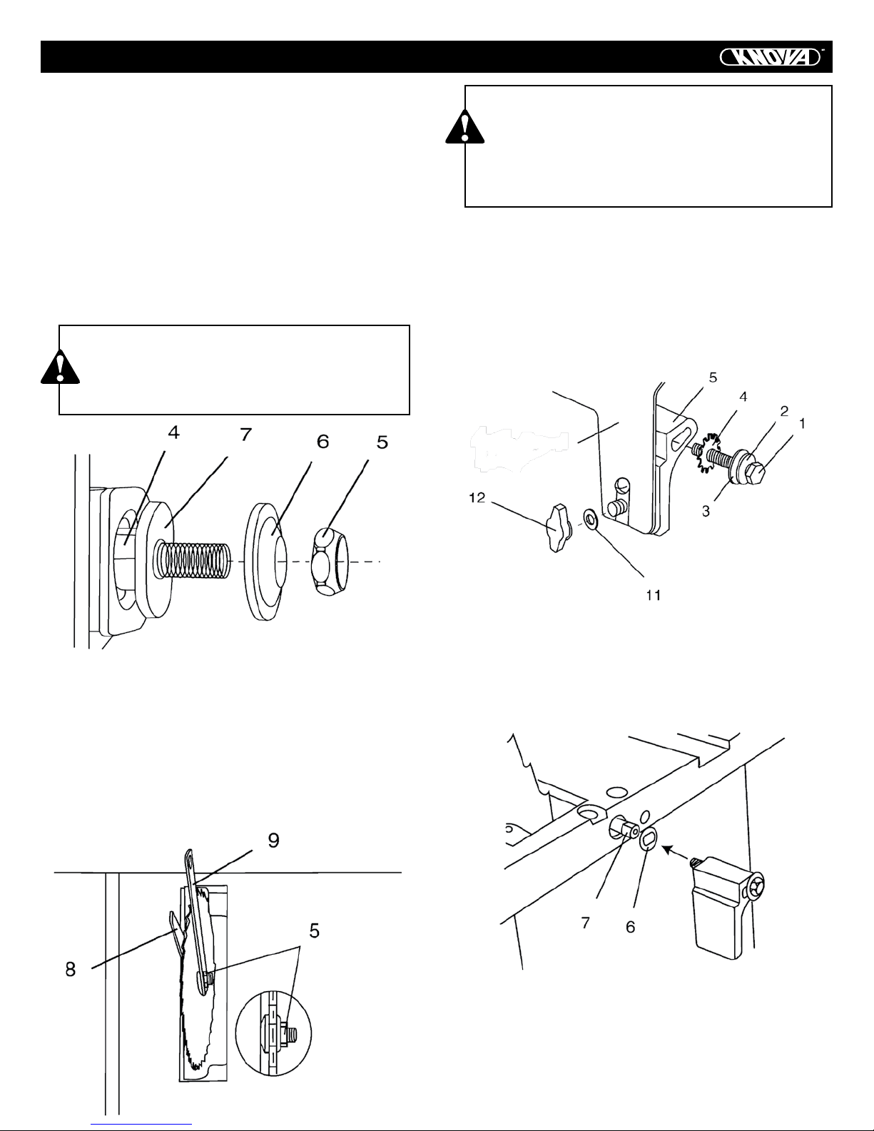
ASSEMBLY
2. Raise the blade arbor (4) to the maximum height by turning
the blade handwheel counterclockwise. (Fig.7)
3. Place the open-end wrench jaws (8) on the flats of the saw arbor to keep the arbor from turning and place the box-end wrench
(9) on the arbor nut (5), and turn counterclockwise. (Fig.8)
4. Remove the arbor nut (5) and flange (6). (Fig.7)
5. Install the saw blade onto the arbor with the blade teeth
pointing toward the front of the saw.
6. Install the flange (6) against the blade and thread the arbor
nut (5) as far as possible by hand. Ensure that the blade is
flush against the inner side of the blade flange. (Fig.7)
NOTE: Make sure all parts are clean before assembling.
CAUTION
To avoid possible injury and damage to the workpiece, install the blade with the teeth pointing toward the front of table in the direction of the rotation arrow on the blade guard.
CAUTION
To avoid injury from a thrown workpiece, blade parts
or blade contact, never operate saw without the
proper insert in place. Use the original table insert
when performing all through-sawing operations. Use
a dado table insert (not included) when performing
all non-through-sawing operations.
BLADE GUARD ASSEMBLY (FIG. 9, 10, 11)
1. Set the blade to maximum height and the tilt to zero degrees on the bevel scale with the handwheel. Lock the blade
bevel lock knob.
2. Place the spring washer (2), flat washer (3), external tooth
lock washer (4) onto the blade guard mounting bolt (1) (Fig. 9).
3. Insert bolt and washer assembly through splitter bracket (5).
Blade Guard
Splitter
Fig. 7
7. To tighten the arbor nut (5), place the open-end wrench
jaws (8) on the flats of the saw arbor to keep the arbor from
turning. (Fig. 8)
8. Place the box-end wrench (9) on the arbor nut (5), and turn
clockwise (to the rear of the saw table). (Fig.8)
9. Replace the blade insert in the table recess. Insert the
screws through the front and rear holes, remembering the
rubber spacer is under the rear of the insert. Tighten the rear
screw until insert is level or slightly above the table surface.
Fig. 9
4. Place the oval washer (6) on the pivot rod (7) (Fig. 10).
5. Install the blade guard splitter and bracket assembly into
the rear of the saw table. Thread the bolt (1) into the internally
threaded pivot rod until snug.
NOTE: The blade guard and splitter is removed from the illustration for clarity.
Fig. 10
Fig. 8
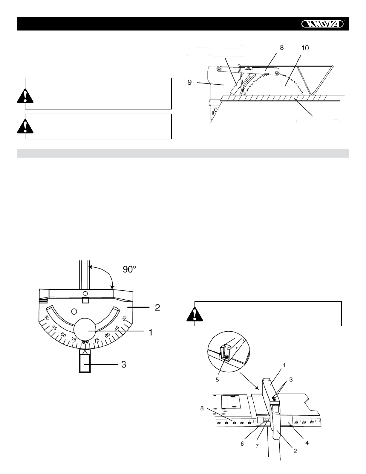
6. Lift blade guard arm (8) up and using a straight edge, align
the blade guard splitter (9) with the saw blade (10) (Fig. 11).
7. Shift the splitter bracket assembly right or left until parallel
alignment to the blade is achieved.
10
ASSEMBLY
8. When the splitter is properly aligned with the saw blade,
tighten the bolt securely.
NOTE: The splitter bracket must always be correctly aligned
so the cut workpiece will pass on either side without binding
or twisting.
CAUTION
See Fig. 9, flat washer (11) must be under knob
(12). NOTE: Be sure knob is securely tightened
and periodically check tightness.
Anti-Kickback Pawl
CAUTION
Improper splitter alignment can cause kickback
and serious injury.
ADJUSTMENTS
MITER GAUGE ADJUSTMENT (FIG. 12)
1. Loosen the lock handle (1) to allow miter body (2) to rotate
freely (Fig. 12). Position the miter body at 90° so the positive
detent secures its position. Tighten the lock handle to hold the
miter body in position.
2. If the pointer (3) requires adjustment, loosen the two screws
under the pointer with a hex key. Adjust the pointer to 90° on
the scale then firmly tighten both adjusting screws.
3. To change angles on miter gauge, loosen the lock handle
(1) and rotate the miter body to desired angle as indicated by
the scale. Secure in position by tightening the lock handle.
Straight edge
Fig. 11
4. If adjustment is needed to make the fence parallel to the
groove, do the following:
• Loosen the two screws (3) and lift up on the handle (2).
• Hold the fence bracket (4) firmly against the front of the saw
table. Move the far end of the fence until it is parallel with the
miter gauge groove.
• Push the handle to lock and tighten both screws.
5. If fence is loose when the handle is in the locked (downward) position, do the following:
• Lift the handle (2) and turn the adjusting nut (5) clockwise
until the rear clamp is snug. Do not turn the adjusting screw
more than 1/4 turn at a time.
• Overtightening the adjusting screw will bend the rear clamping lever and will cause the fence to come out of alignment.
Fig. 12
RIP FENCE ADJUSTMENT (FIG. 13)
1. The fence (1) is moved by lifting up on the handle (2) and
sliding the fence to the desired location. Pushing down on the
handle locks the fence in position.
2. Position the fence on the right side of the table and along
the edge of the miter gauge groove.
3. Lock the fence handle. The fence should be parallel with
the miter gauge groove.
CAUTION
Failure to properly align fence can cause kickback
and serious injury.
Fig. 13
11

ADJUSTMENTS
RIP FENCE INDICATOR ADJUSTMENT (FIG. 13)
1. The rip fence indicator (6) points to the measurement scale
(8). The scale shows the distance from the side of the fence
closest to the blade.
2. Measure the actual distance with a rule. If there is a difference between the measurement and the indicator, adjust the
indicator (6).
3. Loosen the screw (7) and slide the indicator to the correct
measurement on the scale. Tighten the screw and re-measure
with the rule.
BLADE TILTING MECHANISM
The saw blade can be tilted two different ways.
RAPID BLADE TILTING (FIG. 14)
1. Loosen blade bevel lock knob (2).
2. Slide the entire handwheel assembly (1) to desired location.
3. Tighten locking knob (2). Ensure locking knob is fully tightened before attempting a cut.
MICRO-ADJUSTMENT BLADE TILTING (FIG. 14)
1. Loosen blade bevel lock knob (2).
2. Push handwheel (1) IN to engage the handwheel gears with
the segment gear on the table saw base.
3. While holding handwheel IN, turn the handwheel to tilt the
blade to the desired angle.
4. Tighten lock knob to secure bevel angle.
NOTE: Changing the blade angle can be done independently
of changing blade height.
CAUTION
Blade bevel lock knob (2) must be firmly tightened
and locked during all cutting operations.
It is not necessary to loosen blade tilting locking knob (2)
when raising or lowering the saw blade.
BLADE PARALLEL TO THE MITER GAUGE GROOVE (FIG. 15, 16)
This adjustment was made at the factory, but it should be re-
checked and adjusted if necessary.
CAUTION
Always disconnect plug from the power source before making any adjustments.
• This adjustment must be correct to help prevent
kickback injuries and ensure accurate cuts.
1. Remove the safety switch key and unplug the saw.
2. Remove the blade guard for this procedure but reinstall and
realign after adjustment.
3. Raise the blade to the highest position and set at the 0°
angle (90° straight up).
4. Select and mark, with a felt tip maker, a blade tooth having
a “right set” and rotate the blade so the marked tooth is 1/2
in. above the table at the front of the saw.
5. Place the combination square base (1) into the right side
miter gauge groove (2).
6. Adjust the rule so it touches the front marked tooth and lock
ruler so it holds its position in the square assembly.
7. Rotate the blade bringing the marked tooth to the rear and
about 1/2 in. above the table.
8. Carefully slide the combination square to the rear until the
ruler touches the marked tooth.
9. If the ruler touches the marked tooth at the front and rear
position indicating the same measurement, no adjustment is
needed at this time. If not, perform adjustment procedure described in next section.
BLADE HEIGHT ADJUSTMENT (FIG. 14)
To raise the saw blade, turn handwheel (1) COUNTERCLOCK-
WISE. To lower the blade, turn the handwheel CLOCKWISE.
Fig. 14
Fig. 15
ADDITIONAL BLADE ADJUSTMENTS (FIG. 16) TOOLS REQUIRED (NOT SUPPLIED)
• 10 mm open end or 10 mm combination wrench
• 4 mm hex key • Framing square
• Medium size slotted screwdriver
12
ADJUSTMENTS
ADJUSTMENT PROCEDURE
1. Turn saw switch OFF and remove plug from the power
source.
2. Remove blade guard and splitter assembly, miter gauge and
rip fence.
3. Using the 10 mm hex wrench, slightly loosen the two middle
blade alignment rod strap bolts (1) and two rear blade alignment rod strap bolts (2) located on the underside of the saw
table (see Fig. 16).
Fig. 16
4. While standing at the rear of the saw, use a medium size
slotted screwdriver and gently pry the rear of the blade alignment rod to the LEFT or RIGHT. Using the framing square,
simultaneously measure the distance at the front and rear of
the blade to an edge of a miter slot. When the distances are
within 1/64 in. or closer, tighten both rear blade alignment rod
strap bolts (2) while holding the rod firmly in place.
NOTE:
The blade alignment rod will only move slightly.
5. If alignment is not achieved by rear adjustment, loosen the
two front blade alignment rod strap bolts (3).
6. While standing at the front of the saw, use a medium size
slotted screwdriver and gently pry the front of the blade alignment rod to the RIGHT or LEFT. Simultaneously measure the
distance at the front and rear of the blade to an edge of a miter
slot. When the distances are with in 1/64 in. or closer, tighten
both front blade alignment rod strap bolts (3) while holding
the rod firmly in place. NOTE: The blade alignment rod will
only move slightly.
Fig. 17
0° BEVEL STOP (FIG. 17)
1. Raise the blade to maximum height by rotating the handwheel counterclockwise.
2. Loosen bevel angle lock knob.
3. Tilt the blade to 0° bevel.
4. Using a square (1), verify blade is 90° to the table top.
5. If blade is not 90° to the table, back off the adjustment
screw (2).
6. Loosen bevel lock knob and square blade 90° to the table.
7. Once blade is at 90° to the table top, lock bevel angle
locking knob.
8. Carefully tighten adjusting screw (2) until it touches
the bevel stop. DO NOT OVERTIGHTEN.
9. Recheck to ensure blade is still aligned at 90°.
BEVEL POINTER ADJUSTMENT (FIG. 18)
When you have achieved a 90° angle of the blade to the table
top as described in section above, the angle pointer (1) may
require adjustment. If so, follow proceeding steps:
1. Loosen pointer screw (2) and move the pointer so it is
aligned with 0° on the bevel scale.
2. Retighten the pointer screw.
7. Tighten both middle blade alignment rod strap bolts (1).
NOTE: Recheck to make sure all six bolts are properly tightened and that the distance from the front and rear of the blade
to the miter gauge groove are within 1/64th of an inch from
one another.
8. Reinstall blade guard and splitter assembly and adjust the
alignment with the blade as outlined earlier in the operator’s
manual.
Fig. 18
13

ADJUSTMENTS
45° BEVEL STOP (FIG. 19)
1. Raise the blade to maximum height by rotating the handwheel counterclockwise.
2. Loosen bevel angle lock knob.
3. Tilt the blade to 45° bevel.
4. Using a square (1), verify blade is 45° to the table top.
5. If blade is not 45° to the table, back off the adjustment
screw (2).
6. Loosen bevel lock knob and square blade 45° to the table.
7. Once blade is at 45° to the table top, lock bevel angle locking knob.
OPERATION
BASIC SAW OPERATIONS
ON/OFF SWITCH (FIG. 20)
The on/off switch (1) is located on the front panel of the saw
base. To turn the saw ON, move the switch to the up position.
To turn the saw OFF, move the switch to the down position.
LOCKING SWITCH IN OFF POSITION (FIG. 20)
When the saw is not in use, the switch should be locked in the
OFF position. To lock the switch in the OFF position, pull out
the safety key (2) from the center of the switch. The saw will
not start with the key removed. However, if the key is removed
while the switch is in the ON position, it can be turned off
ONCE. The saw will not restart until the key has been reinserted into the switch and the switch is turned on.
OVERLOAD PROTECTION (FIG. 20)
DANGER
To avoid injury, the ON/OFF switch should be in the
OFF position and the plug removed from the power
source while the motor cool down takes place. This
will prevent accidental starting when the reset button
is pushed. Overheating may be caused by misaligned
parts, a dull blade or an undersized extention cord. Inspect the saw for proper setup before using it again.
This saw is equipped with a thermal overload reset
switch. If the motor shuts off or fails to start due to
overloading or low voltage, turn the switch to OFF
position and let the motor cool down and remove all
cutting materials from the saw. After the motor has
cooled down, push the reset button (3) to reset the
overload device. The saw should now start when the
switch is returned to the ON position.
Fig. 20
8. Carefully tighten adjusting screw (2) until it touches the
bevel stop. DO NOT OVERTIGHTEN.
9. Recheck to ensure blade is still aligned at 45°.
Fig. 19
CUTTING OPERATIONS
There are two basic types of cuts: ripping and crosscutting.
Ripping is cutting along the length and the grain of the workpiece. Crosscutting is cutting either across the width or across
the grain of the workpiece. Neither ripping nor crosscutting
may be done safely freehand. Ripping requires the use of the
rip fence, and crosscutting requires the miter gauge.
CAUTION
Before using the saw each and every time, check the
following:
1. Blade is tight on the arbor.
2. Bevel angle lock knob is tight.
3. If ripping, fence knob is tight and fence is parallel
to the miter gauge grooves.
4. Blade guard is in place tightly and working
properly.
5. Safety glasses are being worn.
The failure to adhere to these common safety rules, and those
printed in the front of this manual, greatly increases the likelihood of injury.
RIPPING (FIG. 21, 22)
CAUTION
To prevent serious injury:
• Never use the miter gauge when ripping.
• Never use more than one rip fence during a
single cut.
• Do not allow familiarity or frequent use of your
table saw to cause careless mistakes. Remember
that even a careless fraction of a second is enough
to cause a severe injury.
• Keep both hands away from the blade and path
of the blade.
• When ripping, the workpiece must have a straight
edge against the fence and must not be warped,
twisted, or bowed.
14

OPERATION
1. Remove the miter gauge. Secure the rip fence to the table.
2. Raise the blade so it is about 1/8 in. higher than the top of
the workpiece.
3. Place the workpiece flat on the table and against the fence.
Keep the workpiece about 1 in. away from the blade.
4. Turn the saw ON and wait for the blade to come up to
speed.
5. Slowly feed the workpiece into the blade by pushing forward only on the workpiece section (1) that will pass between
the blade and the fence. (Fig. 21)
CAUTION
AVOID KICKBACK by pushing forward on the section of the workpiece that passes between the blade
and the fence.
Fig. 21
6. Keep your thumbs off the table top. When both of your
thumbs touch the front edge of the table (2), finish the cut with
a push stick. Make a push stick using the pattern on page 25.
7. A push stick (3) should always be used. (Fig. 22)
8. Continue pushing the workpiece with the push stick (3) until it passes the blade guard and clears the rear of the table.
9. Never pull the piece back when the blade is turning. Turn
the switch OFF. When the blade completely stops, raise the
anti-kickback pawls on each side of the splitter and slide the
workpiece out.
CROSSCUTTING (FIG. 23)
CAUTION
To prevent serious injury:
• Do not allow familiarity or frequent use of your
table saw to cause careless mistakes. Remember
that even a careless fraction of a second is
enough to cause a severe injury.
• Keep both hands away from the blade and the
path of the blade.
• Never attempt to pull the workpiece backwards
during a cutting operation. This will cause
kickback and serious injury to the user can occur.
1. Remove the rip fence and place the miter gauge in a miter
gauge groove on the table.
2. Adjust the blade height so it is 1/8 in. higher than the top
of the workpiece.
3. Hold the workpiece firmly against the miter gauge with
the blade path in line with the desired cut location. Move the
workpiece to 1in. distance from the blade.
4. Start the saw and wait for the blade (1) to come up to full
speed. Never stand directly inline of the saw blade path, always stand to the side of the blade that
you are cutting on.
5. Keep the workpiece (2) against the face of the miter gauge
(3) and flat against the table. Then slowlypush the workpiece
through the blade.
6. Do not try to pull the workpiece back with the blade turning. Turn the switch OFF, and carefully slide the workpiece out
when the blade is completely stopped.
CAUTION
Always position the larger surface of the workpiece on the table when crosscutting and/or bevel
crosscutting to avoid instability.
Fig. 22
Fig. 23
15
 Loading...