

Page 1
SP66 IN-W ALL SPEAKER
OWNERS MANUAL
Congratulations and thank you for choosing Knöll inwall speakers! To
assure correct installation and to realize the full potential of these new
speakers, please read and follow these instructions carefully. If you
have questions or comments, please don't hesitate to call or write your
authorized Knöll dealer. Your dealer has the experience needed to
pinpoint any problems that may exist and has easy access to technical
information from the Knöll factory.
Speaker Placement
Knöll SP66 speakers are designed to work within almost any interior
decorating scheme where inwall or flush mounting is possible. Ideally
SP66 speakers are ceiling mounted 2-3 meters (6'-10') apart, away from
corners directly over the listening area. This ideal placement gives the
best stereo imaging. Position SP66 speakers as symmetrically as
possible. SP66 speakers can be ceiling or wall mounted.
Installation T ips
1. Follow all electrical and building code requirements in your area.
2. A minimum mounting depth of 3-1/4" (8.25cm) measured from the
face of the wall or ceiling is needed in order to fit properly. SP66
speakers can be placed right next to studs or other wall interior items
but avoid near proximity to pipes, machinery and high amperage
wiring.
3. The mount brackets provided with SP66 speakers can accommodate
sheet rock or wall board thicknesses of 1/2" to 1-3/8". Spacers or
longer screws can be used on thinner and thicker surfaces.
4. Avoid mounting speakers closer than 0.5m (20") from a video
monitor or TV screen. If any video or TV screen distortion is detected,
the video monitor or TV should be moved farther away from the
speaker.
5. It is not necessary to install SP66 speakers in a special box unless
required to do so by local electrical or fire regulations.
6. Adding insulation such as 10cm (4") rock wool behind the SP66
generally improves sound quality.
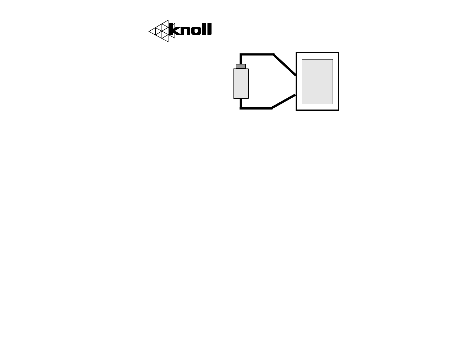
Fig 1: SPEAKER POLARITY VERIFICATION
7. Speaker wire should be
+
1.5VDC
BATTERY
+
SP66
-
-
correct amplifier loading. Avoid series wiring SP66 speakers with any
other speaker type.
9. Always take care to connect the speaker wire runs in phase. An easy
method verify polarity follows. Connect a 1.5V battery across the speaker
wire at the amplifier location (see fig 1) Have someone observe if the
SP65 cone moves in or out. If the cone goes out (toward the observer) the
+ wire is now connected to the + terminal of the battery and that wire
should be connected to the + terminal of the amplifier. Other speaker(s)
should be tested and connected in a similar manner.
minimum 16 gauge (ideally
fire code rated, low oxygen
wire. Runs longer than 10m
(30') should be 14 or 12
gauge.
8. Parallel or series wiring is
generally acceptable for
SP66 speakers to obtain
Installation: Existing Construction
1. Use a stud locator device or other means to determine suitable sized
cavity in the wall or ceiling for the SP66.
2. When ceiling mounting try to make the locations as symmetrical as
possible. When wall mounting carefully measure the distance from the
floor to the speaker center so both speakers are exactly the same distance
from the floor. Draw a rectangular hole 7-1/2"x11" at the correct
location. Cut the hole out using a sheet rock saw, keyhole saw or other
suitable device. Place the SP66 mount bracket in the hole to verify correct
flush mount fit.
3. Run speaker wires from the amplifier to the room volume control
location (optional) then to the left and right speakers. Allow an extra 1m
(3') of wire at the speaker cutout location to make installation easier. Strip
and twist about 1/2" of insulation off wires. The wire runs should be
hidden as well as possible (ask your dealer for tips to conceal wires).
4. Remove the speaker grills.
Page 2

5. Connect the speaker wire to the SP66 speaker carefully observing
correct speaker terminal polarity.
6. Slip the bottom of the speaker down into the opening cut in the wall
or ceiling, slide the whole speaker into the wall cavity and center the
speaker in the hole. Tighten all six screws (just snug, don't over tighten).
This should allow the speaker to line up and clamp the wall board with
the speaker frame.
7. Turn the amplifier on, room volume controls up and test the speakers.
8. Snap the white (paintable) grill into the SP66 speaker bracket.
Installation: New Construction
1. Run two wires from the amplifier location to the room volume control
(optional) then to the intended speaker location. Loop an extra 1m (3')
of wire out from the ceiling or wall. ID tag the wires.
2. After wall board or sheet rock is installed, make sure the 7-3/4" x11"
speaker hole is cut out correctly then follow steps 4-8 in "Existing
Construction".
Amplifier or Receiver Operation
The amplifer or receiver should provide more power than will be
needed. Always reduce sound levels immediately if sound distortion is
present. Any amplifier, especially low powered amplifiers can damage
speakers when distorted sound (usually you will hear a harsh or unclear
sound) is being reproduced. Speaker damage caused by sound distortion
or gross overpowering is easily evident and is not covered by the
warranty.
SP66 Limited Warranty
Knöll Systems warrants SP66 speakers to be free from defects in
materials and workmanship. This warranty extends for one full year from
the date of purchase by the consumer. Any products returned freight
prepaid to Knöll Systems and found to be defective by Knöll systems
within the warranty period will be repaired or replaced at Knöll Systems
option, at no charge. Knöll Systems will not be responsible for the actual
cost of installation or removal of the product, nor for any consequential
or incidental damages. Some states do not allow the exclusion or limitation of incidental or consequential damages, so the above limitation or
exclusion may not apply to you. This warranty gives you specific legal
rights. You may have additional rights which vary from state to state.
Specifications
Speaker Type: 2-way
Woofer: 6-1/2" filled mica
Tweeter: 1" (25mm) Soft dome
Peak Power RMS: 80 watts
Power Rating RMS: 60 watts
Amplifier Power : 5-100 watts/channel
Nominal Impedance: 8 ohms
Sensitivity: 90 dB/W/m
Frequency Range: 50Hz-21kHz
Mount Depth Required: 3-1/4" (90mm)
Dimensions: 12-1/8 8-3/4"
Cut Out Dimensions: 11 x 7-1/2"
Color: Paintable white
Trim Ring Painting
The SP66 speaker baffle and grill can be painted to match any interior
decorating scheme. Ideally paints with nitrocellulose lacquer are used.
Most cold paint types are suitable as well. Primer can be used when
darker colors are required. We do not suggest painting the inner black
cavity or drivers.
Knöll Systems
tel (604) 272-4555
fax (604) 272-5595
Knoll Systems, Richmond, BC Canada
C
COPYRIGHT 1999, Knöll Systems,
In Canada:
11791 Machrina Way
Richmond, B.C. V7A 4V3
SP66
All Rights Reserved
In America:
145 Tyee Drive
Point Roberts, WA 98281
 Loading...