

Knoll Systems MR-640 Owners manual

Congratulations and thank you for choosing the Knöll
MR640 controller. The MR640 is designed to meet the
amplifier needs of custom installed multi-zone systems
where high quality sound is a specific requirement.
Key Features:
MR640
Six zone stereo controller with
individual volume control electronics
and four input source selection
INSTALLATION
MANUAL
It is very important to use a top quality
RJ45 8/8 crimper tool. We strongly
suggest using a cat 5 / RJ45 electronic
tester to verify the wire conductors.
For the latest information, see our web site www.knollsystems.com
Complies with part 15 of the FCC rules. Operation is subject to:
1. This device may not cause harmful interference
2. This device must accept any interference received
including interference that may cause undesired operation.
Version 1.1
1. Individual zone, four source selection. Each of the six
rooms can select any one of four stereo sources.
2. Individual mute, volume, bass and treble
adjustment. Each of the six stereo channels feature
adjustments for bass and treble. Individual room keypads
control volume and mute. Any keypad can turn the whole system
on or off.
3. External trigger and functions out. An 12VDC trigger
output is provided to turn other components on or off. Six
function ports are provided (connects to a Xantech 590) to turn
on and off components via IR as well as provide four IR
commands, sourced from the MR60 keypads
4. Adjustable source gain. Each source has individual gain
adjustments to level or equalize the gain of the various sources.
5. Stackable 17" chassis. The MR640 can be stacked or
placed in a 19" EIA equipment rack (requires RM640 kit).
6. Data port. For larger systems, multiple MR640's and
MVP64's can operate in tandem so all MR640's and MVP64's
turn off and on together, share infrared signals, page, connect to
door chimes, connect to external controllers, etc.
7. All on and all off. MR60 keypads turn on any source in all
rooms.
8. Volume level indication. MR60 keypads display volume
level on top three rows of buttons. FNC-MUTE level is the
lowest.
9. All room volume up and down (rooms on only) via FNC
button.
2

System layout considerations
The MR640 is the heart of a whole home music system. A MR640
is designed to work with 1-6 rooms or zones. Up to three
MR640's and/or MVP64's can be ganged together to allow up to
18 rooms or zones each individually controlling one or two pairs
of enclosure or inwall speakers. Connection is achieved via the
data port using a stereo 3.5mm jack on the rear of the MR640.
...system layout considerations continued
The MR640 includes a 12VDC trigger output to control and power
various items when the MR640 is powered up. When the MR640
goes into standby the trigger output ends. It's maximum output is
60mA.
Rooms are usually controlled by a MR60 keypad. The MR60
contains an almost all brand infrared repeater and most functions
can be controlled by the Knoll RB8 remote control. RB8
commands can easily be stored in a learning remote. The MR60 is
available with three different source layouts (all of the MR60
keypads in one system have to have the same source layout) and
three bezel colors white, almond and ivory for a total of 9 models.
The source layout and bezel colors are easy to change in the field.
Some rooms will not require a MR60 keypad and most MR640
functions can be utilized with an RB8 remote and an infrared
repeater (a MR173 IR converter is required). Up to three IR
receivers in three different rooms can be connected to a single
MR173 (see information shipped with the MR173). The MR640
includes four internal single or dual emitter connection ports, so
emitters will have to be ordered if required. The infrared pass
through is always available when the controller is turned on and in
standby or powered up.
In certain commercial applications a microphone paging override
is required. Model MR171 paging and override module takes a
balanced or unbalanced mic, (with automatic phantom power) or a
line level input and when activated overrides all inputs (even if
some or all zones are in standby) and pages at an adjustable preset
volume in all zones.
A variety of door chime, video switching, telephone paging, door
entry and front door camera modules are being developed. Check
our web site for more information.
...continued
In certain cases when several high powered amplifiers will be
controlled by the MR640, a delayed turn on sequence is required
to turn on the amplifier so a fuse will not trip or just cause a low
voltage situation in the house. The MR166 turn on sequence is
used to sequentially delay the trigger turn on to 6 trigger inputs in
1.5 second or 3 second delay sequences. The MR166 is also
buffered in case the 60mA output from the MR640 is insufficient.
An innovative IR connection system is also included to turn on and
off the various source components as well as four separate
commands. A Xantech 590-00 controller is required for this
purpose. The Xantech 590-00 is a an IR sequence generator. When
it receives commands from the MR640 it generates an IR
command or sequence of up to 10 commands. The on command is
automatically generated when the MR640 goes out of standby and
into power up. The off command is automatically generated when
the MR640 goes from power on to standby. These sequences are
generally used to turn on and off the source equipment.
To activate the four FNC commands on the MR60 keypad (only
when the system is powered up) press the MR60 keypad button
FNC then quickly press one of the four source buttons on the top of
the MR60 keypad. This will initiate a pulse at the MR640
FUNCTION output, that in turn generates an IR command that is
pumped back into the MR640 IR emitter port 1 and out to the
various emitters connected to ports 2-3-4, that will initiate the
command to the source component.
3
4
Installation
It is very important to use a top quality RJ45 8/8 crimper
tool. We strongly suggest using a cat 5 / RJ45 electronic
tester to verify the wire conductors.
Installing the MR640 should be relatively easy. With a bit of
planning, the MR640 will give trouble free service for years.
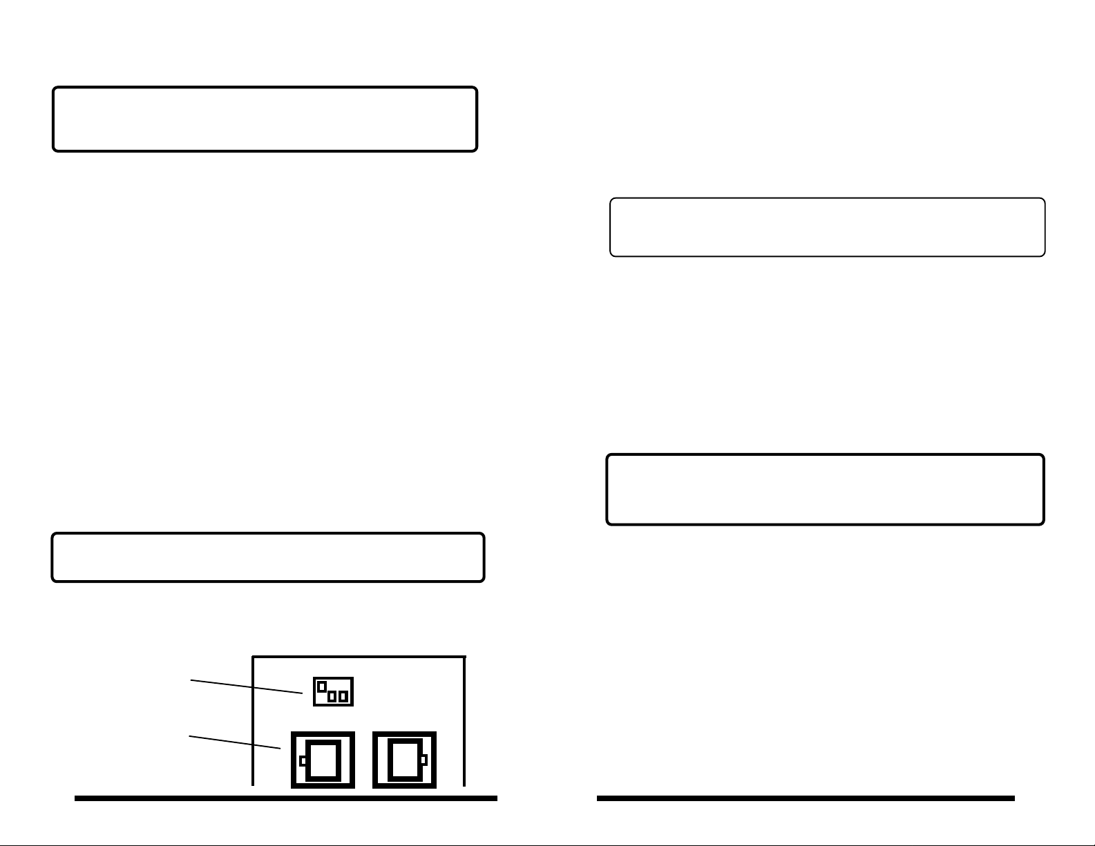
7. The rear of the MR60 is shown. Because one to three MR60's can
be connected or daisy chained to the same cat 5 wire, the keypad
position on the wire must be selected using the dip switch. The two
MR60 RJ45 connectors are in parallel. Only one dip switch slider
should be on and the other two off (#1 is shown on in this example).
The MR60 1-2-3 dip switch positions correspond to MR640 keypad
ports and speaker outputs A1-A2-A3 or B1-B2-B3.
1. When installing the MR640 in a rack we suggest mounting it on
the bottom shelf so it is not heated by power amplifiers below it.
2. Follow the amplifier manufacturers information about installing
the power amplifiers.
3. Connect the MR640 inputs to the source component outputs and
amplifiers with good quality, short as practical RCA jack cables.
Connect each channel individually.
4. In multiple MR640 and/or MVP64 installations, connect the
sources to the MR640 and MVP64 inputs using RCA Y adaptors.
5. If source D is not being used we suggest you short both left and
right jacks with a RCA shorting plug. This will make the room
speakers quieter in standby modes.
6 Install MR60 keypads (or infrared receivers) in the rooms with
the speakers. Cat 3 or cat 5 wire can be home run to the MR640 or
up to three rooms daisy chained on one wire.
***Be sure to set the dip switch on the rear of the MR60***
See the dip switch adjustment below. Connect all eight individual
wires using RJ45 connectors. Four wire conductors are needed
for each keypad (one unique, common: IR , ground and 12VDC).
MR60 Dip Switch
MR60
1 2 3 4
Adjustment
Use either RJ45
connector as they
are in parallel
***Even if the keypads are home run, the
MR60 dip switch position has to be selected***
If three keypads are daisy chained on one wire, select the MR60 dip
switch on the first MR60 to one, the second MR60 to two and the
third MR60 to three. At the rear of the MR640, the RJ45 connector
from the three MR60 keypads can be connected any corresponding
keypad Bank A or Bank B; port 1, 2 or 3. The corresponding
speaker outputs will be the same number as selected on the MR60
keypad (example: the MR60 keypad with #2 dip on and connected to
MR640 keypad bank B will control speaker outputs B2R and B2L).
After installation, if the keypads are not working properly or not
controlling at all, Check the MR60 dip switch settings, wiring
layout and crimp as well as bank connections very carefully.
8. Connect the emitters to the IR Emitter ports on the rear of the
MR640. Single or dual emitters can be used. If a Xantech 590-00 is
being installed do not connect emitters in the MR640 IR Emitter #1.
9. When connecting two or more MR640's and/or MVP64's in the
same home, connect the amps together using stereo 3.5mm plugs
(all three wires are used) to the data plug on the rear of the MR640.
The MR640's and MVP64's share power on and off data as well as
infrared signals.
10. Connect the MR640 trigger output to the amplifier triogger
inputs if the total current for the trigger is less tan 60 mA and a turn
on delay sequence is not required. If more than 60 mA or a turn on
sequence is required use the optional MR166 turn on sequencer.
5
6
 Loading...