

Knoll Systems IR-54 Owners manual
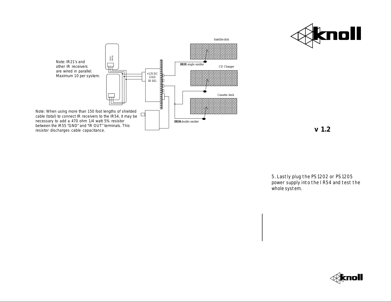
Typical IR Repeater System
9
9
9
9
9
9
9
9
0
0
0
0
0
0
0
0
9
9
9
9
9
9
9
9
IR21
+12VDC
IR SIG
GND
Note: IR21’s and
other IR receivers
are wired in parallel.
Maximum 10 per system.
Note: When using more than 150 foot lengths of shielded
cable (total) to connect IR receivers to the IR54, it may be
necessary to add a 470 ohm 1/4 watt 5% resistor
between the IR55 “GND” and “IR OUT” terminals. This
resistor discharges cable capacitance.
IR21
+12VDC
GND
IR SIG
IR54
Connection
Block
+12VDC
GND
IR SIG
PS1202
Power
Supply
234567890123456789012345678
234567890123456789012345678
234567890123456789012345678
234567890123456789012345678
234567890123456789012345678
234567890123456789012345678
234567890123456789012345678
234567890123456789012345678
IR31 single emitter
2345678901234567890123456789
2345678901234567890123456789
2345678901234567890123456789
2345678901234567890123456789
2345678901234567890123456789
2345678901234567890123456789
2345678901234567890123456789
2345678901234567890123456789
234567890123456789012345678
234567890123456789012345678
234567890123456789012345678
234567890123456789012345678
234567890123456789012345678
234567890123456789012345678
234567890123456789012345678
234567890123456789012345678
IR34 double emitter
Satellite dish
CD Changer
Cassette deck
Note: Position and attach
emitter over component
IR window
IR54
Infrared
Connection
Module
Information and
Installation Guide
v 1.2
IR54 Features
* Easy to install, easy to use!
* No maintenece or adjustments
*Connect up to 10 infrared receivers
*Connect up to 8 emitters (four IR34 double
emitters)
*Connect a PS1202 or PS1205 power supply
Specifications
Infrared carrier frequency: 30-60kHz
Power requirements: PS1202 200mA or PS1205
500mA unregulated 12VDC power supply
Dimensions: 4.1” h x 1.5” w x 1.5” deep
(104 x 38 x 38mm).
Color: White, almond ivory or black decora style
Installation Tips:
1. Follow all local electrical & building code
requirements.
2. The IR54 is usually positioned behind the
stereo components it is helping to control.
3. Connect all of the infrared receivers in parallel
to the IR54 three terminal connector as shown in
the diagram. Wires can be solid or stranded,
shielded or unshielded with a minimum of 24
gauge for runs under 200’, 22 gauge for runs
under 500’ and 20 gauge for runs up to 1000’.
Wires can be looped from IR receiver to receiver
or home run. Home runs generally offer more
reliability and future flexibility.
4. Connect the emitters by inserting their plugs
into any available IR54 emitter jack. Up to four
single emitter or double emitters (maximum eight
emitters) can be connected to a single IR54. If
more emitter connections are required, call Knoll
for amplified connection block information.
5. Lastly plug the PS1202 or PS1205
power supply into the IR54 and test the
whole system.
Warranty
Knoll Systems warrants its products sold in the USA by authorized
Knoll Systems dealers to be free from defects in materials and workmanship.
The warranty extends for two full years from the date of purchase by the
original consumer. Any products returned within the warranty period will be
repaired or replaced at Knoll Systems option, at no cost. Knoll Systems will not
be responsible for the actual cost of removal or reinstallation of the product, nor
of any incidental or consequential damages. Some states do not allow the
exclusion or limitation of incidental or consequential damages, so the above
limitations may not apply to you. This warranty gives you specific legal rights.
You may have additional legal rights that vary from state to state.
Knoll Systems
145 T yee Drive
Point Roberts, WA 98281
IR54
 Loading...