

Knoll Systems IR-34 Owners manual
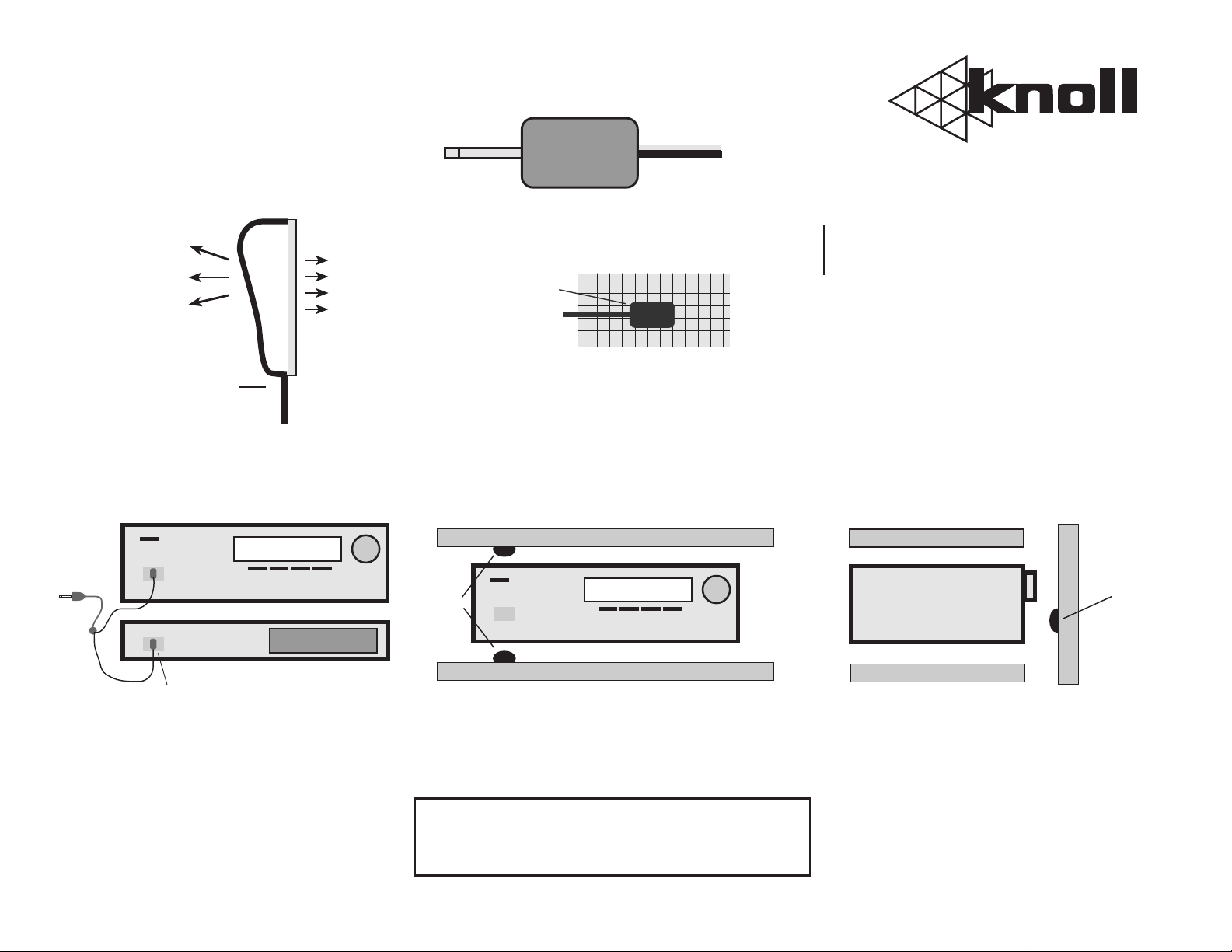
IR34 Plug and Wire Polarity
IR34 Enlarged Side View
High output side.
Used when IR34
is not stuck on
component IR
window. Controls
components up
to 3’ (1m) away.
Wire
Typical Installation
To IR55
connection
block
CD Player
Receiver
Tip
+ - +
Low output side.
Clear adhesive layer.
Stick this side to
component window.
Replace adhesive if
necessary.
To block remote control signals from other
emitters or local remote controls cut black
window mask to the component window size
and also cover IR34 cover plate.
IR34
Wire
Black Window Mask
IR34
Cabinet Installation
Shelf
Receiver
-
IR34
DUAL MINI INFRARED
Information and
Installation Guide
Cabinet Installation
Receiver
side view
EMITTER
Shelf
IR34
Infared emitters low output
(flat) side attached directly
to IR sensor windows.
Note: In this mode, other IR
signals can pass through IR34’s
and control component. To stop
this cover the IR34’s and component
sensor window with black tape.
Shelf
Note: In this mode, an emitter is
placed at the front of the shelf either
above or below the IR window. It is
less reliable than direct attachment
but looks better.
Caution: Emitters can easily be
destroyed by connecting them
directly to a power supply or battery.
Shelf
Equipment
Rack Door
Note: In this mode, an emitter
is attached to the door of the
equipment rack with the high
output side facing the component
IR window. Obviously the emitter
will be less reliable when the rack
door is open .
 Loading...