

Page 1
1080p DLP
Front Projector
User's Manual
1080p DLP Front Projector
Page 2

PREFACE
Preface
ENGLISH
ABOUT THIS MANUAL
This manual is designed for use with the 1080p DLP Front Projector. Information in this document has
been carefully checked for accuracy; however, no guarantee is given to the correctness of the
contents. The information in this document is subject to change without notice.
COPYRIGHT
© Copyright 2009
This document contains proprietary information protected by copyright. All rights are reserved. No part
of this manual may be reproduced by any mechanical, electronic or other means, in any form, without
prior written permission of the manufacturer.
TRADEMARKS
All trademarks and registered trademarks are the property of their respective owners.
FCC COMPLIANCE
This device complies with Part 15 of the FCC Rules. Operation is subject to the following two
conditions:
(1) This device may not cause harmful interference, and
(2) This device must accept any interference received, including interference that may cause
undesired operation.
FEDERAL COMMUNICATIONS COMISSION (FCC) STATEMENT
This equipment has been tested and found to comply with the limits for a Class B digital device,
pursuant to part 15 of the FCC Rules. These limits are designed to provide reasonable protection
against harmful interference in a residential installation. This equipment generates, uses and can
radiate radio frequency energy and, if not installed and used in accordance with the instructions, may
cause harmful interference to radio communications. However, there is no guarantee that interference
will not occur in a particular installation. If this equipment does cause harmful interference to radio or
television reception, which can be determined by turning the equipment off and on, the user is
encouraged to try to correct the interference by one or more of the following measures:
Reorient or relocate the receiving antenna.
Increase the separation between the equipment and the receiver.
Connect the equipment to an outlet on a circuit different from that to which the receiver is connected.
Consult the dealer or an experienced radio/TV technician for help.
1
Page 3
Notices
WARNING! To meet FCC requirements, a shielded power cord is required in order to prevent
interference. It is essential that only the supplied power cord is to be used. Use only shielded
cables to connect I/O devices to this equipment. You are cautioned that changes or
modifications not approved by the party responsible for compliance could void your authority
to operate the equipment.
WARNING! The projector cooling fan continues to run for approximately 90 seconds after the
projector is turned off using the Power button on the control panel or remote control. Never
unplug the power cable to power off the projector; damage to the lamp may result.
WARNING! High brightness light source. Do not stare into the beam of light, or view directly.
Be especially careful and ensure that children do not stare directly into the beam
of light.
PREFACE
WARNING! To reduce the risk of fire or electric shock, do not expose this product to rain or
moisture.
CAUTION! For minimal servicing and to maintain high image quality, we recommend that you
use the projector in an environment that is smoke and dust free. When used in areas where
there is a lot of smoke or dust, the filter and lens should be cleaned often to lengthen the
service life of the projector.
WARNING! Some IC chips in this product include confidential and/or trade secret property
belonging to Texas Instruments. Therefore you may not copy, modify, adapt, translate,
distribute, reverse engineer, reverse assemble or decompile the contents thereof.
WARNING! The ventilation slots, lamp, and objects next to them may get extremely hot
during operation. Do not touch these areas until they have sufficiently cooled down.
2
Page 4
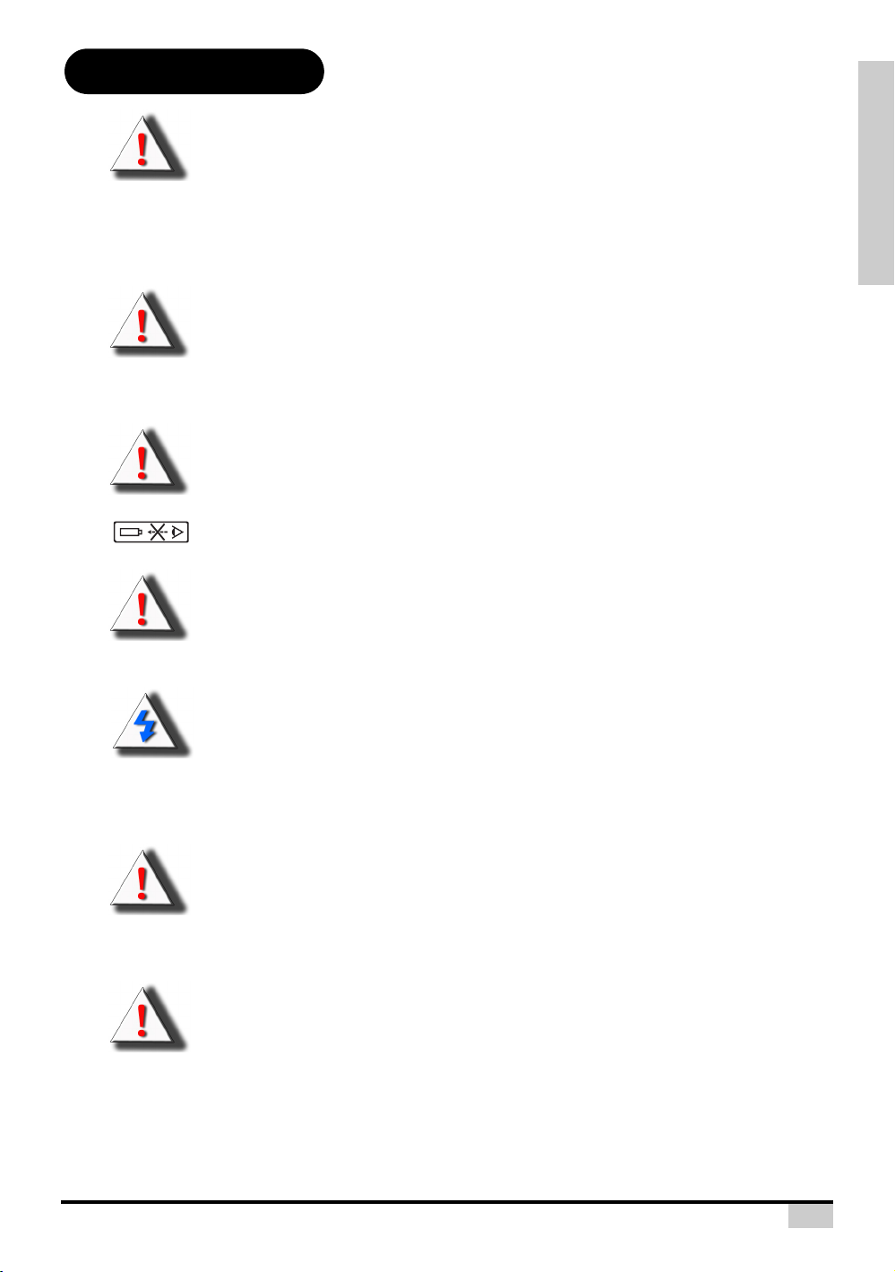
PRODUCT DISPOSAL
Wall
or
Block
Exhaust Vent
This projector utilizes a tin-lead solder, P-VIP Lamp containing a small amount of mercury. Disposal of
these materials may be regulated due to environmental considerations.
IMPORTANT RECYCLING INSTRUCTIONS
PREFACE
Hg
Lamp(s) inside this product contain mercury. This product may contain other electronic waste that can be hazardous if not disposed of properly. Recycle or dispose in
accordance with local, state, or federal Laws. For more information, contact the Electronic Industries Alliance at WWW.EIAE.ORG.
For lamp specific disposal information check WWW.LAMPRECYCLE.ORG.
Caution regarding the exhaust of the projector.
Do not place the projector in space that is poorly ventilated or confined. Allow at leat 50 cm clearance
from walls and free air flow around the projector.
Before using the projector, please read this operation manual carefully.
To facilitate reporting the loss or theft of your Projector, record the Serial Number located on the
bottom of the projector and retain this information. Before recycling the packaging, be sure that you
have checked the contents of the carton thoroughly against the list of
“Package Contents” on page 7.
WARRANTY
Promptly register the Projector’s Warranty using the REGISTRATION CARD packed with the
projector. The Warranty assures that you immediately receive the full benefit of the parts, service and
labor warranty applicable to your purchase.
SYMBOL EXPLANATIONS
DISPOSAL:
Do not use household or municipal waste collection services for disposal of electrical and electronic equipment. EU countries require the use of separate recycling
collection services.
3
Page 5

Contents
Preface .............................................................................. 1
Notices .............................................................................. 2
Introduction
Package Contents ............................................................. 7
Features ............................................................................ 8
Components ...................................................................... 9
Using the Remote Control ............................................... 12
Connections and Setup
Connecting the Projector to Other Devices ..................... 14
Connecting to Video Equipment...................................... 15
Connecting the Projector to a Computer ......................... 17
Connecting the Thumbscrew Cables............................... 18
“Plug and Play” Function ................................................. 18
Using the Adjustment Feet .............................................. 19
Adjusting the Lens........................................................... 20
Using the Lens Shift ........................................................20
Setting up the Screen...................................................... 21
INTRODUCTION
Projector (Front and Top View)............................. 9
Projector (Rear View).......................................... 10
Remote Control ................................................... 11
Available Range of the Remote Control .............. 12
Inserting the Batteries ......................................... 12
Before Setting Up................................................ 14
Connecting the Power Cord ................................ 14
Connecting to Video Equipment.......................... 15
Connecting to Component Video Equipment ...... 16
Connecting by Using a HDMI to HDMI Cable ..... 16
Connecting to a Computer .................................. 17
Screen Size and Projection Distance
(Short throw lens) ............................................... 22
Screen Size and Projection Distance
(Long throw lens) ................................................ 23
Projection from behind the screen ...................... 24
Basic Operation
Image Projection ............................................................. 26
Basic Procedure.................................................. 26
Selecting the On-screen Display Language ........ 28
Menu Bar Items ............................................................... 29
Using the Menu Screen................................................... 30
Menu Selections (Adjustments) .......................... 30
Adjusting the Picture .......................................................31
Adjusting Image Preferences .............................. 31
Adjusting Computer Images ............................................ 35
Easy to Use Functions
Selecting the Picture Display Mode................................. 37
Overscan Type ................................................................ 40
Overscan Adjust ..............................................................40
4
Page 6

H-V Position Function...................................................... 41
H-V Keystone Function ................................................... 42
Selecting the Economy Mode.......................................... 43
Sync Threshold ............................................................... 44
Automatic Power OFF Function ...................................... 44
Source Select .................................................................. 45
OSD Time Out................................................................. 45
OSD Blending.................................................................. 46
INTRODUCTION
Film Mode........................................................................ 46
STI................................................................................... 47
Noise Reduction .............................................................. 48
Blank Screen ................................................................... 48
Reset ...............................................................................49
Reversing/Inverting Projected Images............................. 49
Lamp Timer Reset........................................................... 50
Status .............................................................................. 50
Input Source .................................................................... 51
Factory reset ...................................................................51
Appendix
Maintenance.................................................................... 53
Cleaning the Ventilative Holes ........................................54
About the Lamp ............................................................... 55
Removing and Installing the Lamp Unit........................... 57
Resetting the Lamp Timer ............................................... 58
Connecting Pin Assignments .......................................... 59
Computer Compatibility Chart ......................................... 60
Video Compatibility Chart................................................61
Troubleshooting............................................................... 62
Product Specifications..................................................... 64
Short Throw Lens Dimension ..........................................65
Long Throw Lens Dimension........................................... 66
Setting the Power Save....................................... 43
Setting the PRJ Mode ......................................... 49
Cleaning the Ventilative Holes ............................ 54
Caution Concerning the Lamp ............................55
Replacing the Lamp ............................................ 55
Temperature LED (Over Temperature)............... 56
5
Page 7

Introduction
INTRODUCTION
6
Page 8
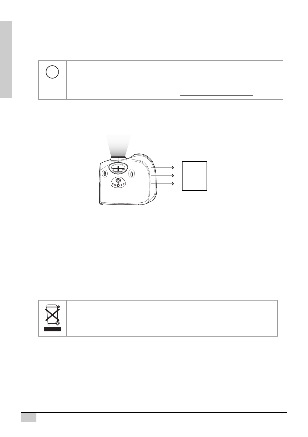
Package Contents
Open the package and ensure that you have the following items:
1
T
U
P
N
I
2
T
U
P
N
I
3
T
U
P
N
I
4
T
U
P
IN
INTRODUCTION
Remote control Two “AAA” size
RS232 cable Quick Guide CD with User’s Manual
HDMI to HDMI cable (3M) Composite cable
Optional accessories
VGA to VGA cable
Ceiling mount package
Component cable
S-Video cable
Note
• Some of the cables may not be available depending on the region. Please check with
your nearest Authorized Dealer.
batteries
WXGA/720p
DLP FRONT PR
Q
u
ic
k
G
u
id
e
T
h
i
s
m
a
n
u
a
l
m
a
y
n
o
t
b
©
e
A
c
o
l
p
l
i
e
r
i
d
g
i
n
h
t
a
s
n
y
r
e
m
s
e
e
d
i
r
a
v
o
e
r
d
f
o
.
r
m
w
i
t
h
o
u
t
t
h
e
w
r
i
t
t
e
n
c
o
n
s
e
n
t
o
f
t
h
e
m
a
n
u
(3.6M)
Power cord
(By country)
OJECT
O
R
f
a
c
t
u
r
e
r
.
If anything is missing or appears damaged, contact your dealer immediately.
7
Page 9

Features
• Newly developed 0.65-inch 1080p DMD™ chip provides significantly improved optical efficiency and excellent contrast ratio.
• Newly developed LVDS (Low voltage differential signal) chip eliminates Color Breaking phenomena common with previous generation DLP™ projectors.
• Use of high-output lamp realizes both high color purity and high brightness. Natural images
made possible by high color reproducibility can be created with high-brightness, powerful
expression capabilities.
• New i/p conversion algorithm enhances the performance of the motion detect i/p conversion.
• Extensive improvements on the jagged edges or slanted lines in moving images.
• New Edge Up-Scaling.
• As a result of reducing jagged edges and flickering when up-scaling edges of slanted lines,
even signals not reaching a panel resolution of 480i/p can be projected by converting them to
1920X1080 resolution images.
• New Film Mode Function.
• 3:2 pull down enhancement for 480i and 2:2 for 576i signals, but HDTV 1080i signals as well.
• Use of a HDMI/HDCP terminal enables all processes from input to signal processing and projection to be performed digitally, resulting in the realization of all-digital projection without any
data loss due to analog conversion. This also supports the building of home theaters using
HTPC.
• Provides the new Brilliant Color™ algorithm which provides enhancement to the functions of
degamma, and Spoke light recapture.
INTRODUCTION
8
Page 10
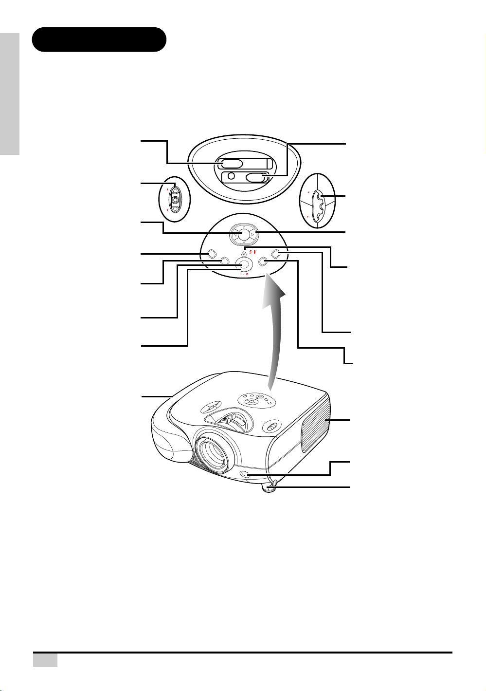
Components
ENTER button
For setting the selected items
or adjustments from the menu.
Zoom ring
Adjust screen display
Focus ring
Adjust focus.
Power (ON/OFF) buttons
For turning the power on or
off.
Intake vent
Adjustment foot
Remote control sensor
Exhaust vent
Adjustment buttons
(T,S,W,X)
For selecting menu items.
Temperature indicator
This indicator glows red, when
the temperature of the
projector exceeds the set
critical temperature or when
the fan functions abnormally.
MENU button
Press this button to enter
the OSD menus.
INPUT button
Press this button to select
the input source.
ECO button
For power saving/extended
lamp life.
Exit button
For exiting the OSD.
Lens shift dial
(Horizontal)
Lens shift dial
(Vertical)
Power indicator
Blue: The power is ready.
Blue blinking: The fan is
cooling.
Projector (Front and Top View)
INTRODUCTION
(V)
LENS SHIFT
Focus
Zoom
(H)
ENTER
STATUS
EXIT
ECO
MENU
INPUT
LENS SHIFT
Temperature indicator
The projector has an over temperature warning LED on the control panel. If the projector overheats because
of a dirty filter or another problem, the LED will light up, and the projector lamp will turn off, after which a 90second cooling off period occurs. After restarting the projector, if the unit doesn’t operate normally, take the
projector in for servicing.
9
Page 11
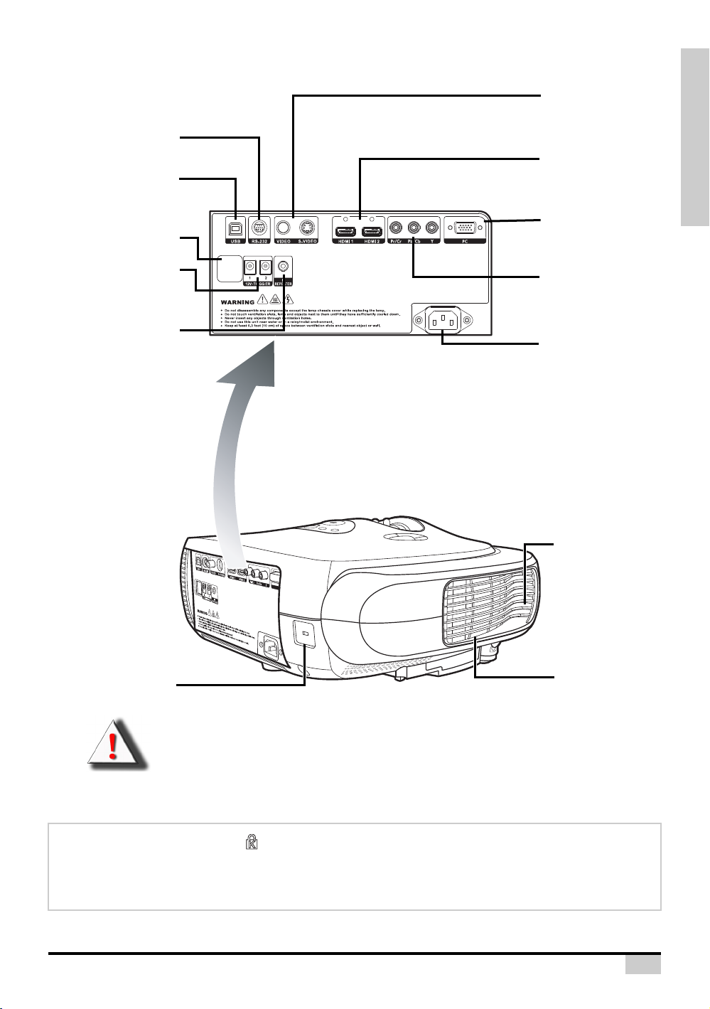
Projector (Rear View)
Exhaust vent
Kensington Security
Standard connector
Exhaust vent
Remote control sensor
AC socket
Input: 100~240VAC
3.5A,50/60Hz.
Input 1: Component
Terminals for YPbPr/
YCbCr.
Input 4: PC
Terminal for connecting
PC RGB signals.
RS-232C terminal
Command control.
12V Trigger
Terminals for screen
controlling.
Input 3:
Video/S-Video
Terminals for connecting
Video/S-Video.
Input 2: HDMI
Terminals for connecting
HDMI.
USB
B type terminal for
service port.
IR Repeater
Terminal for wired
remote control.
INTRODUCTION
WARNING! As the projector lamp becomes extremely hot, air blowing out from the ventilation
slots can be uncomfortably hot.
Using the Kensington Lock
This projector has a Kensington Security Standard connector for use with a Kensington MicroSaver
Security System. Refer to the information that came with the system for instructions on how to use it to
secure the projector.
10
Page 12
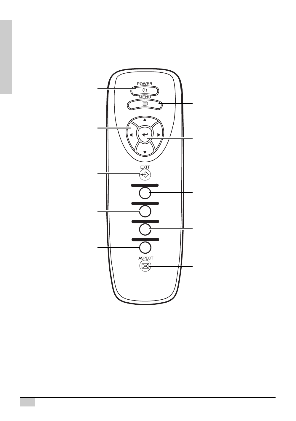
Remote Control
Power (ON/OFF) button
For turning the power on and off.
EXIT button
For Exiting the OSD.
Adjustment buttons
(T,S,W,X)
For displaying adjustment
and setting screens.
MENU button
Press this button to
enter the OSD menus.
INPUT 1 button
Selects the source Component
RCA / SCART.
INPUT 2 button
Selects the source HDMI 1 or 2.
INPUT 3 button
Selects the source Video or S-Video.
INPUT 4 button
Selects the source PC.
Aspect Ratio button
Controls how the projector resizes
the input image.
ENTER button
For setting the selected
items or adjustments from
the menu.
INTRODUCTION
INPUT 1
INPUT 2
INPUT 3
INPUT 4
11
Page 13
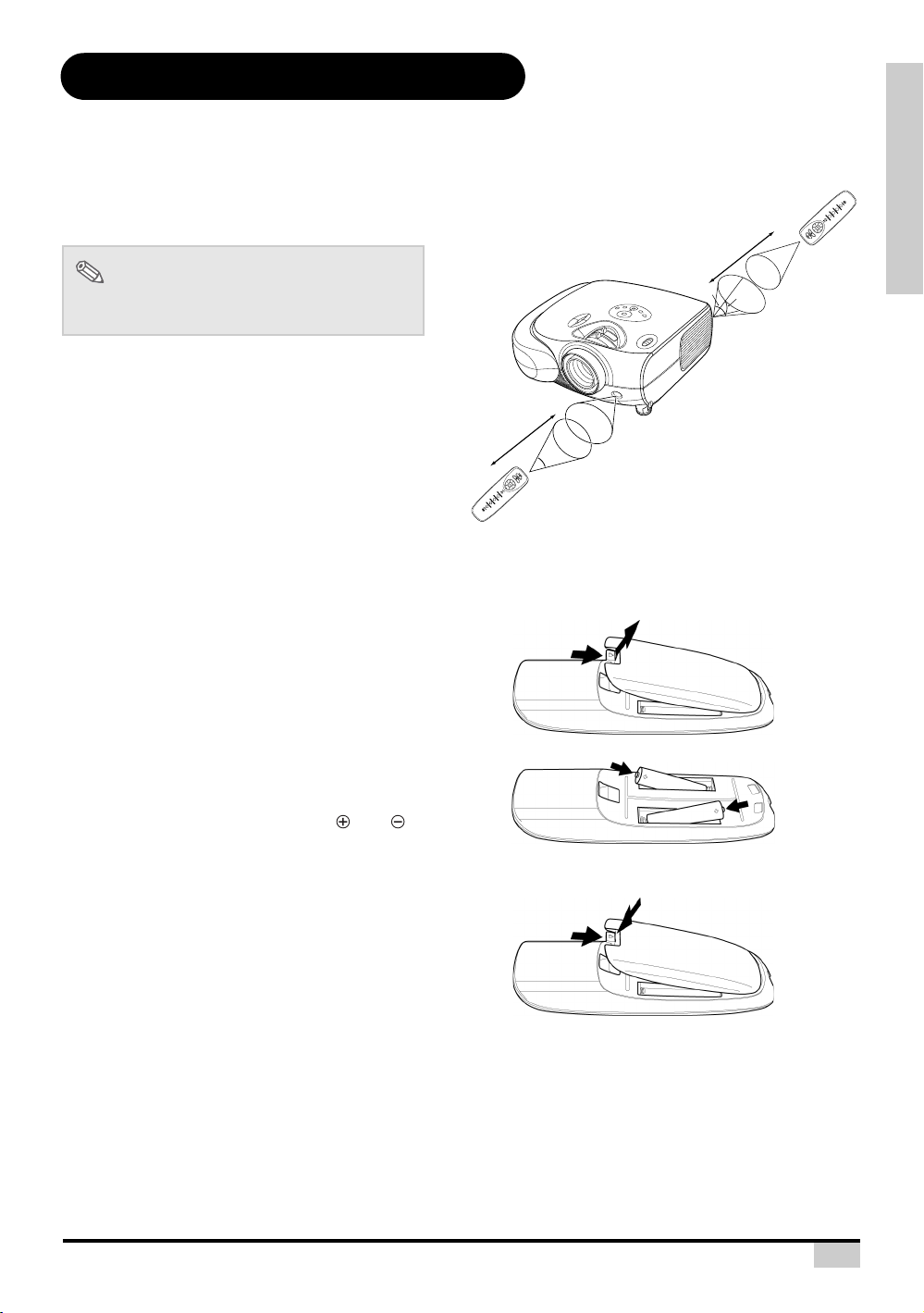
Using the Remote Control
Available Range of the Remote Control
INTRODUCTION
The remote control can be used to control the
projector within the ranges shown in the
illustration.
Note
• The signal from the remote control can be
reflected by the screen.
When using the remote control:
• Be sure not to drop it, or expose it to moisture
or high temperature.
• The remote control may malfunction under a
23'(7 m)
fluorescent lamp. If that occurs, move the
projector away from the fluorescent lamp.
Inserting the Batteries
The batteries (two “AAA” size) are included in the package.
Press down the tab on the cover
1
and pull the cover towards the
direction of the arrow.
T 4
U
INP
3
T
NPU
I
2
T
NPU
I
1
T
NPU
I
23'(7 m)
45°
45°
30°
INPUT
1
INPUT 2
IN
PUT 3
INPUT 4
30°
30°
Insert the included batteries.
2
Insert the batteries making sure the
polarities correctly match the and
marks inside the battery compartment.
Insert the lower tab of the cover
3
into the opening, and press down
the cover until it clicks in place.
12
Page 14

Connections and Setup
CONNECTIONS AND SETUP
13
Page 15
Connecting the Projector to Other Devices
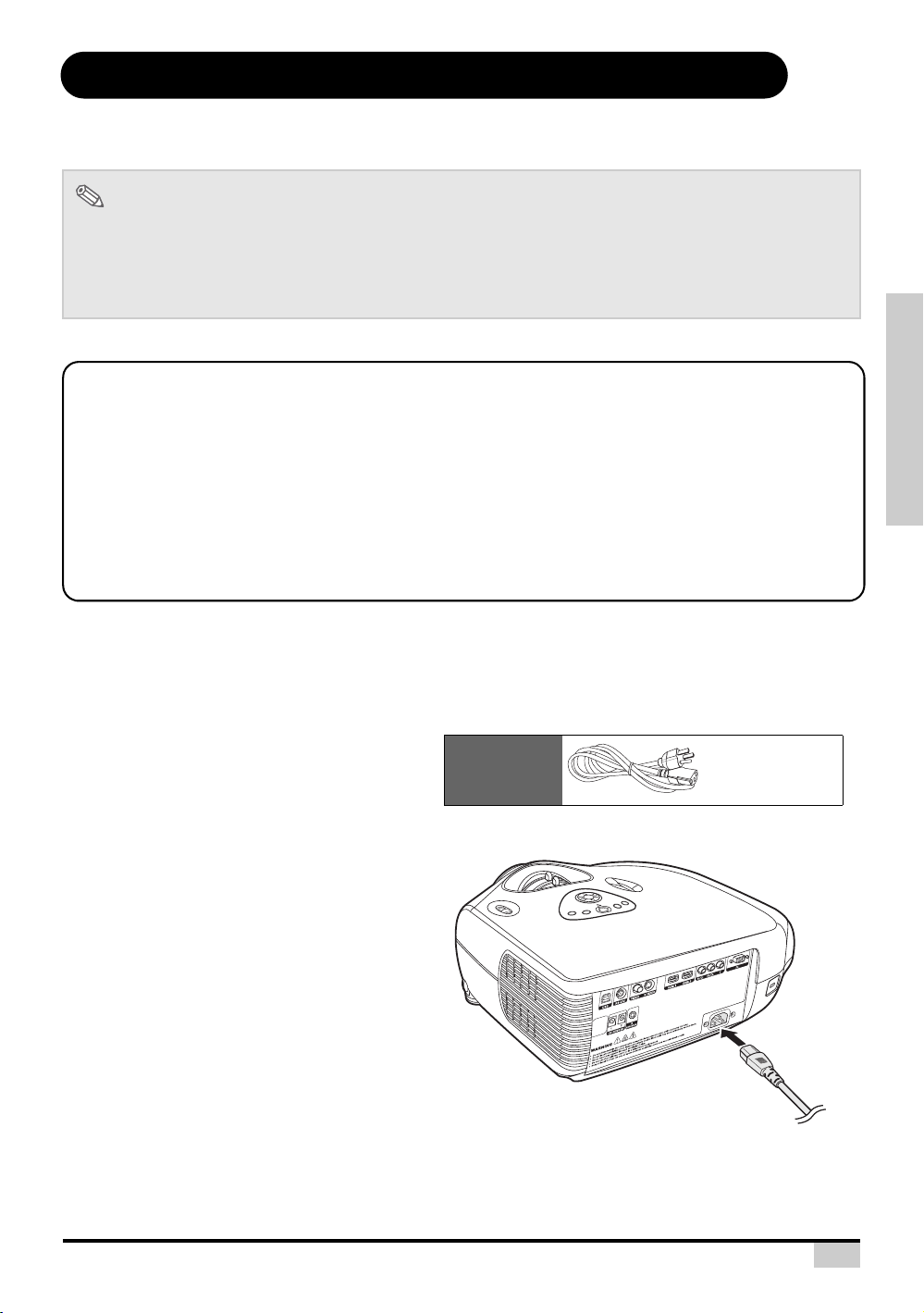
Supplied
accessory
Power cord
Before Setting Up
Note
• Before connecting, be sure to turn off both the projector and the devices to be connected. After making
all connections, turn on the projector and then the other devices.
When connecting a computer, be sure that it is the last device to be turned on after all the connections
are made.
• Be sure to read the operation manuals of the devices to be connected before making connections.
This projector can be connected to
Video equipment:
A VCR, Laser disc player or other video equipment.
A DVD player or DTV* decoder.
*DTV is the umbrella term used to describe the new digital television system in the United States.
A computer using:
HD 15-pin VGA to VGA cable (optional item, sold separately).
CONNECTIONS AND SETUP
Connecting the Power Cord
Plug in the supplied power cord into the
AC socket on the rear of the projector.
14
Page 16
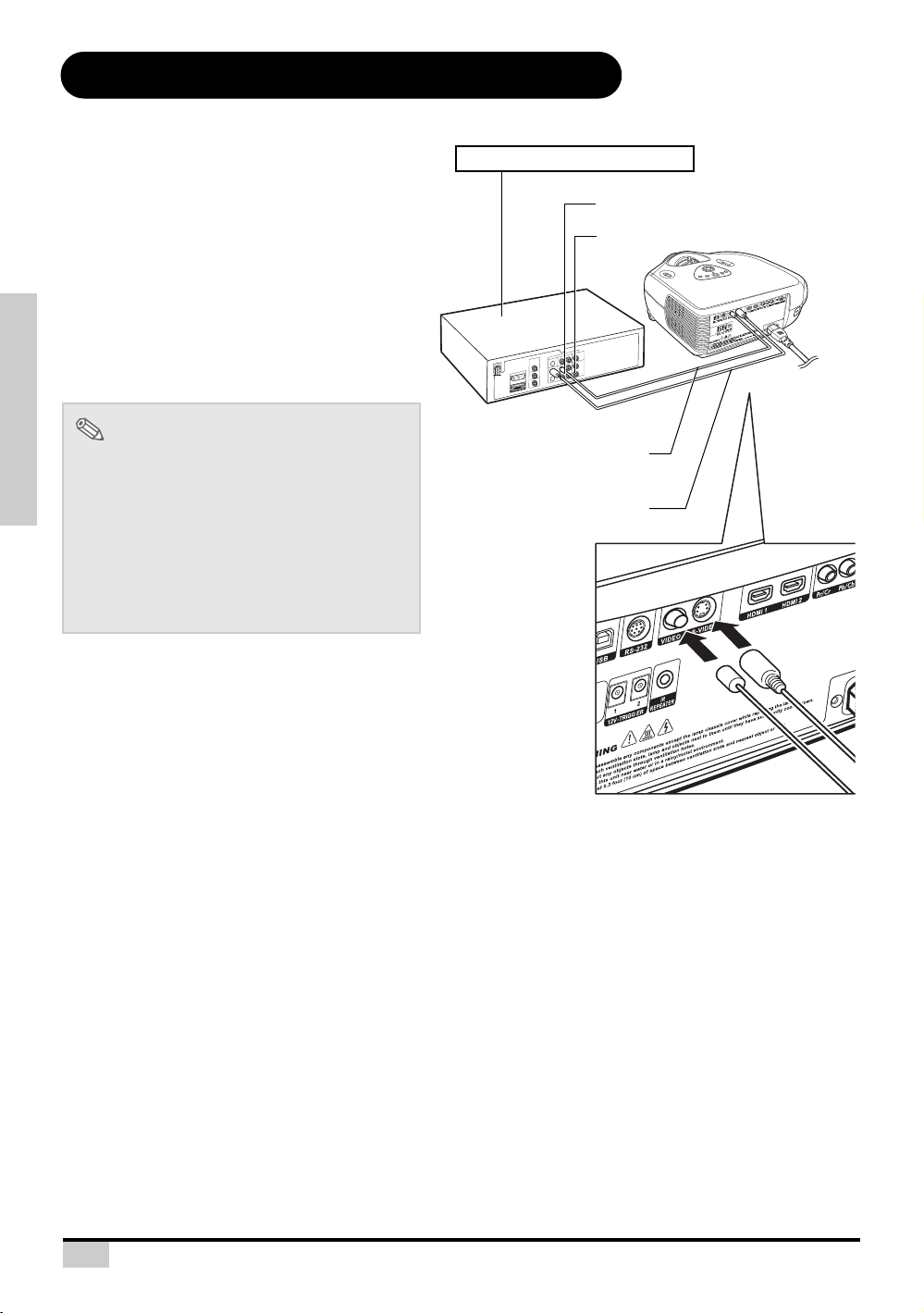
Connecting to Video Equipment
To S-Video output terminal
To Video output terminal
VCR or other video equipment
Composite video cable
S-Video cable
(commercially available)
Connecting to Video Equipment
Using an S-Video or a Composite Video
Cable
Using an S-Video or a Composite video cable,
a VCR, laser disc player or other video
equipment can be connected to INPUT 3 input
terminals.
Note
• The INPUT 3 (S-VIDEO) terminal uses a
video signal system in which the picture is
separated into color and luminance signals
CONNECTIONS AND SETUP
to realize a higher-quality image. To view a
higher-quality image, use a commercially
available S-Video cable to connect the
INPUT 3 terminal on the projector and the
S-Video output terminal on the video
equipment.
15
Page 17
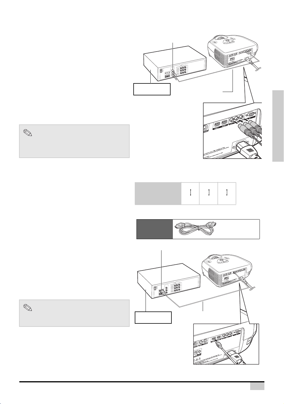
DVD player or
DTV* decoder
To analog component
output terminal
Component cable
(commercially available)
Projector Y
Y
PB
CB
PR
CR
DVD player or
DTV decoder
Supplied
accessory
HDMI to HDMI
cable
DVD player or
DTV* decoder
HDMI to HDMI cable
To HDMI output terminal
Connecting to Component Video Equipment
Using a Component Cable (INPUT 1)
Use a component cable when connecting to
the INPUT 1 terminal and component video
equipment such as DVD players and DTV*
decoders.
*DTV is an umbrella term used to describe the
new digital television system in the United
States.
Note
• When connecting the projector to the video
equipment in this way, select “Component”
for “Input Source” in the “Main” menu.
CONNECTIONS AND SETUP
The component jack for a DVD and so forth may be
indicated with Y, CB or CR. Connect each jack as shown
below.
Connecting by Using a HDMI to HDMI Cable
Use an HDMI to HDMI cable when connecting
HDMI video equipment such as DVD players
to INPUT 2 terminal.
Connect an HDMI to HDMI cable
1
to the projector.
Connect the above cable to the
2
video equipment.
Note
• Select the input signal type of the video
equipment.
16
Page 18
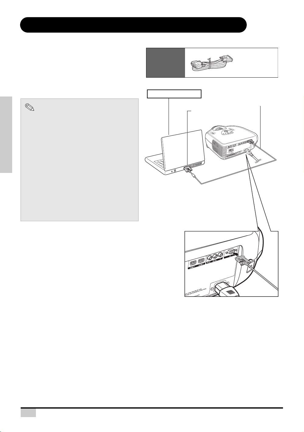
Connecting the Projector to a Computer
Optional
accessory
HD 15-pin
VGA to VGA
cable
To VGA output terminal
Notebook Computer
HD 15-pin VGA to VGA cable
(sold separately)
Connecting to a Computer
Connect the projector to the computer
using the HD 15-pin VGA to VGA cable.
• Secure the connectors by tightening the
thumbscrews.
Note
• See page 60 “Computer Compatibility
Chart” for a list of computer signals
compatible with the projector. Use with
computer signals other than those listed
may cause some of the functions not to
work.
• A Macintosh adaptor may be required for
use with some Macintosh computers.
CONNECTIONS AND SETUP
Contact your nearest Authorized Service
Center or Dealer.
• Depending on the computer you are using,
an image may not be projected unless the
signal output setting of the computer is
switched to the external output. Refer to the
computer operation manual for switching
the computer signal output settings.
17
Page 19
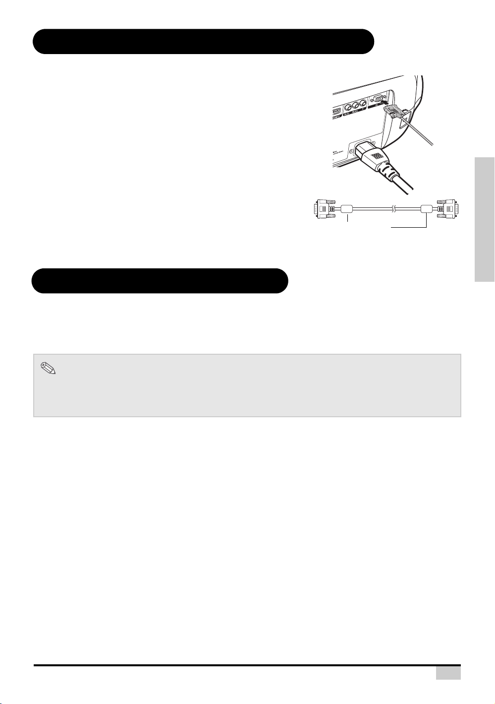
Connecting the Thumbscrew Cables
Ferrite core
Connect the thumbscrew cable making sure that it fits correctly
into the terminal. Then, firmly secure the connectors by tightening
the screws on both sides of the plug.
Do not remove the ferrite core attached to the HD 15-pin VGA
cable.
“Plug and Play” Function
This projector is compatible with VESA-standard DDC 1/DDC 2B. The projector and a VESA DDC
compatible computer will communicate their setting requirements, allowing for quick and easy setup.
Before using the “Plug and Play” function, be sure to turn on the projector first and the connected
computer last.
CONNECTIONS AND SETUP
Note
• The DDC “Plug and Play” function of this projector operates only when used in conjunction with a VESA
DDC compatible computer.
18
Page 20
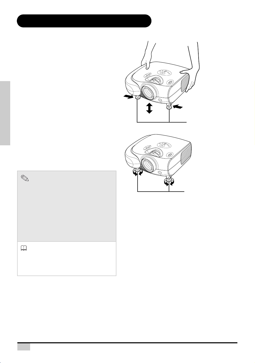
Using the Adjustment Feet
Foot releases
Adjustment feet
The height of the projector can be adjusted
using the adjustment feet when the surface
the projector is placed on is uneven or when
the screen is slanted.
The projection of the image can be made
higher by adjusting the projector when it is in a
location lower than the screen.
Press the foot releases and lift
1
the projector to the desired
angle.
Remove your hands from the foot
2
releases. Once the adjustment
feet have locked in position,
CONNECTIONS AND SETUP
place the projector down.
• If the screen is at an angle, the
adjustment feet can be used to adjust
the angle of the image.
Note
• The projector is adjustable up to
approximately 11 degrees from the standard
position.
• When the height of the projector is adjusted,
the image may become distorted
(keystoned), depending on the relative
positions of the projector and the screen.
See page 42 for details on keystone
correction.
Info
• When lowering the projector, be careful not
to get your finger caught in the area
between the adjustment foot and the
projector.
19
Page 21
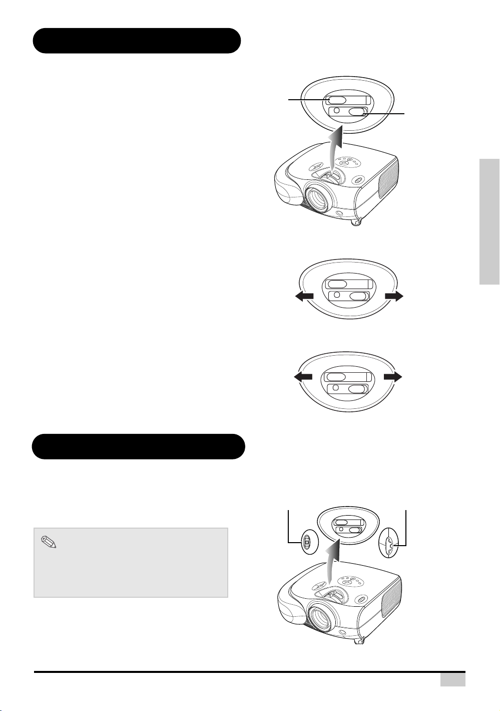
Adjusting the Lens
Focus ring
Zoom ring
Zoom ring
Z
o
o
m
i
n
Z
o
o
m
o
u
t
Focus ring
Lens shift dial
(Horizontal)
Lens shift dial
(Vertical)
The image is focused and adjusted to the
desired size using the focus ring or zoom ring
on the projector.
Zoom is adjusted by rotating the
1
zoom ring.
Focus is adjusted by moving the
2
focus ring.
Focus
Zoom
CONNECTIONS AND SETUP
Using the Lens Shift
The height and width of the projected image
can be adjusted to be within the shift range of
the lens by rotating the lens shift dial at the top
of the projector.
Note
• Do not forcibly turn the lens shift dial beyond
the range of the upper left and lower right
positions. This may cause the projector to
malfunction.
20
Page 22

Setting up the Screen
Side View
Top Vi e w
2
1
V
H
V
2
1
H
Position the projector perpendicular to the screen with all feet flat and level to achieve an optimal image.
Note
• The projector lens should be centered in the middle of the screen. If the horizontal line passing through
the lens center is not perpendicular to the screen, the image will be distorted, making viewing difficult.
• For an optimal image, position the screen so that it is not in direct sunlight or room light. Light falling
directly on the screen washes out the colors, making viewing difficult. Close the curtains and dim the
lights when setting up the screen in a sunny or bright room.
• A polarizing screen cannot be used with this projector.
Standard Setup (Front Projection)
Place the projector at the required distance from the screen
according to the desired picture size. (See page 22)
An Example of Standard Setup
CONNECTIONS AND SETUP
• The distance from the screen to the projector may
vary depending on the size of the screen.
90
• The default setting can be used, when placing the
projector in front of the screen. If the projected
image is reversed or inverted, readjust the setting to
Audience
“Front” for “PRJ Mode” in the “Options” menu.
• Place the projector so that an imaginary horizontal
line that passes through the center of the lens is
90
H
perpendicular to the screen.
Note
2D Lens Shift Ability:
• Short throw lens shift:
1/2 of screen height: Up 100%, Down 60%
1
V
2
V
1/2 of screen height: Left 15%, Right 15%
• Long throw lens shift:
1/2 of screen height: Up 140%, Down 60%
1/2 of screen height: Left 15%, Right 15%
• It is recommended that images be projected onto the
dashed line octagonal area for fine image quality.
1
H
2
• There is a tolerance of 5% in the formula above.
21
Page 23

Screen Size and Projection Distance
The formula for screen size and projection distance
Wide Screen 16:9
Screen Size Throw Distance
Center of lens to edge of
screen bottom
Diagonal Wide High Max Min Up down
in cm in cm in cm ft m ft m ft cm ft cm
300.0 762.0 261.5 664.1 147.1 373.6 36.2 11.0 29.0 8.8 0.0 0.0 -9.8 -298.9
250.0 635.0 217.9 553.5 122.6 311.3 30.1 9.2 24.1 7.4 0.0 0.0 -8.2 -249.1
200.0 508.0 174.3 442.8 98.1 249.1 24.1 7.3 19.3 5.9 0.0 0.0 -6.5 -199.2
150.0 381.0 130.7 332.1 73.5 186.8 18.1 5.5 14.5 4.4 0.0 0.0 -4.9 -149.4
133.0 337.8 115.9 294.4 65.2 165.6 16.0 4.9 12.8 3.9 0.0 0.0 -4.3 -132.5
106.0 269.2 92.4 234.7 52.0 132.0 12.8 3.9 10.2 3.1 0.0 0.0 -3.5 -105.6
100.0 254.0 87.2 221.4 49.0 124.5 12.1 3.7 9.7 2.9 0.0 0.0 -3.3 -99.6
92.0 233.7 80.2 203.7 45.1 114.6 11.1 3.4 8.9 2.7 0.0 0.0 -3.0 -91.7
84.0 213.4 73.2 186.0 41.2 104.6 10.1 3.1 8.1 2.5 0.0 0.0 -2.7 -83.7
72.0 182.9 62.8 159.4 35.3 89.7 8.7 2.6 7.0 2.1 0.0 0.0 -2.4 -71.7
60.0 152.4 52.3 132.8 29.4 74.7 7.2 2.2 5.8 1.8 0.0 0.0 -2.0 -59.8
50.0 127.0 43.6 110.7 24.5 62.3 6.0 1.8 4.8 1.5 0.0 0.0 -1.6 -49.8
Y1 (Max.) = 0.12057x
Y2 (Min.) = 0.09660x
Z1 (Upper) = 0.00000x
z2 (Lower) = -0.03268x
x : Screen size (diag.)
y : Projection distance
z : Distance from the lens center to the
lower edge of the image
Note
• There is a tolerance of ±3% in the formula above.
• Values with a minus (-) sign indicate the distance of the lens center below the
bottom of the image.
The formula for screen size and projection distance
Standard Screen 4:3
Screen Size Throw Distance
Center of lens to edge of
screen bottom
Diagonal Wide High Max Min Up down
in cm in cm in cm ft m ft m ft cm ft cm
300.0 762.0 240.0 609.6 180.0 457.2 33.2 10.1 26.6 8.1 0.0 0.0 -12.0 -365.8
250.0 635.0 200.0 508.0 150.0 381.0 27.7 8.4 22.2 6.8 0.0 0.0 -10.0 -304.8
200.0 508.0 160.0 406.4 120.0 304.8 22.1 6.7 17.7 5.4 0.0 0.0 -8.0 -243.8
150.0 381.0 120.0 304.8 90.0 228.6 16.6 5.1 13.3 4.1 0.0 0.0 -6.0 -182.9
133.0 337.8 106.4 270.3 79.8 202.7 14.7 4.5 11.8 3.6 0.0 0.0 -5.3 -162.2
106.0 269.2 84.8 215.4 63.6 161.5 11.7 3.6 9.4 2.9 0.0 0.0 -4.2 -129.2
100.0 254.0 80.0 203.2 60.0 152.4 11.1 3.4 8.9 2.7 0.0 0.0 -4.0 -121.9
92.0 233.7 73.6 186.9 55.2 140.2 10.2 3.1 8.2 2.5 0.0 0.0 -3.7 -112.2
84.0 213.4 67.2 170.7 50.4 128.0 9.3 2.8 7.4 2.3 0.0 0.0 -3.4 -102.4
72.0 182.9 57.6 146.3 43.2 109.7 8.0 2.4 6.4 1.9 0.0 0.0 -2.9 -87.8
60.0 152.4 48.0 121.9 36.0 91.4 6.6 2.0 5.3 1.6 0.0 0.0 -2.4 -73.2
50.0 127.0 40.0 101.6 30.0 76.2 5.5 1.7 4.4 1.4 0.0 0.0 -2.0 -61.0
Y1 (Max.) = 0.11067x
Y2 (Min.) = 0.08867x
Z1 (Upper) = 0.00000x
Z2 (Lower) = -0.03268x
x : Screen size (in)
y : Projection distance (ft)
z : Distance from the lens center to the
lower edge of the image(in)
Note
• There is a tolerance of ±3% in the formula above.
• Values with a minus (-) sign indicate the distance of the lens center below the
bottom of the image.
(Short throw lens)
When using a wide
screen (16:9)
In case of displaying the
16:9 picture on the whole
area of the 16:9 screen.
16
9
: Picture area
CONNECTIONS AND SETUP
When using a normal
screen (4:3)
In case of setting the
16:9 picture to the full
horizontal width of the 4:3
screen.
4
: Screen area
: Picture area
3
22
Page 24

Screen Size and Projection Distance
The formula for screen size and projection distance
Wide Screen 16:9
Screen Size Throw Distance
Center of lens to edge of
screen bottom
Diagonal WIde High Max Min Up down
in cm in cm in cm ft m ft m ft cm ft cm
300.0 762.0 261.5 664.1 147.1 373.6 45.5 13.9 36.2 11.0 2.5 74.7 -9.8 -298.9
250.0 635.0 217.9 553.5 122.6 311.3 37.9 11.6 30.1 9.2 2.0 62.3 -8.2 -249.1
200.0 508.0 174.3 442.8 98.1 249.1 30.4 9.3 24.1 7.3 1.6 49.8 -6.5 -199.2
150.0 381.0 130.7 332.1 73.5 186.8 22.8 6.9 18.1 5.5 1.2 37.4 -4.9 -149.4
133.0 337.8 115.9 294.4 65.2 165.6 20.2 6.2 16.0 4.9 1.1 33.1 -4.3 -132.5
106.0 269.2 92.4 234.7 52.0 132.0 16.1 4.9 12.8 3.9 0.9 26.4 -3.5 -105.6
100.0 254.0 87.2 221.4 49.0 124.5 15.2 4.6 12.1 3.7 0.8 24.9 -3.3 -99.6
92.0 233.7 80.2 203.7 45.1 114.6 14.0 4.3 11.1 3.4 0.8 22.9 -3.0 -91.7
84.0 213.4 73.2 186.0 41.2 104.6 12.8 3.9 10.1 3.1 0.7 20.9 -2.7 -83.7
72.0 182.9 62.8 159.4 35.3 89.7 10.9 3.3 8.7 2.6 0.6 17.9 -2.4 -71.7
60.0 152.4 52.3 132.8 29.4 74.7 9.1 2.8 7.2 2.2 0.5 14.9 -2.0 -59.8
40.0 101.6 34.9 88.6 19.6 49.8 6.1 1.9 4.8 1.5 0.3 10.0 -1.3 -39.8
Y1 (Max.) = 0.15180x
Y2 (Min.) = 0.12057x
Z1 (Upper) = 0.00817x
Z2 (Lower) = -0.03268x
x : Screen size (in)
y : Projection distance (ft)
z : Distance from the lens center to the
lower edge of the image (in)
Note
• There is a tolerance of ±3% in the formula above.
• Values with a minus (-) sign indicate the distance of the lens center below the
bottom of the image.
The formula for screen size and projection distance
Standard Screen 4:3
Screen Size Throw Distance
Center of lens to edge of
screen bottom
Diagonal WIde High Max Min Up down
in cm in cm in cm ft m ft m ft cm ft cm
300.0 762.0 240.0 609.6 180.0 457.2 41.8 12.7 33.2 10.1 3.0 91.4 -12.0 -365.8
250.0 635.0 200.0 508.0 150.0 381.0 34.8 10.6 27.7 8.4 2.5 76.2 -10.0 -304.8
200.0 508.0 160.0 406.4 120.0 304.8 27.9 8.5 22.1 6.7 2.0 61.0 -8.0 -243.8
150.0 381.0 120.0 304.8 90.0 228.6 20.9 6.4 16.6 5.1 1.5 45.7 -6.0 -182.9
133.0 337.8 106.4 270.3 79.8 202.7 18.5 5.6 14.7 4.5 1.3 40.5 -5.3 -162.2
106.0 269.2 84.8 215.4 63.6 161.5 14.8 4.5 11.7 3.6 1.1 32.3 -4.2 -129.2
100.0 254.0 80.0 203.2 60.0 152.4 13.9 4.2 11.1 3.4 1.0 30.5 -4.0 -121.9
92.0 233.7 73.6 186.9 55.2 140.2 12.8 3.9 10.2 3.1 0.9 28.0 -3.7 -112.2
84.0 213.4 67.2 170.7 50.4 128.0 11.7 3.6 9.3 2.8 0.8 25.6 -3.4 -102.4
72.0 182.9 57.6 146.3 43.2 109.7 10.0 3.1 8.0 2.4 0.7 21.9 -2.9 -87.8
60.0 152.4 48.0 121.9 36.0 91.4 8.4 2.5 6.6 2.0 0.6 18.3 -2.4 -73.2
40.0 101.6 32.0 81.3 24.0 61.0 5.6 1.7 4.4 1.3 0.4 12.2 -1.6 -48.8
Y1 (Max.) = 0.13933x
Y2 (Min.) = 0.11067x
Z1 (Upper) = 0.00817x
Z2 (Lower) = -0.03268x
x : Screen size (in)
y : Projection distance (ft)
z : Distance from the lens center to the
lower edge of the image (in)
Note
• There is a tolerance of ±3% in the formula above.
• Values with a minus (-) sign indicate the distance of the lens center below the
bottom of the image.
(Long throw lens)
When using a wide
screen (16:9)
In case of displaying the
16:9 picture on the whole
area of the 16:9 screen.
16
9
: Picture area
CONNECTIONS AND SETUP
When using a normal
screen (4:3)
In case of setting the
16:9 picture to the full
horizontal width of the 4:3
screen.
4
: Screen area
: Picture area
23
3
Page 25

Projection from behind the screen
When using the default setting.
TOn-screen Display
The image is reversed.
When using the default setting.
TOn-screen Display
The image is reversed.
When using the default setting.
TOn-screen Display
The image is reversed.
Projecting a Reversed/Inverted Image
Place a translucent screen between the projector and the
audience.
Reverse the image by setting “Rear” for “PRJ Mode” in the
“Options” menu.
Projection using a mirror
Place a mirror (normal flat type) in front of the lens.
Reverse the image by setting “Rear” for “PRJ Mode” in the
“Options” menu, when the mirror is placed on the side
where the audience is.
CONNECTIONS AND SETUP
Info
• When using a mirror, be sure to carefully position
both the projector and the mirror so that the light
does not shine into the eyes of the audience.
Ceiling-mount setup
It is recommended that you use the optional ceiling-
mount bracket for this installation.
Before mounting the projector, contact your nearest
Authorized Service Center or Dealer to obtain the
recommended ceiling-mount bracket (sold separately).
Be sure to adjust the position of the projector to match
the distance (Z) from the lens center position to the
lower edge of the image, when mounting the projector
on the ceiling.
Invert the image by setting “Ceiling + Front” for “PRJ
Mode” in the “Options” menu.
24
Page 26

Basic Operation
Basic Operation
25
Page 27

Image Projection
T, S, W, X buttons
ENTER button
Power
button
MENU button
INPUT button
ECO button
EXIT button
Temperature Indicator
Power
indicator
(Blue)
Basic Procedure
Connect the required external equipment to
the projector before operating the following
procedures.
Info
• The language preset at the factory is
English. If you want to change the onscreen display to another language, reset
the language according to the procedure
page 28.
Plug the power cord into the wall
1
outlet.
• The power indicator illuminates blue,
and the projector enters standby
mode.
on
Basic Operation
2
Press on the remote control
or on the projector.
• The power indicator turns off.
Note
• The power indicator illuminates,
indicating the status of the lamp.
Blue: The power is ready.
Blue blinking: The fan is cooling.
EXIT
ECO
ENTER
STATUS
MENU
INPUT
26
Page 28

Press on the projector to
INPUT 1
INPUT 2
INPUT 3
INPUT 4
T, S, W, X
buttons
EXIT button
Power button
MENU button
INPUT button
INPUT 2 button
INPUT 1 button
INPUT 4 button
INPUT 3 button
About the INPUT modes
INPUT 1
Selects the source Component RCA / SCART.
INPUT 2
Selects the source HDMI
1 or 2.
INPUT 3
Selects the source Video
or S-Video.
INPUT 4 Selects the source PC.
3
INPUT
select the INPUT mode.
Note
• When a signal is not received,
“Searching for Source” will be
displayed.
INPUT
ENTER
Note
• If you select “Auto” as the input
source, then the correct input source
is selected automatically.
Basic Operation
Press on the remote control
4
or on the projector, then press
27
Enter to turn off the projector,
when the confirmation message
is displayed.
Note
• If you accidentally press power
and do not want to turn off the
projector, press Exit button or select
Cancel to turn off the confirmation
message.
Info
• Do not unplug the power cord during
projection or cooling fan operation.
This can cause damage due to the
rise in internal temperature, as the
cooling fan also stops.
EXIT
STATUS
ECO
MENU
INPUT
Page 29

Selecting the On-screen Display Language
• The on-screen display language of the
projector can be set to English, Francis,
Italiano, Deutsch, Spanish, 中文 , 日本語 ,
한국어 .
Press “MENU”.
1
• The menu will be displayed.
Press or X to select
2
“Language”.
Press S or T to select desired
3
language, and then press .
The desired language will be set as the
on-screen display.
Press “EXIT”.
4
Basic Operation
28
Page 30

Menu Bar Items
Picture Brightness -50 ~ +50
Contrast -50 ~ +50
Color -64 ~ +64
Tint -64 ~ +64
Sharpness
Softest, Softer, Normal,
Sharper, Sharpest
Gamma
1.0/1.5/1.8/2.0/2.2/2.35/2.5/
2.8
Color Temp Warm, D65, Native, Cool, Cold
Color Space
Auto, RGB, RGB Video,
REC 709, REC 601
White Balance
R Gain/G Gain/B Gain/
R Offset/G Offset/B Offset/
Reset
Black Level
(S-Video and Composite Video
only)
0 IRE/7.5 IRE
Picture Setting
Normal/Bright/Movie/
Memory 1/Memory 2/
Memory 3
Save Picture Settings
Advance
Dynamic Black
Brilliant Color
Detail Enhancement
Reset
Fine Sync
(Component
and VGA
only)
Clock -10 ~ +10
Phase -16 ~ +15
Execute Auto Tune
Auto Tune ON/OFF
Reset
Layout Overscan Type Zoom/Crop
Overscan Adjust 0~10
Aspect Ratio
Anamorphic/Standard/
LetterBox/Virtual Wide
Horizontal Position
Vert ic al P ositi on
Horizontal Keystone
(1080i Hide)
Vertical Keystone (1080i Hide)
Reset
Options ECO Mode ON/OFF
Sync Threshold
(Component only)
0~31
Auto Power OFF ON/OFF
Source Select Manual/Auto
OSD Time Out
5. 15. 60 secs,
Limitless
OSD Blending ON/OFF
Film Mode Auto/Video/Film
STI LTI Level
CTI Level
Noise Reduction
(SDTV/EDTV
only)
TNR
MNR
BAR
Blank Screen Black/Blue
Reset
PRJ Mode
Front/Front Ceiling/
Rear/Rear Ceiling
Lamp Timer Reset
Status
Input Source PC
HDMI 1
HDMI 2
Component
Composite
S-Video
SCART
SCART Enable E nable/Disable
Language
English
Francis
Italiano
Deutsch
Spanish
中文
日本語
한국어 .
Factory Reset
This list shows the items that can be set in the projector.
Basic Operation
29
Page 31

Using the Menu Screen
MENU button
MENU button
This projector has one set of menu
screens that allow you to adjust the
image and various projector settings.
You can operate the menus from the
projector or remote control using the
following procedure.
Menu Selections (Adjustments)
1
Press on remote or on
keypad.
• The menu screen is displayed.
Note
• The “Picture” menu screen for the
selected input mode is displayed.
Press S or T to select the menu
2
you want to adjust.
MENU
EXIT
ECO
ENTER
STATUS
MENU
INPUT
MENU
Basic Operation
INPUT 1
INPUT 2
INPUT 3
INPUT 4
Press X or to reach the Sub-
3
menu and then press S or T to
select the item you want to
adjust.
• The selected item will be highlighted.
Press W or X to adjust the item
4
selected.
• The adjustment is stored.
Press to return to “Main
5
MENU”.
Press , the menu screen will
6
disappear.
Note
30
Page 32

Adjusting the Picture
You can adjust the projector's picture to
your preferences with the following picture
settings.
Adjusting Image Preferences
Selected item Description
Brightness
Contrast
Color
Tint
For adjusting the
brightness of an image
For adjusting the contrast
level
For adjusting the color
intensity of an image
For adjusting the tones of
an image
For lower brightness For higher brightness
For lower contrast For higher contrast
For lower color intensity For higher color intensity
Skin tones become purplish
Skin tones become
greenish
Basic Operation
Brightness
Use this option to adjust the overall brightness of the image. Use this control in conjunction with contrast to
fine-tune the display. The scale is from -50 to 50.
Contrast
Use this option to adjust the contrast of the image. Use this control in conjunction with contrast to fine-tune
the display. The scale is from -50 to 50.
Color
Use this option to adjust the color intensity of the image.
31
Page 33

Tint
Use this option to adjust the tint of your image. Press X to make the image more green. Press W to make the
image more purple.
Sharpness
Use this option to adjust the clarity and focus of the image.
Gamma
Use this option to adjust the gamma correction of the image. Default setting is 2.2. Gamma correction
provides eight sets of gamma corrections 1.0, 1.5, 1.8, 2.0, 2.2, 2.35, 2.5, and 2.8.
Color Temp
Use this option to set the color temperature of the image. There are five settings in the Color Temperature.
They are Warm, D65, Native, Cool, and Cold. The Cold color temperature makes the image look colder with
bluish hue, and the Warm color Temperature makes the image look warmer with reddish hue. When sets to
"Native", the image has the maximum brightness.
Basic Operation
Color Space
Use this option to determine how the color components of an input signal are decoded for accurate color on
the display. In most situations, the Auto setting produces the most accurate colors. If it does not, try the other
settings and select the one that does.
White Balance
To remove any trace of color from the white areas of the projected image, choose White Balance from the
Picture menu and press ENTER.
Gain: Use the Gain controls to correct color imbalances in the bright areas of the image.
Offset: Use the Offset controls in the White Balance sub-menu to correct color imbalance in the dark areas
of the image.
32
Page 34

Black Level
This control compensates for incoming elevated black levels present in certain video signals. For some types
of video, you may want to override the setting. Set it to 0 IRE if blacks appear elevated (dark gray). If blacks
appear “crushed” (too dark), set it to 7.5 IRE.
Picture Setting
This function stores Brightness, Contrast, Color, Tint, Sharpness, Gamma, Color Temperature, Color Space,
Brilliant Color, and Black Level set in “Picture”. Each stored setting is reassigned to each input and
resolution mode.
Select “Picture Setting” from the “Picture” menu on the menu screen.
For operating the menu screen, see page 30.
Note
• When Recalling Saved Contents:
When a saved memory number is selected,
the contents of the “Picture” menu change
to the adjustment values of the saved
memory number.
• When Editing Saved Contents:
Basic Operation
Edit the contents of the “Picture” menu after
selecting the Memory number for which
adjustment values are to be edited.
• The default three modes Normal/Bright/
Movie cannot be saved in the memory.
Save Picture Settings
Use this option to save changes you made in “Picture setting” to Memory 1, Memory 2, or Memory 3.
33
Page 35

Advance
Select this menu to access Dynamic Black, Brilliant Color and Detail Enhancement functions.
Dynamic Black: This function utilizes the
contrast of colors to enable black colors to
appear blacker on screen while significantly
enhancing the performance of black scenes.
• To enable the function, set it to “ON”.
Brilliant Color: This function utilizes a new
color-processing algorithm and system level
enhancements to enable higher brightness
while providing truer and more vibrant colors
in picture.
• To enable the function, set it to “ON”.
Detail Enhancement: This function
sharpens the details of the picture.
The following options are available: Off, Low,
Middle, High.
Basic Operation
Reset
Select this option to set to all items in the "Picture" menu to the factory default values.
34
Page 36

Adjusting Computer Images
Selected item Description
Clock Adjusts vertical noise.
Phase
Adjusts horizontal
noise (similar to
tracking on your
VCR).
Execute Auto Tune
(PC only)
To run auto tune.
Auto Tune
(PC only)
Automatically adjusts
a computer image.
Select “Execute Auto
Tune”.
(Component / PC only)
Use the Fine Sync function in case of irregularities such as vertical stripes or flickering in
portions of the screen.
Select “Clock”, “Phase”, “Execute
Auto Tune”, and “Auto Tune” in the
“Fine Sync” menu on the menu
screen.
For operating the menu screen, see
page 30.
Basic Operation
Note
• Auto Tune may take some time to complete,
depending on the image stored in the
computer connected to the projector.
35
Page 37

Easy to Use Functions
Easy to Use Functions
36
Page 38

Selecting the Picture Display Mode
Aspect Ratio
Anamorphic
• Resolution 1920x1080
• 4:3 input is stretched to fit 16:9 display
• Stretches entire image.
Standard
• Resolution depends on the Input Signal
• 4:3 input scaled to fit display height
• Width scaled to maintain 4:3 aspect ratio
• Black bars on left and right (taking up 25% of
the whole display)
LetterBox
• Resolution 1920x1080
• 4:3 input scaled to fit display width
• Height scaled to maintain 4:3 aspect ratio:
1440x1080
• 25% of the entire image on the top and bottom
is cropped.
Virtual Wide
• Resolution 1920x1080
• 4:3 input is stretched to fit 16:9 display
• With 4:3 input, the central ratio remains true to
scale, but the image is stretched to fit display
width.
• 16:9 input image is identical to the one
displayed in Anamorphic mode.
This function allows you to modify or customize the picture display mode to enhance the
input image. Depending on the input signal, you can choose “Anamorphic”, “Standard”,
“LetterBox”, or “Virtual Wide”.
Switching the Picture Display Using
Different
input signals
Press on remote or on keypad
MENU
and select layout.
• Each time is pressed, the display
changes as shown on page 38 and 39.
Aspect Ratio Function
The layout menu enables you to control how
the projector resizes the input image.
The following options are available:
INPUT 1
INPUT 2
INPUT 3
INPUT 4
Easy to Use Functions
37
Page 39

VIDEO
Anamorphic Standard LetterBox Virtual Wide
480i
480p
For 4:3
aspect ratio
576i
576p
NTSC
PAL
SECAM
1920x1080 1440x1080 1920x1080 1920x1080
For 16:9
aspect ratio
480i 480p 576i 576p
NTSC PAL SECAM
1080i/p
480p
576p
720p 1920x1080 1440x1080 1920x1080 1920x1080
1080i/p 1920x1080 1440x1080 1920x1080 1920x1080
Input Signal
For 4:3 aspect ratio
LetterBox image
For 16:9 aspect
ratio
1920x1080 1440x1080 1920x1080 1920x1080
Output screen image
Anamorphic Standard LetterBox Virtual Wide
Easy to Use Functions
720p
38
Page 40

COMPUTER
For 4:3
aspect ratio
.
Anamorphic Standard LetterBox Virtual Wide
VGA(640X480) 1920X1080 1440X1080 N.A. 1920X1080
SVGA(800X600) 1920X1080 1440X1080 N.A. 1920X1080
XGA(1024X768) 1920X1080 1440X1080 N.A. 1920X1080
SXGA(1280X1024) 1920X1080 1440X1080 N.A. 1920X1080
UXGA(1600X1200) 1920X1080 1440X1080 N.A. 1920X1080
VGA
SVGA
XGA
SXGA
Input Signal
For 4:3 aspect ratio
(640x480)
For 4:3 aspect ratio
(800x600)
For 4:3 aspect ratio
(1024x768)
For 5:4 aspect ratio
(1280x1024)
Output screen image
Standard Anamorphic Letter Box Virtual Wide
N.A.
N.A.
N.A.
N.A.
Easy to Use Functions
UXGA
For 4:3 aspect ratio
(1600x1200)
39
N.A.
Page 41

Overscan Type
Selected item Description
Zoom
Scales or zooms the
image.
Crop
Cuts a portion of the
image.
Overscan Adjust
This function enables you to remove
some edges of the image.
Select “Overscan Type” from the
“Layout” menu on the menu screen.
For operating the menu screen, see
page 30.
The following options are available:
This function enables you to adjust
the image display on screen. Available
options are from 0-10. The default
value is 1 which is suitable for SVideo/Composite and Component
input sources.
Select “Overscan Type” from the
“Layout” menu on the menu screen.
For operating the menu screen, see
page 30.
• Press “W” or “X” to select value.
Easy to Use Functions
40
Page 42

H-V Position Function
This function enables you to center
the display vertically and horizontally.
Press “W” or “X” of the
1
Horizontal Position, the display
will move to the left or the right.
Press “W” or “X” of the Vertical
2
Position, the display will move
upward or downward.
Easy to Use Functions
41
Page 43

H-V Keystone Function
* “V-SIZE” is not
displayed when the
value of “KEYSTONE”
is “0”.
Vertical Keystone Correction
Horizontal Keystone Correction
Compresses
upper side.
Compresses
lower side.
Selected item Description
Horizontal
Keystone
Horizontally adjusts the
keystone settings.
Ver tic al
Keystone
Vertically adjusts the
keystone settings.
Correcting Trapezoidal Distortion and
Adjusting Vertical Size of the picture.
This function allows for Keystone correction.
Note
• When the image is projected either from top
or from bottom toward the screen at an
angle, the image becomes distorted
trapezoidally.
The function for correcting trapezoidal
distortion is called Keystone Correction.
• The Keystone Correction can be adjusted.
(On-screen Trapezoidal Distortion)
Correction and the adjustment of the vertical
size of the picture.
Select “Vertical Keystone” or
1
“Hertical Keystone” in the layout.
Press“W” or “X” to adjust the
2
keystone correction.
Note
• Since the trapezoidal distortion of the image
can be corrected up to various angles, the
actual screen can be diagonally set up to
that angle as well.
• Straight lines or the edges of images may
appear jagged while adjusting the image.
Easy to Use Functions
42
Page 44

Selecting the Economy Mode
ECO Mode
Status Brightness
Power
consumption
ON
(Low power
mode)
80% 325W@110V
OFF
(Standard
mode)
100% 365W@110V
These functions allow you to reduce the power consumption of the projector.
Setting the Power Save
Select “ON” from the “Economy
Mode” under the “Options” menu on
the menu screen.
For operating the menu screen, see
page 30.
EXIT
ECO
Note
• Although noise is reduced when “ECO” is
set to “ON”, brightness decreases by 20%.
• “ECO” mode is factory preset to “ON”.
ENTER
STATUS
MENU
INPUT
Easy to Use Functions
43
Page 45

Sync Threshold
This function is only available on Component
input.
The projector is compatible with EDTV(480p
and 576p) and HDTV(720p,1080i and 1080p)
video signals. If a hardware device, such a
DVD player, is not syncing properly with the
projector, adjust this option to help it to sync
when connected to the projector.
Select “Sync Threshold” from the
“Options” menu on the menu screen.
For operating the menu screen, see
page 30.
Automatic Power OFF Function
When an input signal is not detected or you
don't press any input button on Keypad or
remote for more than 15 minutes, the
projector will automatically turn off if set to
“ON”.
Auto Power OFF function will be disabled
when it is set to “OFF”.
Select “Auto Power OFF” from the
“Options” menu on the menu screen.
For operating the menu screen, see
page 30.
Note
• When the Auto Power OFF function is set to
“ON”, 5 minutes before the power turns off,
the message “Power OFF in 5 min.” will
appear on the screen to indicate the
remaining minutes.
Easy to Use Functions
44
Page 46

Source Select
Source Select
Auto
Manual
OSD Time Out
5
15
60
Limitless
Used to select the input source automatically
when there is no signal in the current input.
Select “source select” from the
“Options” menu on the menu
screen. For operating the menu
screen, see page 30.
OSD Time Out
OSD Time Out is used to set how long the
OSD will stay open if no buttons are pressed.
Easy to Use Functions
45
Page 47

When this function is enabled, the OSD is
OSD Blending
Film Mode
Film Mode
Reproduces the image of
the film source clearly.
Displays the optimized
image of film transformed
with 3:2 pull down (NTSC
and PAL60Hz)or 2:2 pull
down (PAL 50Hz and
SECAM) enhancement to
progressive mode images.
transparently displayed on the screen to blend
with the image.
Select “ON” from the “OSD Blending”
under the “Options” menu on the
menu screen.
For operating the menu screen, see
page 30.
This function allows you to determine the type of incoming video content-film. Different algorithms are applied
for each of the content types.
Select “Film Mode” from the
“Options” menu on the menu screen.
For operating the menu screen, see
page 30.
Note
• In PAL50Hz or SECAM, the 2:2 pull down
enhancement will be enabled only in film
mode, after the film source has been
entered.
Easy to Use Functions
46
Page 48

This function allows you to set the LTI and CTI level.
STI
Selected Item Description
LTI
(Luminance
Transient
Image)
Adjusts the LTI level to
enhance luminance, filter fuzzy
edges and remove smear.
CTI
(Colour
Transient
Image)
Adjusts the CTI level to enhace
colour, filter fuzzy edges, and
remove smear.
Select “STI” from the “Options” menu
on the menu screen.
For operating the menu screen, see
page 30.
Easy to Use Functions
47
Page 49

Noise Reduction
This function is only available for SDTV (480i/576i) and EDTV (480p/576p) signals.
Noise Reduction is useful for clearing up noisy images. Turn it On to keep in mind that reducing noise (which
reduces high frequencies) may also “soften” the image.
Select “Noise Reduction” from the
“Options” menu on the menu screen.
For operating the menu screen, see
page 30.
Blank Screen
This function is used to apply the background color when there is no input source.
Select “Blank Screen” from the
“Options” menu on the menu screen.
For operating the menu screen, see
page 30.
Easy to Use Functions
48
Page 50

Reset
Selected item Description
Front Normal image
Front + Ceiling Inverted image
Rear Reversed image
Rear + Ceiling
Reversed and
inverted image
Select this option to set all items in the
“Options” menu to the factory default values
except PRJ Mode and Lamp Reset.
Reversing/Inverting Projected Images
This projector is equipped with a reverse/invert image function that allows you to reverse or invert the
projected image for various applications.
Setting the PRJ Mode
Select “PRJ Mode” from the “Options”
menu on the menu screen.
For operating the menu screen, see
page 30.
Easy to Use Functions
Note
• This function is used for the reversed image
and ceiling-mount setups.
49
Page 51

Lamp Timer Reset
Lamp Timer Reset is used to reset the lamp counter. You should reset the Timer after you install a new lamp.
The cumulative lamp usage time is shown in the Status Screen.
Status
The Status screen displays information about the current input signal, Lamp Timer, and Firmware
Information.
Easy to Use Functions
50
Page 52

In the Main menu, press the S or T button to
Input Source
Factory Reset
select Input Source, and press the Enter button to
confirm.
Note
• If you select “Auto” as the Input source, then
the correct input source is automatically
selected.
This process will set all the items to Factory
default settings except PRJ Mode and Lamp
Reset.
Note
• If you accidentally press enter and do not
want to perform the factory reset function,
press Exit button or select No to turn off the
confirmation message.
Easy to Use Functions
51
Page 53

Appendix
52
Appendix
Page 54

Maintenance
Neutral detergent
diluted with water
N
e
u
t
r
a
l
d
e
t
e
r
g
e
n
t
Cleaning
Paper
Cleaning the projector
Unplug the power cord before cleaning the projector.
Avoid using benzene or thinner, as these can damage the finish on the cabinet and operation panel.
Do not use volatile agents such as insecticides on the projector.
Do not leave rubber or plastic objects in contact with the projector for long periods as they may damage
the finish of the projector.
Wipe off dirt gently with a soft flannel cloth.
For hard-to-remove dirt, soak a cloth in a neutral detergent diluted with water, wring the cloth well and then
wipe the projector.
Strong cleaning detergents may discolor, warp or damage the coating on the projector. Make sure to test
on a small, inconspicuous area on the projector before using.
Cleaning the lens
Use a commercially available blower or lens cleaning paper (for glasses and camera lenses) for cleaning
the lens. Do not use any liquid cleaning agents, as they may wear off the coating film on the surface of the
lens.
The surface of the lens is easily damaged, do not to scrape or hit the lens.
Cleaning the exhaust and intake vents
Use a vacuum cleaner to clean dust from the exhaust vent and the intake vent.
Appendix
53
Page 55

Cleaning the Ventilative Holes
Side and Rear view
Ventilative holes
Bottom view
Ventilative holes
Power button
• This projector is equipped with ventilative
holes to ensure the optimal operating
condition of the projector.
• Periodically clean the ventilative hole by
vacuuming it off with a vacuum cleaner.
• The ventilative holes should be cleaned
every 100 hours of use. Clean the
ventilative holes more often when the
projector is used in a dirty or smoky
location.
Cleaning the Ventilative Holes
Turn off the power and
1
disconnect the power cord.
Press on the projector or on
the remote control to turn off the power.
Wait until the cooling fan stops.
Unplug the Power Cord.
2
ENTER
STATUS
EXIT
ECO
MENU
INPUT
PUT 1
IN
T 2
PU
IN
Clean the dust off by placing the
3
cleaner hose on the intake and
exhaust ventilative holes.
Appendix
54
Page 56

About the Lamp
The projector lamp has a life of 2000 hours. Maintain proper ventilation to keep the lamp operating
throughout its lifetime. Do not subject the projector to unnecessary vibration to ensure that the
lamp does not break.
It is recommended that the lamp (sold separately) be replaced after approximately 2,000 cumulative hours
of use or when you notice a significant deterioration in the picture and color quality. The number of hours
the lamp has been used can be checked with “Lamp Timer” in the “Options” menu on the menu screen.
For lamp replacement, please consult your nearest Authorized Service Center or Dealer.
The actual lamp service life may be less than 2000 hours depending on the environment in which the
projector is used.
Caution Concerning the Lamp
This projector uses a pressurized mercury lamp. A loud sound may indicate lamp failure. Lamp failure is
caused by excessive shock, improper cooling, surface scratches or deterioration of the lamp due to usage.
The period of time up to failure largely varies depending on the individual lamp and/or the condition and
the frequency of use. It is important to note that failure can often result in the bulb cracking.
When the lamp replacement indicator and on-screen display icon are illuminated or are flashing, it is
recommended that the lamp be replaced with a new one immediately, even if the lamp appears to be
operating normally.
If the lamp breaks glass particles may spread inside the lamp cage or gas contained in the lamp may be
vented into the room from the exhaust vent. As the gas in this lamp contains mercury, ventilate the room
well if the lamp breaks and avoid all exposure to the released gas. In case of exposure to the gas, consult
with a doctor as soon as possible.
If the lamp breaks, there is also a possibility that glass particles may spread inside the projector.
If this happens, it is recommended you contact your nearest Authorized Dealer to remove the damaged
lamp and assure safe operation.
Replacing the Lamp
CAUTION! Do not remove the lamp unit immediately after operation of the projector. The
lamp will be hot and touching it can lead to burn or injury. Wait at least one hour after the
power cord is disconnected to allow the surface of the lamp unit to fully cool before removing
the lamp unit.
Appendix
55
Page 57

Temperature LED (Over Temperature)
Temperature LED
The over temperature alarm LED on the control panel alerts you when the projector lamp becomes too hot or
the peripheral is sultry.
ENTER
STATUS
EXIT
ECO
If the LED illuminates during operation, the lamp will shut off and the cooling fans will continue to run for
approximately 1.5 minutes. You should ensure that the airflow around the projector is sufficient, and that the
air filters are not clogged to ensure that the projector has proper ventilation.
When the temperature LED lights up, a warning also appears on the screen.
MENU
INPUT
Appendix
56
Page 58

Removing and Installing the Lamp Unit
M4* 8.9 screws
Follow these instructions to replace the lamp.
• Be sure to remove the lamp unit by the handle. Be sure not to touch the glass surface of the lamp unit or
the inside of the projector.
• To avoid injuring yourself and damage to the lamp, be sure to carefully follow the steps below.
• Do not loosen other screws except for the lamp unit cover and lamp unit.
(Only the silver screws are loosened).
1. If the projector is running, press on the projector or on the remote control to
turn off the power. Wait until the cooling fan stops.
ENTER
STATUS
EXIT
ECO
MENU
INPUT
T 1
PU
IN
T 2
PU
IN
Warning!
Do not remove the lamp unit from the projector right after use. The lamp will be very hot and may cause burn
or injury.
2. Disconnect the power cord and wait at least an hour for the lamp to cool.
3. Remove the lamp unit cover.
• Loosen the user service screw that secures the lamp unit cover. Then open the cover in the direction of the
arrow.
Appendix
57
Page 59

4. Remove the lamp unit.
• Loosen the securing screws from the lamp unit. Hold the lamp unit by the handle and pull it in the direction
of the arrow.
5. Insert the new lamp unit.
• Press the lamp unit firmly into the lamp unit compartment. Fasten the securing screws.
• Attach the lamp unit cover.
• Close the lamp unit cover in the direction of the arrow (to the close mark) on the side of the projector. Then
tighten the user service screw.
Info
• If the lamp unit and lamp cover are not correctly installed, the power will not turn on, even if the power cord
is connected to the projector.
Resetting the Lamp Timer
Reset the lamp timer after replacing the lamp.
1. Connect the power cord.
• Plug the power cord into the AC socket of the
projector.
2. Reset the lamp timer.
• Select the “Lamp Timer Reset” from the “Options”
menu from the menu screen. Press
to reset the timer or “Cancel” to abort. (See page 50)
• “LAMP 0H” is displayed, indicating that the lamp timer
is reset.
Info
Make sure to reset the lamp timer only when replacing
the lamp. If you reset the lamp timer and continue to
use the same lamp, this may cause the lamp to become
damaged or explode.
. Select “OK”
Appendix
58
Page 60

Connecting Pin Assignments
876
3
RS-232C Port: 9 pin Mini pin plug connector to D-Sub Female connector
Pin No. Signal Name I/O Reference
1 Not connected
2 SD Send Data Input Connected to internal circuit
3 RD Receive Data Output Connected to internal circuit
4 Not connected
5 SG Signal Ground Connected to internal circuit
6 Not connected
7 Not connected
8 Not connected
59214
HDMI Port: 19 pin male connector of the High Definition Multimedia Interface
17
19
18
3
1
2
9 Not connected
Pin No. Signal Pin No.Signal
1 T.M.D.S data 2+ 11 T.M.D.S clock shield
2 T.M.D.S data 2 shield 12 T.M.D.S clock3 T.M.D.S data 2- 13 Not connected
4 T.M.D.S data 1+ 14 Reserved (N.C. on device)
5 T.M.D.S data 1 shield 15 DDC clock
6 T.M.D.S data 1- 16 DDC data
7 T.M.D.S data 0+ 17 DDC ground
8 T.M.D.S data 0 shield 18 +5V power
9 T.M.D.S data 0- 19 Hot plug detection
10 T.M.D.S clock+
Appendix
59
Page 61

Computer Compatibility Chart
Computer
• Multiple signal support
Horizontal Frequency: 25-91 kHz, Vertical Frequency: 24-85 Hz, Pixel Clock: 25-162 MHz
• XGA, SXGA, UXGA compatible with advanced intelligent compression
The following is a list of modes that conform to VESA. However, this projector supports
other signals that are not VESA standards.
PC/
MAC/WSResolution
DOS 720 x 400 31.5 70
PC
VGA 640 x 480
Resolution
720 × 480 31.5 60
720 × 576 31.3 50
1280 × 720
HDMI
1920 × 1080i
1920 x 1080p
Horizontal
Frequency
Horizontal
Frequency
(kHz)
45 60
37.5 50
33.8 60
28.1 50
27 24
56.3 50
67.5 60
Ver tica l
Frequency
(kHz)
31.5 60
37.9 72 3
37.5 75 3
43.3 85 3
Ver tica l
Frequency
(Hz)
(Hz)
VESA
Standard
VESA
Stan dard
DVI-D/HDMI
Support
3
3
DVI
Support
3
PC/
MAC/WSResolution
SVGA 800 x 600
PC
XGA 1024 x 768
SXGA 1280 x 1024
WSXGA 1680 x 1050 65.2 60 3 3
UXGA 1600 x 1200 75.0 60 3 3
MAC
VGA 640 x 480 34.9 67
13”
MAC
SVGA 832 x 624 49.6 75
16”
MAC
XGA 1024 x 768 48.4 60 3
19”
Horizontal
Frequency
(kHz)
35.1 56
37.9 60
48.1 72
46.9 75
53.7 85
48.4 60
56.5 70
60.0 75
68.7 85
64.0 60
91.1 85
Ver tica l
Frequency
(Hz)
VESA
Standard
3 3
3 3
3 380.0 75
DVI-D/HDMI
Support
Note
• This projector may not be able to display images from notebook computers in simultaneous (CRT/LCD)
mode. Should this occur, turn off the LCD display on the notebook computer and output the display data
in “CRT only” mode. Details on how to change display modes can be found in your notebook computer’s
operation manual.
• When projecting video images of an interlace video signal with the projector, the intended image may
not be projected depending on the video signal when using the RBG input. In such cases, use the
component input, S-Video input or video input.
60
Appendix
Page 62

Video Compatibility Chart
Resolution H-Freq (kHz) V-Fr eq (H z)
SD Video NTSC 640x480i 15.7 59.94/60 3 3 3
PAL 768x576i 15.6 50 3 3 3
SECAM 768x576i 15.6 50 3 3 3
NTSC-4.43 3 3 3
PAL -M 3 3 3
PAL -N 3 3 3
NTSC-J 3 3 3
PAL -60 60 3 3 3
NTSC-50 50
ED TV 480p 720x480p 31.5 59.94/60 3 3
576p 720x576p 31.3 50 3 3
1035i/60 1920x1035i 33.8 60 3 3
HD TV 1080i/50 1920x1080i 28.1 50 3 3
1080i/60 1920x1080i 33.8 59.94/60 3 3
720p/50 1280x720p 37.5 50 3 3
720p/60 1280x720p 45.0 59.94/60 3 3
1080p/24 1920x1080p 27.0 24 3 3
1080p/25 1920x1080p 28.1 25 3 3
1080p/30 1920x1080p 33.8 30 3 3
1080p/50 1920x1080p 56.3 50 3 3
1080p/60 1920x1080p 67.5 60 3 3
HTPC 720p/48 1280x720p 36 48 3
1. Component supports signal formats are Y/Pb/Pr, Y/Cb/Cr.
2. VGA port support signal formats are RGBHV, RGsB, and RGBCs.
Component
Support
S-Video
Support
Composite
Support
DTV
Signal Horizontal Frequency (kHz) Vertical Frequency (Hz) HDMI Support
480i 15.7 60
480p 31.5 60 3
576i 15.6 50
576p 31.3 50 3
720p 45.0 60 3
720p 37.5 50 3
1080i 33.8 60 3
1080i 28.1 50 3
1080p 27 24 3
1080p 28.1 25 3
1080p 33.8 30 3
1080p 56.3 50 3
1080p 67.5 60 3
HDMI
Support
IR Remote Key Discrete Codes
Key Code Key Code
IR POWER 0x00
IR MENU 0x01 IR_PowerOff 0x0d
IR UP 0x02 IR_Standard 0x0e
IR DOWN 0x03 IR_Letterbox 0x0f
IR LEFT 0x04 IR_Anamorphic 0x10
IR RIGHT 0x05
IR ENTER 0x06 IR_S_Video 0x12
IR_Exit 0x07 IR_Composite 0x13
IR_Source1 0x08 IR_Component 0x14
Appendix
IR_Source2 0x09 IR_PC 0x15
IR_Source3 0x0a IR_HDMI1 0x16
IR_Source4 0x0b IR_HDMI2 0x17
IR_ASPECT 0x0c
61
Page 63

Troubleshooting
Problem Check
Projector power cord is not plugged into the wall outlet.
Remote control batteries have run out.
Projector does not start
The selected input mode is wrong.
Cables may be incorrectly connected to the rear panel of the projector.
Power to the external connected device is off.
The video signal format of the video equipment is not set correctly.
No picture
Picture adjustments are incorrectly set.
Color is faded
Adjust the focus
Picture is blurred
Picture noise appears.
Picture is green on
INPUT1 COMPONENT
The projection distance exceeds the focus range.
(Component/VGA input only)
Perform "Fine Sync" adjustments ("Clock" adjustment) also in component
Perform "Fine Sync" adjustments ("Phase adjustment) also in component
Change the input signal type of the video equipment.
Appendix
62
Page 64

Picture is dark or
bright and whitish
Picture is too bright
and whitish
Picture adjustments are incorrectly set.
Picture adjustments are incorrectly set.
Appendix
63
Page 65

Product Specifications
Item Description
Model No. 1080p DLP Front Projector
DLP Panel Panel size: 0.65''
Display method: DMD by Texas Instruments
Device method: Digital Light Processing (DLP™)
Display Type DLP™ Chip, RGB optical shutter method
Resolution 1920 x 1080 pixels
Short Throw Lens 1-1.25 x zoom lens, F2.4~2.6, f= 18.65~23.32 mm
Long Throw Lens 1-1.25 x zoom lens, F2.4~2.6, f= 23.1~29 mm
Projection Lamp Lamp type 280W P-VIP lamp
Input Sources Video HDMI x 2
YCbCr, YPbPr (Component Video) x 1
CVBS (Composite Video) x 1
S-Video x 1
PC x 1
Control RS-232 (For computer) x1
IR Receiver (For remote) x 2
12V trigger output x2
USB x 1
Computer Compatibility VGA,SVGA, XGA, SXGA, UXGA
2D Lens Shift Ability
(Short Throw Lens)
2D Lens Shift Ability
(Long Throw Lens)
Digital Keystone Correction 2D correction
Projection Lens Zoom lens with manual focus and manual zoom adjustment
Screen Size (Short Throw Lens) 50 ~ 300 inches
Screen Size (Long Throw Lens) 40 ~ 300 inches
Short Throw Ratio (16:9) 1.33 ~ 1.66
Long Throw Ratio (16:9) 1.66 ~ 2.09
Projection Distance in 100”
(Short Throw Lens)
Projection Distance in 100”
(Long Throw Lens)
Video Enhance 3D Y/C separation in Composite Video
Projection Method Front / Rear Desktop, Front / Rear Ceiling
OSD Control Projector keypad
Video System NTSC 3.58/NTSC 4.43/PAL/PAL-M/PAL-N/PAL 60/SECAM/
Dimensions (Short Throw Lens) 380 mm x 336 mm x 164 mm (L x W x H)
Dimensions (Long Throw Lens) 380 mm x 336 mm x 164 mm (L x W x H)
Weight (Short Throw Lens) 15.4 lbs (7.0 kg)
Weight (Long Throw Lens) 15.9 lbs (7.2 kg)
Power Supply 100 ~ 240 V at 50/60 Hz
Power Consumption 365W
Operating Temperature 5°C to 35°C
Lamp Warranty 90 days or 500 hours
1/2 of screen height: Up 100%, Down 60%
1/2 of screen height: Left 15%, Right 15%
1/2 of screen height: Up 140%, Down 60%
1/2 of screen height: Left 15%, Right 15%
2.9m ~ 3.7m
3.7m ~ 4.6m
IR remote control
EDTV480p/EDTV 576p/HDTV 720p/HDTV 1080i/HDTV 1080p
Appendix
Specifications are subjected to change without notice.
64
Page 66

Short Throw Lens Dimension
Rear View
Side View Side View
Front View
Bottom View
Units: mm (inch)
302.31
335.85
[13.22 inch]
[11.9 inch]
Appendix
254.4
[10.02 inch]
380
[14.96 inch]
[1.64 inch]
41.55
125.58
[4.94 inch]
85.72
[3.37 inch]
179
[7.05 inch]
101.68
[4 inch]
163.66
[6.44 inch]
65
127.35
[5.01 inch]
44.25
[1.74 inch]
Page 67

Long Throw Lens Dimension
Rear View
Side View Side View
Bottom View
Front View
Unit: mm (inch)
335.85
[13.22 inch]
254.4
[10.02 inch]
380
[14.96 inch]
[1.64 inch]
41.55
125.58
[4.94 inch]
317.06
85.72
[3.37 inch]
[12.48 inch]
101.68
[4 inch]
163.66
[6.44 inch]
127.35
[5.01 inch]
44.25
[1.74 inch]
179
[7.05 inch]
Appendix
66
Page 68

Release Version A
 Loading...