

Page 1
234567890123456789012345678901212345678901234567890123456789012123456789012345678901234567890
1
1
1
1
1
1
1
1
1
1
1
1
1
1
1
1
1
1
1
1
1
1
1
1
1
1
1
1
1
1
1
1
1
234567890123456789012345678901212345678901234567890123456789012123456789012345678901234567890
234567890123456789012345678901212345678901234567890123456789012123456789012345678901234567890
234567890123456789012345678901212345678901234567890123456789012123456789012345678901234567890
234567890123456789012345678901212345678901234567890123456789012123456789012345678901234567890
234567890123456789012345678901212345678901234567890123456789012123456789012345678901234567890
234567890123456789012345678901212345678901234567890123456789012123456789012345678901234567890
234567890123456789012345678901212345678901234567890123456789012123456789012345678901234567890
234567890123456789012345678901212345678901234567890123456789012123456789012345678901234567890
234567890123456789012345678901212345678901234567890123456789012123456789012345678901234567890
234567890123456789012345678901212345678901234567890123456789012123456789012345678901234567890
234567890123456789012345678901212345678901234567890123456789012123456789012345678901234567890
234567890123456789012345678901212345678901234567890123456789012123456789012345678901234567890
234567890123456789012345678901212345678901234567890123456789012123456789012345678901234567890
234567890123456789012345678901212345678901234567890123456789012123456789012345678901234567890
234567890123456789012345678901212345678901234567890123456789012123456789012345678901234567890
234567890123456789012345678901212345678901234567890123456789012123456789012345678901234567890
234567890123456789012345678901212345678901234567890123456789012123456789012345678901234567890
234567890123456789012345678901212345678901234567890123456789012123456789012345678901234567890
234567890123456789012345678901212345678901234567890123456789012123456789012345678901234567890
234567890123456789012345678901212345678901234567890123456789012123456789012345678901234567890
234567890123456789012345678901212345678901234567890123456789012123456789012345678901234567890
234567890123456789012345678901212345678901234567890123456789012123456789012345678901234567890
234567890123456789012345678901212345678901234567890123456789012123456789012345678901234567890
234567890123456789012345678901212345678901234567890123456789012123456789012345678901234567890
234567890123456789012345678901212345678901234567890123456789012123456789012345678901234567890
234567890123456789012345678901212345678901234567890123456789012123456789012345678901234567890
234567890123456789012345678901212345678901234567890123456789012123456789012345678901234567890
234567890123456789012345678901212345678901234567890123456789012123456789012345678901234567890
234567890123456789012345678901212345678901234567890123456789012123456789012345678901234567890
234567890123456789012345678901212345678901234567890123456789012123456789012345678901234567890
234567890123456789012345678901212345678901234567890123456789012123456789012345678901234567890
234567890123456789012345678901212345678901234567890123456789012123456789012345678901234567890
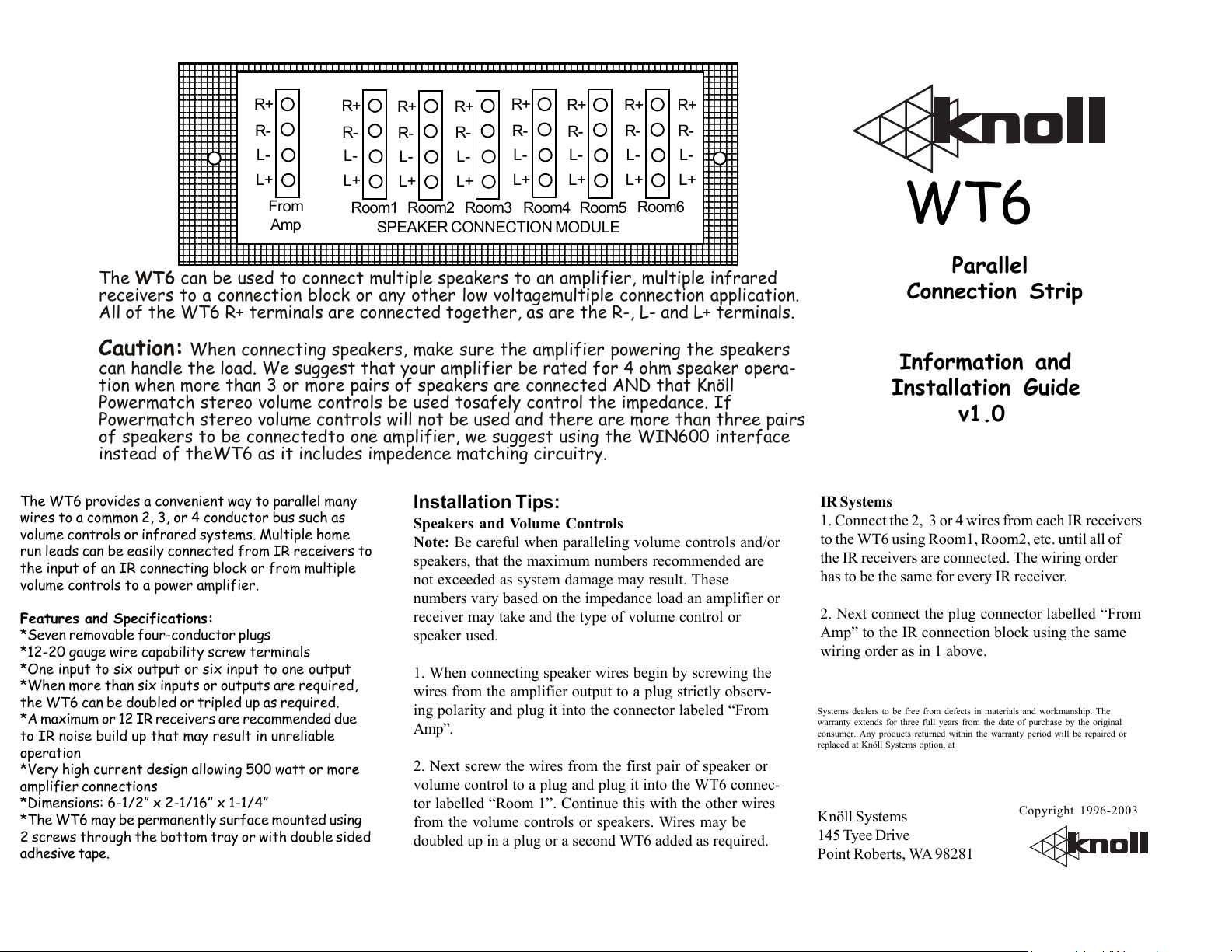
R+
R-
L-
L+
From
Amp
R+
R-
L-
L+
Room1
R+
R-
L-
L+
Room2
R+
R-
L-
L+
SPEAKER CONNECTION MODULE
R+
R-
L-
L+
R+
R-
L-
L+
Room3 Room4 Room5
R+
R-
L-
L+
Room6
R+
R-
L-
L+
The WT6 can be used to connect multiple speakers to an amplifier, multiple infrared
receivers to a connection block or any other low voltagemultiple connection application.
All of the WT6 R+ terminals are connected together, as are the R-, L- and L+ terminals.
WT6
Parallel
Connection Strip
Caution: When connecting speakers, make sure the amplifier powering the speakers
can handle the load. We suggest that your amplifier be rated for 4 ohm speaker operation when more than 3 or more pairs of speakers are connected AND that Knöll
Powermatch stereo volume controls be used tosafely control the impedance. If
Powermatch stereo volume controls will not be used and there are more than three pairs
of speakers to be connectedto one amplifier, we suggest using the WIN600 interface
instead of theWT6 as it includes impedence matching circuitry.
The WT6 provides a convenient way to parallel many
wires to a common 2, 3, or 4 conductor bus such as
volume controls or infrared systems. Multiple home
run leads can be easily connected from IR receivers to
the input of an IR connecting block or from multiple
volume controls to a power amplifier.
Features and Specifications:
*Seven removable four-conductor plugs
*12-20 gauge wire capability screw terminals
*One input to six output or six input to one output
*When more than six inputs or outputs are required,
the WT6 can be doubled or tripled up as required.
*A maximum or 12 IR receivers are recommended due
to IR noise build up that may result in unreliable
operation
*Very high current design allowing 500 watt or more
amplifier connections
*Dimensions: 6-1/2” x 2-1/16” x 1-1/4”
*The WT6 may be permanently surface mounted using
2 screws through the bottom tray or with double sided
adhesive tape.
Installation Tips:
Speakers and Volume Controls
Note: Be careful when paralleling volume controls and/or
speakers, that the maximum numbers recommended are
not exceeded as system damage may result. These
numbers vary based on the impedance load an amplifier or
receiver may take and the type of volume control or
speaker used.
1. When connecting speaker wires begin by screwing the
wires from the amplifier output to a plug strictly observing polarity and plug it into the connector labeled “From
Amp”.
2. Next screw the wires from the first pair of speaker or
volume control to a plug and plug it into the WT6 connector labelled “Room 1”. Continue this with the other wires
from the volume controls or speakers. Wires may be
doubled up in a plug or a second WT6 added as required.
Information and
Installation Guide
v1.0
IR Systems
1. Connect the 2, 3 or 4 wires from each IR receivers
to the WT6 using Room1, Room2, etc. until all of
the IR receivers are connected. The wiring order
has to be the same for every IR receiver.
2. Next connect the plug connector labelled “From
Amp” to the IR connection block using the same
wiring order as in 1 above.
Warranty
Knöll Systems warrants its products sold in the USA by authorized Knöll
Systems dealers to be free from defects in materials and workmanship. The
warranty extends for three full years from the date of purchase by the original
consumer. Any products returned within the warranty period will be repaired or
replaced at Knöll Systems option, at no cost. Knöll Systems will not be responsible
for the actual cost of removal or reinstallation of the product, nor of any incidental
or consequential damages. Some states do not allow the exclusion or limitation of
incidental or consequential damages, so the above limitations may not apply to you.
This warranty gives you specific legal rights. You may have additional legal rights
that vary from state to state.
Knöll Systems
WT6
145 Tyee Drive
Point Roberts, WA 98281
Copyright 1996-2003
 Loading...