

Page 1
INFORMATION AND
INSTALLATION GUIDE
Congratulations for choosing the finest
screen activator available. To assure correct
installation and to realize the full potential
of this product, please read and follow these
instructions carefully. If you have questions
or comments, please don't hesitate to call
or write your dealer. Your Knöll dealer has
the experience needed to pinpoint any
problems that may exist and has easy
access to technical information from the
Knöll Systems factory.
The VS27 SCREEN ACTIVATOR is
designed to lower motorized video screens
and activate other relay based functions
(such as turn off fireplace or close curtains)
when a composite signal to the projector (or
any other TV or video monitor) is detected.
Extra remote control commands or
mechanical wall mounted switches are not
required to activate the screen. When the
composite video signal is turned off, the
VS27 turns off the screen relay power,
rolling the screen back up. There are no
user serviceable parts in the VS27.
SCREEN
VS27
VS27
ACTIVATOR
INSTALLATION TIPS:
1. Follow electrical & building code requirements in your area.
2. Install the VS27 near the projector or video source.
3. Connect the video source composite output to the VS27. Please
note the composite output does not have to be viewed to activate
the screen (can view RGB, component, S-Video, etc.)
4. If required connect the VS27 to the projector composite input.
5. Connect the screen relay and socket as shown below. The
connections of the screen relay should be performed by a qualified
electrician. The relay and socket are normally located in the
junction box inside ME screens. Sometimes depending on the
series of the screen motors, the black and red wires from the
screen are inverted, causing the screen to roll down when the
projector is turned off. If this occurs, rewire the relay socket, with
the red wire to terminal 3 and the black wire to terminal 2.
6. Run a 16-22 gauge wire pair from the screen junction box to
the VS27. Fasten the relay socket inside the screen j-box. The
SCREEN RELAY jack provides constant 12VDC power to activate
the screen or other relays. When the video signal is turned off, so
is the 12VDC power for the relay(s).
7. After completing the above, plug in the PS09 power supply and
verify that the system is working.
NOTE: Connect PS09 to a
continuous 120VAC supply
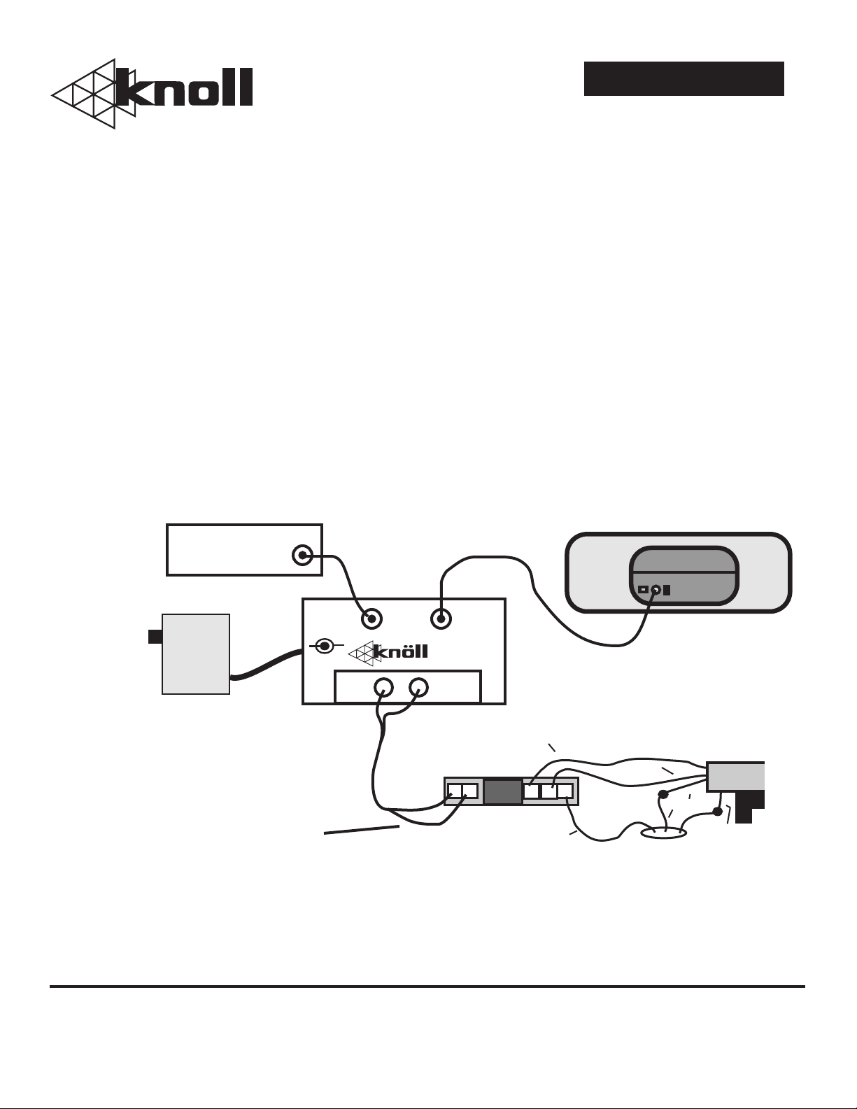
Fig 1
Video Source
IN
PS09
POWER
SUPPLY
Either wire can connect
to terminals 1 and 5
WARRANTY:
Knöll Systems warrants its products to be free from defects in materials and
workmanship. This warranty extends for one full year from the date of purchase
by the consumer. Any products returned freight pre-paid to Knöll systems and
found to be defective by Knöll Systems within the warranty period will be
repaired or replaced at Knöll Systems option, at no charge.
Knöll Systems
tel. (604) 272-4555
fax. (604) 272-5595
12VDC
-
+
In America:
1
45 Tyee Drive
Point Roberts, WA 98281
VIDEO
LOOP
VS27
BLACK
OMRON SCREEN RELAY
1
5
Note: Use connectors on white and green screen wires
Knöll Systems will not be responsible for the actual cost of installation or
removal of the product, nor for any incidental or consequential damages.
Some states do not allow the exclusion or limitation of incidental or
consequential damages, so the above limitation or exclusion may not apply to
you. This warranty gives you specific legal rights. You may have additional
rights which vary from state to state.
v
3
2
BLACK
Projector
NOTE: If screen goes up
when it should go down move
red wire from screen to relay
terminal 3 and black wire to
terminal 2.
v
ME
SCREEN
v
v
GREEN
TO GND
RED
4
v
In Canada:
11791 Machrina Way, #120
Richmond, B.C. V7A 4V3
120VAC
WHITE
v
08/98
 Loading...