

Page 1

Operation: Knoll volume controls are very easy to use. The VS150im
Peak RMS Power Rating
150-watts per channel
Continuous RMS Power
75-watts per channel
Frequency Response
20 to 20,000 Hz
Mounting Depth
2.25" (5.7cm)
Electrical Junction Box
Fits single gang
Speaker Impedance
4-16 ohms (single or multiple
speakers)
Connection
Detachable screw terminals
has a total of 12 different volume settings including fully off.
To increase the volume (in this room only), slide the volume control
knob upwards. To lower the volume, slide the volume control knob
downwards.
To set the correct amplifier or receiver volume setting, we suggest
that you turn the Knoll room volume control in one room to maximum.
Adjust the amplifier or receiver volume to the loudest comfortable
setting you will use and no further or louder. This way the Knoll
volume control has the most usable settings. If the amp volume
control was set louder, the Knoll volume control would have to be
turned down to be back at a comfortable level with less overall volume
positions available.
Warranty
Knoll Systems warrants the VS150im sold in the USA and Canada by authorized
Knoll dealers to be free of defects in materials and workmanship. This warranty
extends for three full years from the date of purchase by the original consumer.
Any products returned to Knoll Systems and found to be defective by Knoll
Systems within the warranty period will be repaired or replaced at Knoll
Systems option, at no charge. Knoll Systems will not be responsible for the
actual cost of installation or removal of the product, nor for any incidental or
consequential damages. Some states do not allow the exclusion or limitation of
incidental or consequential damages, so the above limitation may not apply to
you. This warranty gives you specific legal rights. You may have additional
legal rights that vary from state-to-state.
Specifications
Knoll Systems
145 Tyee Drive Point Roberts, WA 98281 USA
14-7163 Vantage Way, Delta BC V4G 1N1 Canada
Tel: (604) 940-1689, fax (855) 734-3363
www.knollsystems.com
VS150im
Impedance Matching Volume Control
Installation Instructions v1.3
Warning: To be installed and/or used in accordance with appropriate
electrical codes and regulations.
Caution: Do not install these keypads in an electrical junction box
with 110V or higher unless an approved barrier separates the high and
low voltage sections.
Description: The Knoll VS150im is a twelve-position in-wall
mountable stereo speaker volume control with impedance matching
capability. From one to sixteen pairs of speakers can be safely driven
from one stereo amplifier using an equal number of VS150im’s.
Separate impedance matching components are not required. The Knoll
WT6 one stereo input to six stereo output connection strip is available
to neaten the wiring of larger systems.
A rotary switch version is available, model VC150im.
Basic System Layout and Pre-Wiring: A stereo amplifier controls
multiple pairs of speakers. Decide where the speakers and volume
controls will be placed in the various rooms. When wiring always leave
an extra couple of feet of wire at both ends so installation of the
speakers and volume controls is quick and easy. Up to 16 pairs of 8ohm speakers can be safely connected to one amplifier. (8 pairs of 4ohm speakers).
Run a fire-rated two-conductor speaker wire (14-18 gauge wire) from
each speaker to the volume control location in each room. Next, run a
four-conductor speaker wire from the volume control to the amplifier
location. Ideally each run back to the amplifier is a home run, but
wires can be daisy chained from room to room. If you plan to daisy
chain the wiring we suggest using larger 14-gauge wire. If 2 pairs of
speakers are being controlled by 1 volume control, wire the 2 pairs in
series if they are 4 or 6-ohms and parallel if they are 8 or 16-ohms.
Our web site has information on how to wire in series and parallel.
Warning: Never attempt to make the final combined speaker
impedance less than 4-ohms as this may cause safety issues.
To make final trim-out quicker, the detachable connectors with the
VS150im can be added to the wires now. They are available in bulk
packs without the volume controls from Knoll.
To tidy up the installation, use Knoll’s WT6 seven position wire
connection strip at the amplifier. Two or more may be required for
some installations.
Page 2
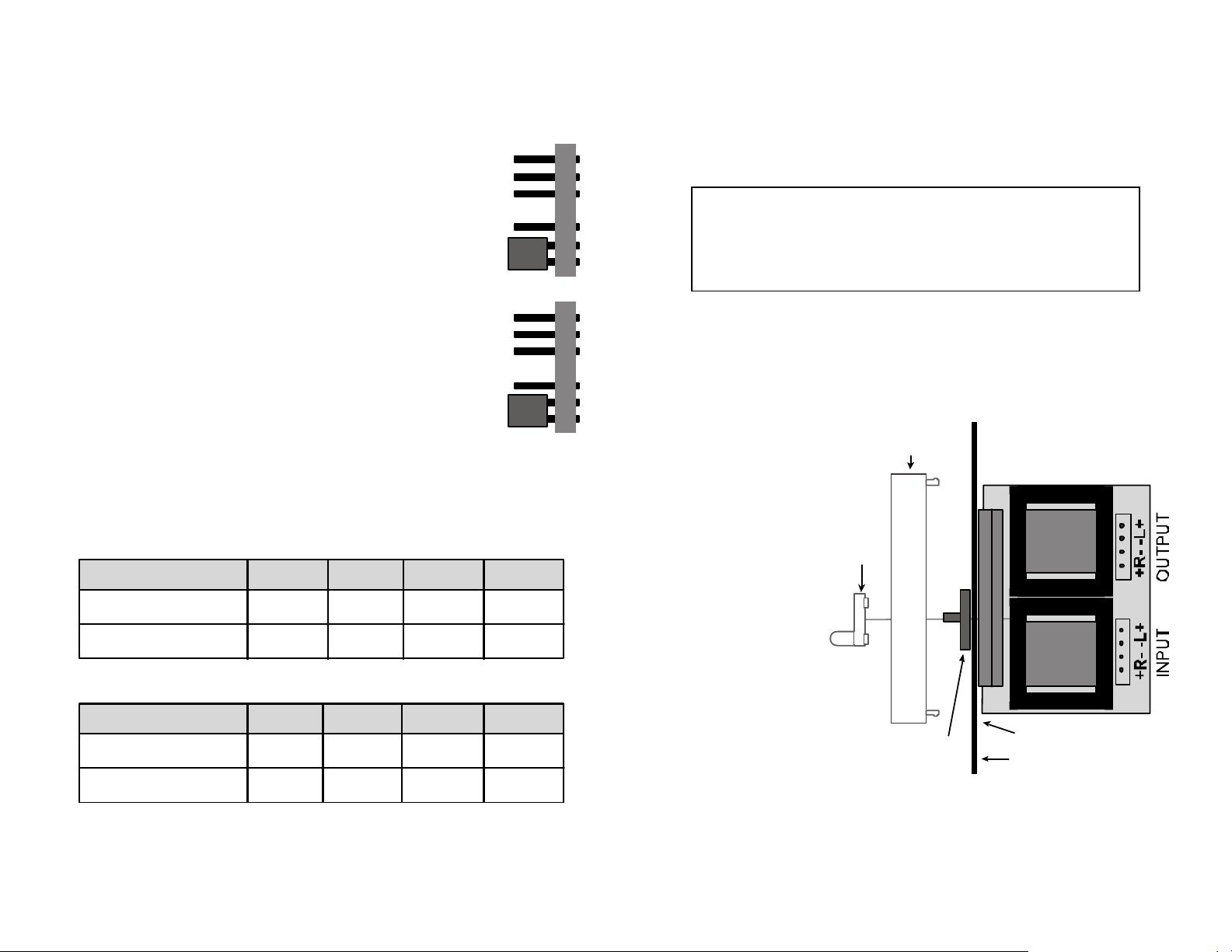
Setting the impedance matching jumpers:
Jumper setting
X1 X2
X4
X8
4 Ohm speakers
8 Ohm speakers
don’t 1 pair 2 pair 3-4 pair
1 pair 2 pair
3-4 pair 5-8 pair
When using amps or receivers with 8 ohm capacity
Jumper setting
X1 X2
X4
X8
4 Ohm speakers
8 Ohm speakers
1 pair 2 pair 3-4 pair
2 pair
3-4 pair 5-8 pair
When using amps or receivers with 4 ohm capacity
5-8 pair
9-16 pr
1X
2X
4X
8X
1X
2X
4X
8X
VS150im
Metal plate
Plastic
Plate
Control
shaft
Knob
bottom tab
Each of the VS150im volume controls needs to have the jumpers
correctly set. The two jumpers are located on the rear side of the
volume control. Both channels on all volume controls in this system
should be set to the same jumper setting.
The jumper setting is determined by three factors:
1. The speaker impedance (all the speakers in
this system should have the same
impedance).
2. The number of volume controls connected to
one stereo amplifier.
3. The minimum speaker load impedance the
amplifier can handle.
In the left illustration both jumpers are shown set in
the X1 position. The top jumper set is for the left
speaker and the bottom set is for the right speaker.
Ideally, all volume controls in this system
should have their jumpers set to the same
correct position. 4 and 8 ohm speakers can safely
be combined in a system. Use the 4 ohm settings.
The jumper needs to be pushed on as far as it goes.
To determine the correct jumper or shunt position, use the
chart below.
As an example, if the amplifier has 4-ohm capability with 7 pairs of 8
ohm speakers to be installed, set all VS150im jumpers to X4.
Connection and trim-out: Remove the eight position speaker
connector. Remove about ¼” of insulation from the ends of all wires
connected to the volume control and twist the exposed strands. The
stereo amplifier or receiver outputs (left and right) are connected to
the VS150im connector portion labeled “INPUT” on the volume control.
Be very careful to observe the correct polarity. The VS150im uses
independent floating grounds so bridged amplifiers can be used safely.
Warning: The VS150im is rated for use with
maximum 150-watt per channel amplifiers.
DO NOT use higher-powered amplifiers with
this product for safety reasons.
Wire from the amplifier speaker terminals is always wired in parallel to
all VS150im volume controls. To make the installation look neat and
tidy, we suggest using one or more WT6 connection strips. When
connecting to the amp make sure its power is switched off. Again
strictly observe wiring polarity.
Connect the wires
from the stereo
speakers to the
connector portion
labeled “OUTPUT” on
the volume control.
Again series and
parallel speaker
wiring is acceptable
so that the
impedance the
volume control sees
is between 4 and 8
ohms. Be sure to
strictly observe
polarity, as incorrect
polarity will result in
poor bass
performance.
When installing the
volume control into the wall, we suggest moving any inside wall
fixtures such as vapor barriers away from the autotransformers if
possible.
 Loading...