

Knoll VOC120 Installation Guide
Operation: Knoll volume controls are very easy to use. The V0C120
has a total of 12 different volume settings including fully off.
To increase the volume (in this room only), turn the volume control
knob clockwise. To lower the volume, turn the volume control knob
counterclockwise.
To set the correct amplifier or receiver volume setting we suggest that
you turn the Knoll room volume control in one room to maximum.
Adjust the amplifier or receiver volume to the loudest comfortable
setting you will use and no further or louder. In this way the Knoll
volume control has the most usable settings. If the amp volume
control was set louder, the Knoll volume control would have to be
turned down to be back at a comfortable level with less overall volume
positions available.
Warranty
Knoll Systems warrants the V0C120 sold in the USA and Canada by authorized
Knoll dealers to be free of defects in materials and workmanship. This warranty
extends for three full years from the date of purchase by the original consumer.
Any products returned to Knoll Systems and found to be defective by Knoll
Systems within the warranty period will be repaired or replaced at Knoll
Systems option, at no charge. Knoll Systems will not be responsible for the
actual cost of installation or removal of the product, nor for any incidental or
consequential damages. Some states do not allow the exclusion or limitation of
incidental or consequential damages, so the above limitation may not apply to
you. This warranty gives you specific legal rights. You may have additional
legal rights that vary from state-to-state.
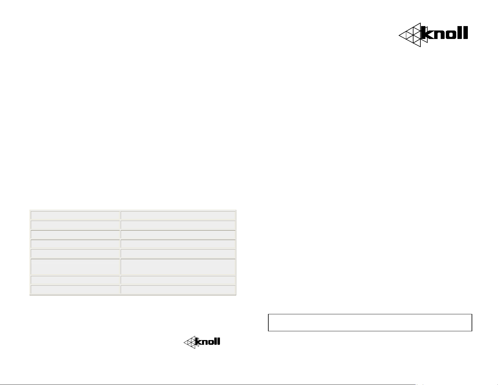
Specifications
Peak RMS Power Rating 120 watts power handling
Continuous RMS Power 60 watts per channel
Frequency Response 20 to 20,000 Hz
Mounting Depth 4-3/8” (111 mm)
Dimensions 3-3/4” w x 5” (95 x 127 mm)
Speaker Impedance
Connection Detachable screw terminals
Colors and Styles Order as white or gray
Knoll Systems
145 Tyee Drive Point Roberts, WA 98281
12140 Horseshoe Way, Richmond, BC V7A 4V4
Tel: (604) 272 4555, fax (604) 272 5595
www.knollsystems.com
4-16 ohms (single or multiple
speakers)
VOC120
Outdoor Volume Control
Installation Instructions v1.2
Warning: To be installed and/or used in accordance with appropriate
electrical codes and regulations.
Caution: Do not install these keypads in an electrical junction box
with 110V or higher unless an approved barrier separates the high and
low voltage sections.
Description: The Knoll V0C120 is designed to provide volume control
for outdoor or wet locations and can be mounted on an exterior wall or
virtually any hard, flat surface. It is designed to be mounted directly
on 3/4 inch PVC conduit. The V0C120 provides superior protection
against moisture from rain, sauna, etc. or wherever moisture can be a
problem. The VOC120 adjusts volume level by attenuating the
amplifier signal output of the VOC120 to the speakers.
VOC120’s use impedance matching autoformers and are available in
white and gray colors.
Basic System Layout and Pre-Wiring: A stereo amplifier controls
one or multiple pairs of speakers. Decide where the speakers and
volume controls will be placed. For longest life the volume controls and
speakers should be out of direct rain and sunlight. When wiring always
leave an extra couple of feet of wire at both ends so installation of the
speakers and volume controls is quick and easy. Up to 16 pairs of 8ohm speakers can be safely connected to one amplifier (8 pairs of 4ohm speakers).
Run a two-conductor speaker wire (14-18 gauge wire) from each
speaker to the volume control location (inside the conduit, of course).
Next, run a four-conductor speaker wire from the volume control to
the amplifier location. Ideally each run back to the amplifier is a home
run, but wires can be daisy chained from room to room. If you plan to
daisy chain the wiring we suggest using larger 14-gauge wire. If 2
pairs of speakers are being controlled by 1 volume control, wire the 2
pairs in series if they are 4 or 6-ohms and parallel if they are 8 or 16ohms. Our web site has information on how to wire in series and
parallel.
Warning: Never attempt to make the final combined speaker
impedance less than 4-ohms as this may cause safety issues.
To make final trim-out quicker, the green detachable connectors with
the VOC120 can be added to the wires now. They are available in bulk
packs (without the volume controls) from Knoll.
To tidy up the installation, use Knoll’s WT6 seven position wire
connection strip at the amplifier location. Two or more may be
required for some installations.
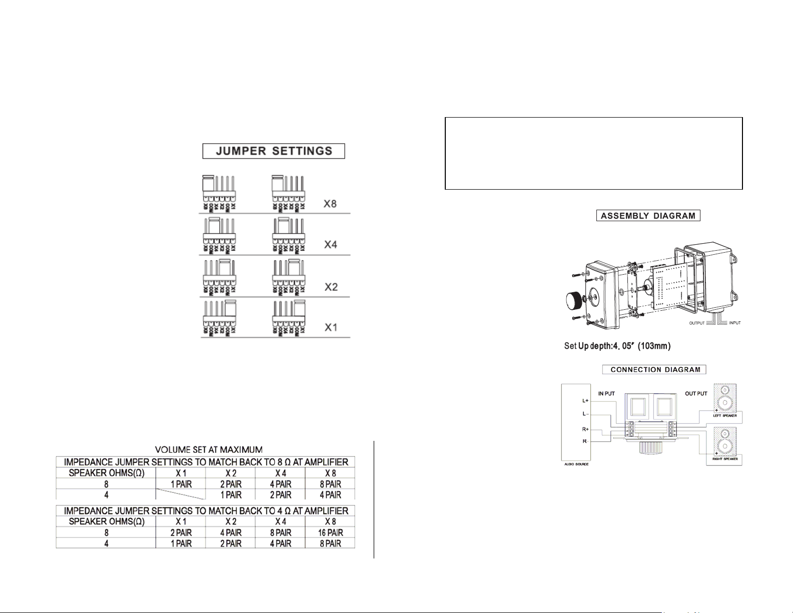
Setting the impedance matching jumpers:
The jumpers must be set in a position that correctly multiplies the
impedance of the system to a level that is equal to or greater than the
impedance of the amplifier.
The jumper setting is
determined by three factors:
1. The speaker
impedance (all the
speakers in this
system should have
the same
impedance).
2. The number of
volume controls
connected to one
stereo amplifier.
3. The minimum
speaker load
impedance the
amplifier can handle.
Make sure that your amplifier has adequate wattage for the number of
speakers. Watts per channel divided by the number of pairs should
equal or exceed the individual speaker’s minimum wattage
requirements. You must use a Knoll volume control for each pair of the
speakers. Every jumper setting should be set on the same setting
throughout the system.
To determine the correct jumper position, use the chart below.
As an example, if the amplifier has 4-ohm capability with 7 pairs of 8ohm speakers to be installed, set all V0C120 jumpers to X4.
Connection and trim-out: Remove about 1/4 ” of insulation from the
ends of all wires connected to the volume control and twist the
exposed strands. The removable connectors accept up to 14-guage
wire. Loosen the set screws on the volume control.
The V0C120 is rated for use with maximum
150-watt per channel amplifiers. DO NOT use
higher-powered amplifiers with this product
for safety reasons.
Wire from the amplifier
speaker terminals is
always wired in parallel
to all V0C120 volume
controls. To make the
installation look neat
and tidy, we suggest
using one or more WT6
connection strips. When
connecting to the amp
make sure its power is
switched off. Again
strictly observe wiring
polarity.
Connect the leads from
Amplifier to the set
screws on the volume
control labeled Input,
with the LEFT L (+)
and L (-) and RIGHT R
(+) and R (-) wires.
Insert in the
appropriately marked
opening. Tighten
screws firmly. Connect Speaker wires to the set screws on the
volume control labeled Output, observing + (positive) and –
(negative) polarity of left and right speaker.
Install the completed assembly in the junction box. Insert carefully to
avoid excessive strain on the set screws. If necessary, pre-dress the
wires for the easiest and strain free mounting.
 Loading...