

Page 1
VC75pm Stereo impedance matching volume control
Congratulations for choosing the finest stereo volume control available. To assure
correct installation and realize the full potential of this new volume control, please
read and follow these instructions carefully. If you have questions or comments,
please don't hesitate to call or write your Knöll dealer.
Knöll volume controls are designed to fit standard electrical junction boxes (Jboxes). Standard plate colors are white, ivory and almond. The VC75pm has a power
capacity of 75 watts RMS per channel with 125 watt peaks. Speakers can be 4-16
ohms. The VC75pm features floating independent grounds so bridged amplifiers can
be safely used. For best results when connecting two or more VC75pm volume
controls to one amplifier or receiver, use a Knöll transformer WT6 interface. Knöll
also makes transformer free stereo volume controls and impedence matching models.
Ask your dealer for details.
Installation Tips: (be sure to adjust the switch #8 below)
1. Follow all electrical and building code requirements in your area.
2. The VC75pm can be installed in an electrical junction box, but it is not required.
3. Never install the VC75pm in the same electrical junction box as high-voltage
equipment (75+ volt) unless an approved barrier separates high from low voltage
equipment.
4. Speaker wire can be solid or stranded. Suggested minimum wire size is 16 gauge
and 14 gauge for runs longer than 30' (10m).
5. Wire both left and right speaker outputs from the amplifier, receiver or interface
to the VC75pm inputs removing about 1/4” of wire insulation.
6. Proper polarity is essential to achieve best speaker sound quality with maximum
output. Be careful to wire the + or positive terminals of the amplifier, interface,
VC75pm volume control and speakers together. Never connect left and right channel
wires of the positive OR ground as amplifier damage may result. The - or negative
terminals of the amplifier, volume control and speakers must be wired as shown in
the diagram.
7. Wire the VC75pm outputs to the corresponding speaker terminals as indicated
on the VC75pm connector.
8. *** Set the impedance matching switch *** as shown in the setting chart.
9. Carefully inspect for speaker wire strands.
10. Install the completed assembly in the wall.
USA and Canada Warranty
Knoll Systems warrants its VC75pm sold in the USA and Canada by authorized
Knoll Systems dealers to be free of defects in materials and workmanship.
This warranty extends for two years from the date of purchase by the original
consumer. Any VC75pm returned to and found to defective by Knöll Systems
within the warranty period will be repaired or replaced at Knoll Systems option
at no charge. Knöll Systems will not be responsible for the actual
cost of installation or removal of the product, nor for any incidental or
consequential damages. Some states do not allow the exclusion or
limitation of incidental or consequential damages, so the above limitation
may not apply to you. This warranty gives you specific legal rights.You
may have additional legal rights that vary from state to state.
Adjust switch settings to match
back to 4 ohms at amplifier
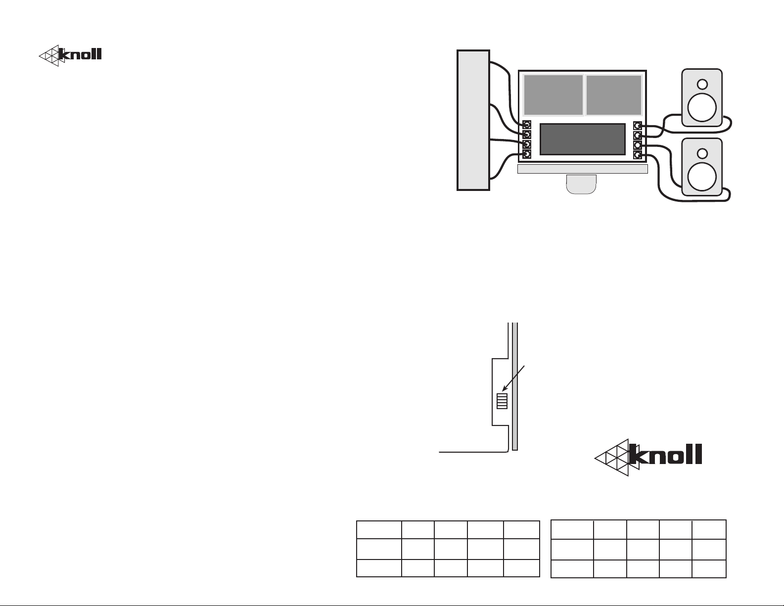
CONNECTION
DIAGRAM
VC75pm
SPEAKER OUTPUTS
+ L - - R +
STEREO AMPLIFIER OR
RECEIVER OR INTERFACE
Suggested minimum 16 gauge speaker wire. For
runs longer than 30 feet (10m) use 14 gauge wire.
Impedance Matching Switch Settings
(Remove knob and cover plate)
Using chart below, adjust
X2
X4
X8
X16
impedance matching switch
for optimum setting. If using
one pair of speakers per
amplifer use X2 setting.
Shown in X8 setting.
Adjust switch settings to match
back to 8 ohms at amplifier
L
+
-
R
+
-
Knoll Systems
145 Tyee Drive, Point Roberts, WA 98281
11791 Machrina Way, #210 Richmond, BC V7A 4V3
Speaker 2X 4X 8X 16X
8 ohms 4 pair 8 pair 16 pair 32 pair
4 ohms 2 pair 4 pair 8 pair 16 pair
Speaker 2X 4X 8X 16X
8 ohms 2 pair 4 pair 8 pair 16 pair
4 ohms 1 pair 2 pair 4 pair 8 pair
 Loading...