

Page 1
VC220pi
Digital Volume Control
Installation Instructions
Warning: To be installed and/or used in accordance with appropriate electrical
codes and regulations.
Caution: Do not install these keypads in an electrical junction box with 110V or
higher unless an approved barrier separates the high and low voltage sections.
Description: The Knöll VC220pi digital volume control attenuates stereo speaker signals
in 17 steps. It contains Powermatch circuitry allowing connection of up to eight
VC220pis to a receiver. A non Powermatch version, model VC220 is available. The
VC220pi includes mute and start-up functions. The VC220pi is controlled with a VC201,
a RB8 remote control (requires a VC201i keypad) or an external controller such as the
VCI-28 interface. Up to three VC201 (not VC201i) keypads can be connected (daisy
chained) to a VC220pi. The VC201i keypad contains an internal infrared receiver (no
extra wiring is necessary) to control the stereo and other systems. The VC220pi requires
a 12VDC power supply, is usually wall-mounted and works best if mounted vertically.
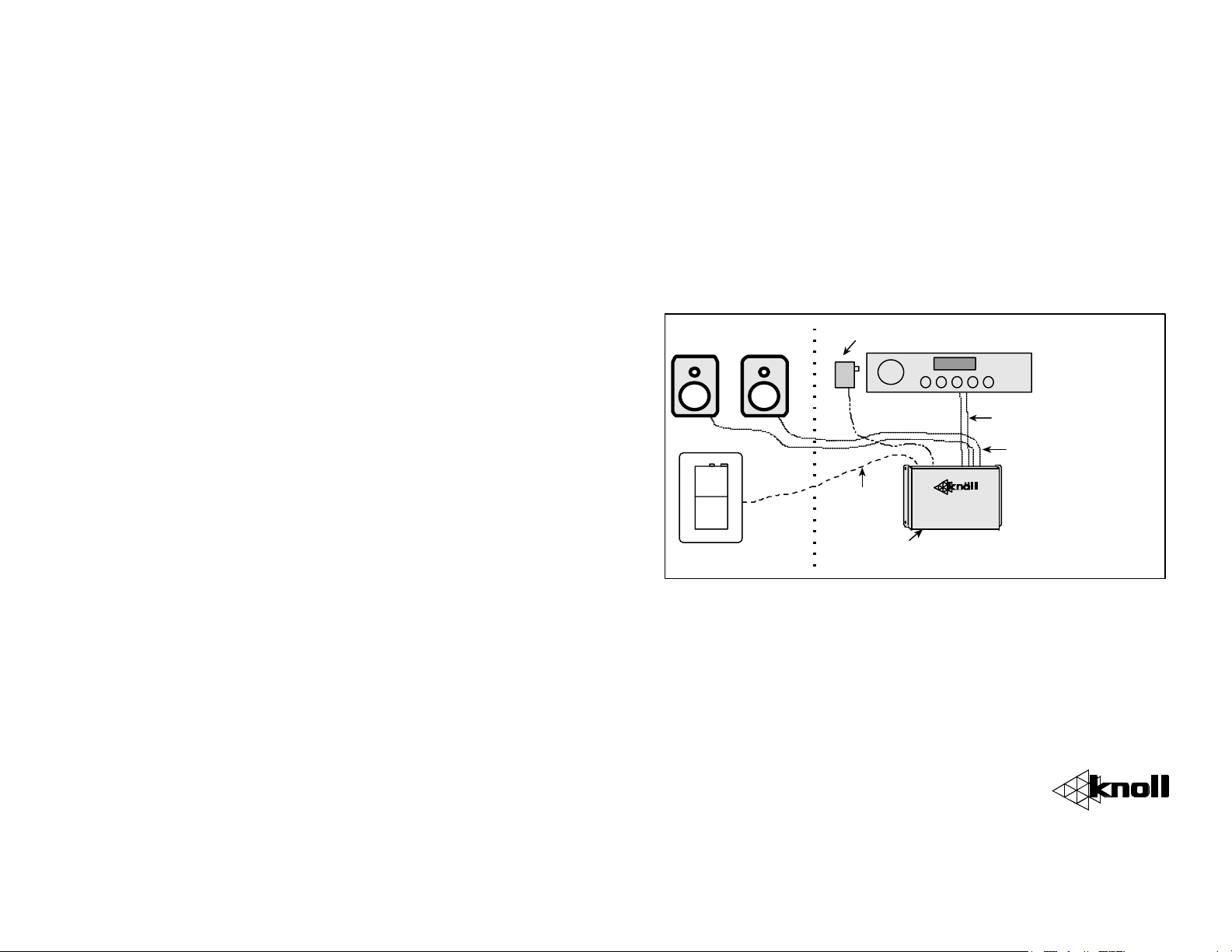
Basic System Layout and Pre-Wiring: See “Typical Wiring Diagram” on the back
page. The VC220pi makes a noticeable “click” sound when changing volumes. We
suggest mounting it in a low voltage panel, electrical room, closet, etc. From one to eight
VC220pi’s can be connected to a single amp or receiver (that has 4 ohm capability). Only
one VC201i can be connected to a single VC220pi. The VC200 keypad does not work
with the VC220pi.
Use the standard T568A wiring practices to run a cat 5 or cat 3 wire from the keypad or
controller to the VC220pi. If more than one keypad controls a single VC220pi daisy
chain the wire from keypad to keypad. If the VC220pi(s) are not located next to the
stereo, run a single eight-conductor cat 3 or cat 5-wire run from the stereo to the
VC220pi(s) for the power supply, the infrared system and future upgrades such as paging
override.
From each VC220pi run a fire rated two-conductor speaker wire to each speaker. To
save time and money, most installers run a four-conductor speaker wire from the
VC220pi to the closest appropriate speaker and then run a short two-conductor speaker
wire to the other speaker. If there is more than one pair of speakers connected to a single
VC220pi, the speakers can be wired in series or parallel whichever makes the impedance
closest to 4 or 8 ohms. Do not attempt to make the final combined speaker impedance
less than 4 ohms.
If the VC220pi(s) are not
(or two two-conductor) 14-18 gauge speaker wire from the stereo to the VC220pi(s).
located next to the stereo, run a single fire rated four-conductor
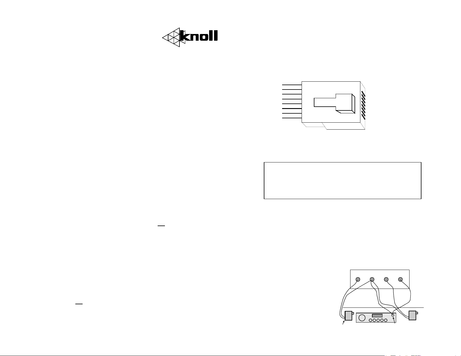
Connecting VC201/VC201i keypads to VC220pi controllers:
Use a single cat5 wire using all eight conductors (usually run inside a wall). Always use
standard T568A Cat 5 wiring practices (shown below). Use the correct wire pairs.
Polarity is VERY important! The stereo signal is not routed to the keypad, just the digital
control signals. Signals from an infrared receiver (if used) are routed down the same Cat
5 wire. If more than one keypad (VC201, not VC201i) is to be connected to a VC220pi
controller, the wires to the keypads are paralleled.
VC201i keypads are connected
brown 8
white/brown 7
orange 6
white/blue 5
white/orange 3
blue 4
green 2
white/green 1
to VC220pi controllers, the
same as other keypads, the
only difference is extra power
supply and IR emitter wiring
are required (see Infrared
connection diagram below).
Connection to Stereo Equipment: Remove the VC220pi eight-position speaker
connector. The stereo amplifier or receiver outputs (left and right) are connected to the
VC220pi connector labeled “TO AMP”. Be very careful to observe the correct polarity.
The VC220pi uses independent floating grounds so bridged amplifiers can be used safely.
***The VC220pi is rated for use with maximum
120 watt per channel amplifiers. DO NOT use
higher-powered amplifiers with this product
for safety reasons.***
Up to eight VC220pi controllers can be connected to a single amplifier or receiver if it
rated for 4-ohm use. If the amplifier or receiver is rated for 8-ohm use, up to three
VC220pi controllers can be connected. Wire from the amplifier speaker terminals are
always wired in parallel to the VC220pi controllers “TO AMP” terminals either by
stripping and soldering, using a speaker wire paralleling board (our model WT6), or daisy
chaining from one VC220pi connector to the next VC220pi connector etc. Connect all
VC220pi’s to amplifier speaker A or speaker B terminals, but not both. Wire the
VC220pi connectors labeled “SPEAKER” directly to the correct speakers, again strictly
observing polarity.
Power Requirements: The VC220pi
needs a 12vdc power supply. The
VC220pi controller also supplies
power to the keypads. A maximum of
60mA is needed for each VC220pi. If
possible, connect the 12vdc power
supply to the switched outlet on the
rear of the amplifier or receiver. This
wiring causes the VC220pi to reset to
its selectable “boot up” every time the
VC220/VC220pm
POWER
+12V G 12V SIG
-
+
12VDC power supply plugged
into stereo switched outlet
Stereo
INFRARED
Infrared
emitter(s)
+
-
12VDC power supply
plugged into power
full time
Page 2
receiver or amplifier is turned on. The plug on the end of the 12vdc power supply needs
to be cut off and discarded. The wire is stripped off and connected to the VC220pi
terminal labeled +12V and G (ground is the negative terminal). To connect more than one
VC220pi to a receiver, daisy chain the 12vdc power supply wires to the other VC220pi
controllers.
If one 12vdc power supply powers both the VC220pi and the VC201i infrared receiver,
wire the unswitched 12VDC supply to the “POWER” +12V and G terminals on the
VC220pi, then run a jumper wire from the “POWER” +12V to the “INFRARED” 12V
terminals.
Installer Selectable “BOOT UP”: The VC220pi allows the installer to select how the
volume control “boots up” when it first receives 12vdc power. If this feature is required,
be sure to plug the 12vdc power supply to the switched AC outlet on the rear of the
receiver or amplifier. The VC220pi default is start muted when the 12VDC power is first
turned on.
•To always start muted and in the lowest volume step (off) make sure the right side shunt
on the VC220pi controller labeled "start muted" is in place.
•To always start up in a quiet position #6 (of 17). Remove the right shunt labeled "start
muted" and make sure the left shunt labeled "#12 #6" is in place.
•To always start up in a louder position #12 (of 17). Remove the right shunt labeled "start
muted" and remove the left shunt labeled "#12 #6".
•To restore the boot up defaults, replace the appropriate shunts.
Operation: The Knöll digital volume control is very easy to use. It has a total of 17
different volume settings. Volume settings only affect the room that they are in. After the
stereo is turned on, you may or may not have sound depending on how the system was
set up during installation.
To increase the volume (in this room only), push the rocker button up. Hold the button up
continuously and the volume will increase until maximum. To lower the volume, push
the rocker button down. Hold the button down continuously and the volume will decrease
until it mutes.
At any time firmly press the center of the switch to mute the volume. To restore the
volume press the rocker button up or down.
The RB8 remote control source buttons do not work on the VC201/VC220pi as it has no
source selection capabilities.
If infrared emitters where installed other (source) remote controls aimed at the VC201i
keypads will control the source components.
On VC201 keypads the lower led indicates that power to the system has been switched
on. The six side leds show the relative volume. When in mute (center of rocker has been
pushed) one of the side leds blinks. To restore the volume press the rocker button up or
down.
Note: If the stereo is on and the Knöll digital volume control has lost power, it defaults to
position #12.
Warranty
Knöll Systems warrants its products sold in the USA and Canada by authorized Knöll
dealers to be free of defects in materials and workmanship. This warranty extends for two
full years from the date of purchase by the original consumer. Any products returned to
Knöll Systems and found to be defective by Knöll Systems within the warranty period
will be repaired or replaced at Knöll Systems option, at no charge. Knöll Systems will not
be responsible for the actual cost of installation or removal of the product, nor for any
incidental or consequential damages. Some states do not allow the exclusion or limitation
of incidental or consequential damages, so the above limitation may not apply to you.
This warranty gives you specific legal rights. You may have additional legal rights that
vary from state to state.
The VC200, VC201 and VC220pi have no user replaceable parts.
12vdc power su pply plug ged
Speakers 4-16 oh m
into s tereo swi tch ed o utlet
Typical
Wiring
Diagram
L R
VC200
8 condu cto r
cat 3 or cat 5
wire
Start mu te and
boot-up l evel
Room 1 Room with stereo
Knoll Systems
145 Tyee Drive Point Roberts, WA 98281
11791 Machrina Way, #120 Richmond BC V7A 4V3
tel (604) 272 4555, fax (604) 272 5595
www.knollsystems.com
Made in Canada
VC220pi 1999-2000 Knoll Systems All Rights Reserved
shun ts
Stereo
systems
Digital Speaker
Vol ume Contr ol
VC 22 0p m
2 cond uctor sp eaker wi res
from a mp t o VC 200pm
2 conductor s peaker wi res
from VC2 00pm to spea ke rs
Note:
VC220p m c an b e
located in a remote
closet, electrica l room etc.
Note:
Speaker wires from
amp to VC220pm and for
12Vdc are loo ped t o
multiple VC220pm’s
 Loading...