

Page 1
Connecting Infrared: Infrared receivers and emitters can be
connected on either side. Please note 12 volt power for the infrared is
supplied only on the HDMI send or HDMI receive that has the PS1205
power supply connected. Emitters should be connected using a Knoll
infrared connection block (IR55) or using an inline (series) 220 ohm
dropping resistor to avoid early emitter failure.
HDMI Balun Specifications:
Models and Dimensions
UDR-HDMI (in-wall Decora™ version): 4.1"h x 1.4" w x 2.0"d.
UDS-HDMI (in-wall Decora™ version): 4.1"h x 1.4" w x 2.0"d.
UR-HDMI (black enclosure): 1.1"h x 2.6"w x 2.8"d (28 x 66 x 71 mm).
US-HDMI (black enclosure): 1.1"h x 2.6"w x 2.8"d (28 x 66 x 71 mm).
Inputs and Outputs:
Send Unit: One HDMI input jack, two RJ-45 out-jacks, one-DC
power input, one three position Infrared connector.
Receive Unit: One HDMI output jack, two RJ-45 in-jacks, one-DC
power input, one three position Infrared connector.
Power:
Send Unit: 12 VDC 500mA.
Receive Unit: 12 VDC 500mA.
Warranty
Knoll Systems warrants its products sold in the USA and Canada by authorized
Knoll dealers to be free of defects in materials and workmanship. This warranty
extends for three full years from the date of purchase by the original consumer.
Any products returned to Knoll Systems and found to be defective by Knoll
Systems within the warranty period will be repaired or replaced at Knoll Systems
option, at no charge. Knoll Systems will not be responsible for the actual cost of
installation or removal of the product, nor for any incidental or consequential
damages. Some states do not allow the exclusion or limitation of incidental or
consequential damages, so the above limitation may not apply to you. This
warranty gives you specific legal rights. You may have additional legal rights
that vary from state to state.
Knoll HDMI baluns pass HDCP signals and does not manipulate
them in any way.
Knoll Systems www.knollsystems.com
145 Tyee Drive Point Roberts, WA 98281
12140 Horseshoe Way, Richmond BC V7A 4V5
Tel. (604) 272 4555, fax (604) 272 5595
Made in Canada Knoll Systems All Rights Reserved
UDR-HDMI Receiver
UDS-HDMI Sender
UR-HDMI Receiver
US-HDMI Sender
Installation Instructions v1.7
Warning: To be installed and/or used in accordance with
appropriate electrical codes and regulations. If you are not sure
about any part of these instructions, consult a qualified
electrician.
Caution: Do not install this product in an electrical junction box
with 110V or higher unless an approved barrier separates the
high and low voltage sections.
Introduction: Thank you for your purchase of a Knoll active
balun system. This system is specifically designed to send HDMI
and infrared signals safely down a two cat 5e or cat 6 wires up
to 115 feet (35 meters) without encountering signal degradation
problems (resolutions lower than 1080p will go further).
To install wires inside walls, in most jurisdictions require wires
to be minimum class 2 rated for safety. Almost all conventional
HDMI wires are unrated so they cannot legally be installed
inside walls. The most cost effective method to install a legal
HDMI inwall run is to use cat 5e wire and Knoll HDMI baluns.
Features:
Tabletop box design or Decora™ style available.
Will safely send 480i/p, 720p and 1080i/p signals.
PS1205 power supply can be connected on either the
send or receive side.
Mix and match decora style and tabletop style.
Infrared receivers and emitters can be connected on
either side
Page 2
Receive
Two
CAT 5
wires
PS1205
Send
Emitter
DLP-TV
Infrared Receiver
UR-HDMI
HDMI Re ceive Bal un
Power
12 VDC
HDMI
Output
Adjus t
CAT5 Wire
XA XB
Infared
US-HDMI
HDMI Se nd Balun
HDM I Input
CAT5 Wire
XAXB
Infared
HD Player
Powe r
1 2 VDC
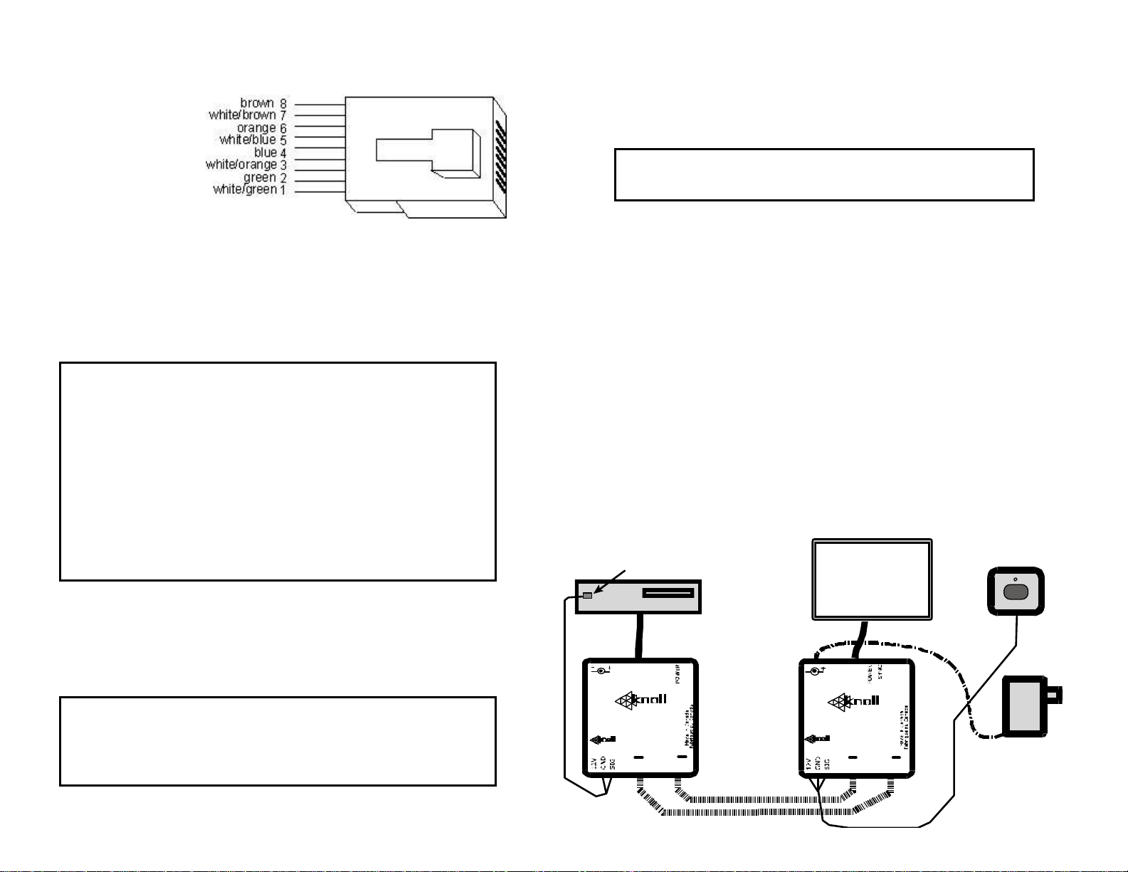
Wiring: A send
module (UDS-HDMI
or US-HDMI) needs
to be connected to a
Knoll receive module
(UDR-HDMI or URHDMI) to work
correctly. The send
and receive module
are connected using two cat 5e or cat 6 wires using all 8 conductors in
each. Connection is made with the RJ45 connector (RJ45 plug not
supplied). Always use standard 568-A cat 5 wiring practices (shown
above). Using the correct wire pairs and polarity is VERY important.
Make absolutely sure the XA port on the send unit is connected to the
XA port on the receive unit. Likewise the XB port on the send unit is
connected to the XB port on the receive unit. Both wires are needed.
Please note the maximum cat5e or cat6 wire length for reliable
operation of 1080p is 115 feet or 35 meters. Do not attempt
a longer length as it may not be reliable. For lower resolutions
such as 720p or 1080i the maximum length is 135 feet or 42
meters. Cat 5e and cat 6 wires should be as short as possible.
Never run the cat 5e or cat 6 wires near or along side high
voltage wires. If high voltage lines are near by cross the cat 5e
or cat 6 wires to them at 90 degree angles.
Never coil up cat 5e or cat 6 wires. This can increase the
inductance of the wire and may give an unreliable picture.
Connection to HDMI source equipment: Connect the UDS-HDMI or
US-HDMI HDMI connectors with as short as possible HDMI cord to the
source equipment. Less than 2 meters (6’) is best. The maximum
length the HDMI cables to the input and output combined is about 35’
(10 meters).
Make sure a good quality RJ45 8-8 crimper is used to
connect the RJ45 connector to the cat 5 wire. Poor crimping
and mismatched wires are the most frequent cause of
installation problems.
Power requirements: The Knoll HDMI balun system requires a single
PS1205 power supply connected to the send or receive unit.
Note: If the cat 5 wire length exceeds 70’ (21m) we strongly
suggest connecting the power supply to the receive side only.
Note: The HDMI decora style and enclosure style
Models can be mixed or matched as desired.
Connection to the Projector, TV or other components: Connect
short as possible HDMI cable from the receive balun to the projector,
TV or other component. The maximum length the HDMI cables to the
input and output combined is about 35’ (10 meters).
Setting the HDMI switch: There is a switch on the receive unit that
adjusts the Knoll HDMI balun system. In our testing experience we find
that a setting of 1 or 2 for anything below 5 metres setting 3 for 5 – 21
metres and 4 is best setting generally for all 1080p material from 22 29 metres (98.43 ft), usually a setting of 6 or 7 for distances above 30
– 35 metres (115 ft). Feel free to experiment with other settings. To
see this effect turn a 1080p image on and try adjusting the switch.
Lower resolution images (480i/p, 720p, 1080i) are not affected as
much by changing the settings.
If problems are experienced with this product, please call our tech line
for help at 1 800 566 5579.
This product may contain lead that some states have determined is
harmful. Wash you hands after touching this product.
Decora™ is a trademark of Leviton.
 Loading...