

Page 1
UDR-SVID S-video and Infrared Receiver
UR-SVID S-video and Infrared Receiver
UDS-SVID S-video and Infrared Sender
US-SVID S-video and Infrared Sender
Installation Instructions v1.1
• Sends s-video and infrared signals over one cat 5 wire up to 500 feet (150m).
Warning: To be installed and/or used in accordance with appropriate electrical codes
and regulations.
Warning: If you are not sure about any part of these instructions, consult a qualified
electrician.
Caution: Do not install this product in an electrical junction box with 110V or higher
unless an approved barrier separates the high and low voltage sections.
Warning: To avoid fire, shock or death, do not connect power to this product until it is
fully installed. When in doubt turn off the power at the circuit breaker or fuse and test
that the power is turned off.
Wiring: These products are members of
the Knoll group of UTP products. A send
module (UDS-SVID in-wall model or USSVID enclosure module) needs to be
connected to a Knoll receive module
(UDR-SVID in-wall model or UR-SVID
enclosure model) to work correctly. The
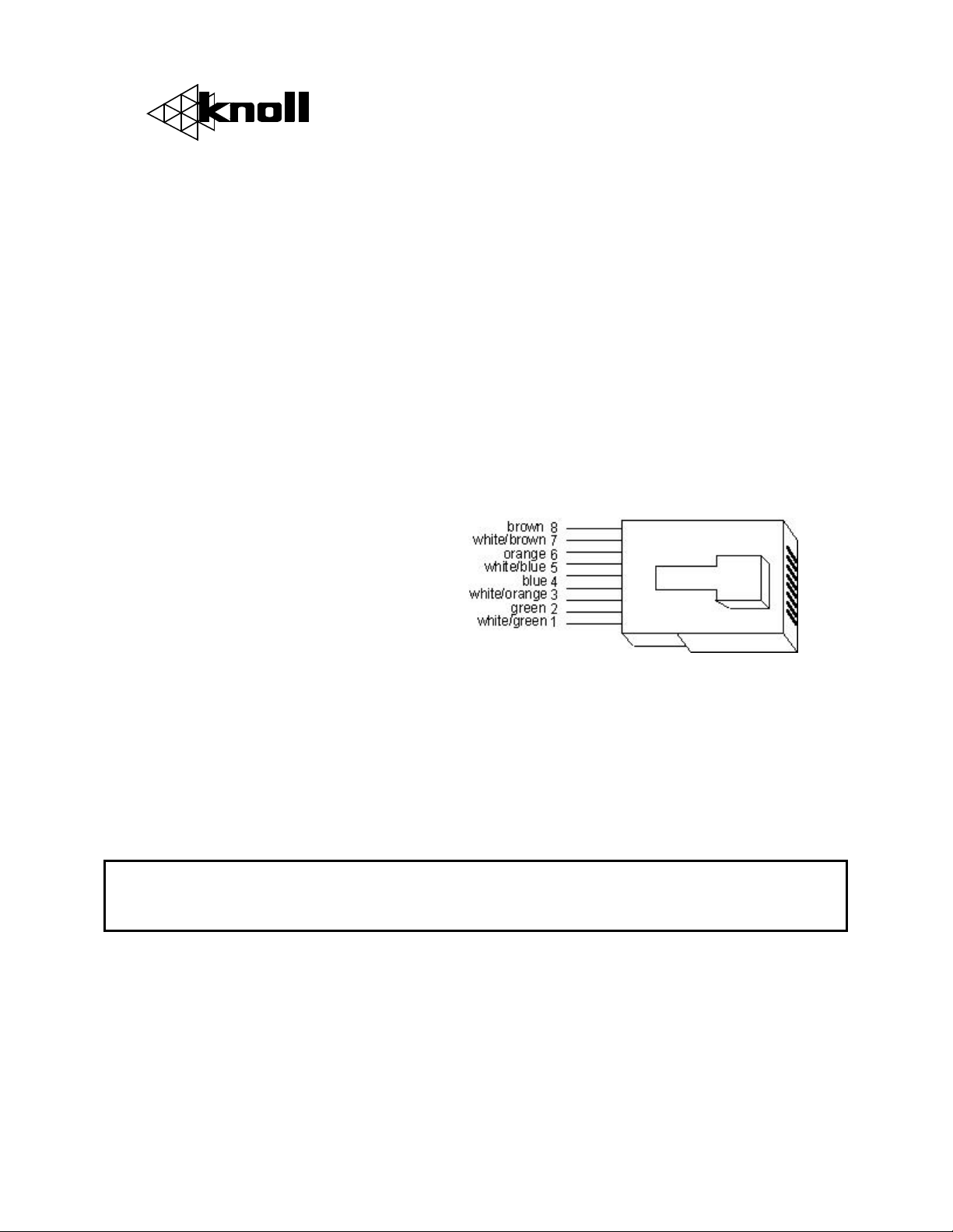
send and receive module are connected using a single cat 5 wire using 7 conductors.
Connection is made with the RJ45 connector (RJ45 plug not supplied). Always use
standard cat 5 wiring practices. Using the correct wire pairs and polarity is VERY
important.
Connection to video source equipment: Connect the UDS-SVID in-wall model or
US-SVID enclosure module to the source component (DVD, dish receiver, D-VHS, VCR,
stereo or other equipment) using a good quality, short as possible, s-video cable. If there
is a switched outlet on your output equipment, you may want to plug the PS1202 power
supply to the switched outlet.
Make sure a good quality RJ45 8-8 crimper is used to connect the RJ45 connector
to the cat 5 wire. Poor crimping and mismatched wires are the biggest cause of
installation problems.
Power requirements: The Knoll UTP send receive system requires a single PS1202
power supply connected to the send unit only. In certain cases with very long leads a
higher voltage PS1506 15 VDC power supply may be required if wavy or image video
lines are evident.
The Knoll UTP send receive system uses very little power and is normally left on or it can
be switched on and off with a switched outlet. A led lamp shows if power is connected
properly on both the send and receive unit.
Page 2
Connection to the Projector, TV or other components: Connect the UDR-SVID
inwall model or UR-SVID enclosure module to the input s-video jack using a good quality,
short as possible, s-video cable to the projector, plasma, TV or other component. Make
sure the correct projector, plasma, TV or other s-video input is selected.
Multiple Connection(s): If the component signal needs to be sent to more than one
receiver, this can easily be accomplished by daisy chaining the Knoll s-video senders. The
US-SVID and/or UDS-SVID sender needs to have their s-video inputs Y-corded together.
Each sender is connected via one cat 5 wire to one UR-SVID or UDR-SVID receiver (as
above). Two 75 ohm through hole resistors in all but one of the senders need to be
snipped. For example, if four senders are being Y-corded together, three (not all four) of
the US-SVID and/or UDS-SVID senders need to be opened up and have the three 75
ohm through hole resistors beside the s-video jack snipped off. Receive units do not have
any alterations. Each send unit requires a PS1202 power supply.
To loop from a local source going to a local component (such as a TV) using Y-cords, the
two 75 ohm resistors in the send unit MAY need to be snipped.
Infrared: The Knoll stereo balun system can carry infrared signals from the receive unit
to the send unit. To do this a three wire infrared receiver (not supplied) is connected to
the triple connection 3.5mm stereo jack on the receive unit. The receive unit supplies 12
VDC power for the receiver, so a separate infrared power supply is not required.
An IR54 or IR55 connection module is connected using the ground and IR output
terminals on the IR54 or IR55 and a mono 3.5mm jack connected to the send module.
The tip is the IR output. Infrared emitters are then connected to the IR54 or IR55. If an
emitter is directly connected to the send unit without a connection block, a 470
ohm dropping resistor needs to be inserted in series in the emitter wire or the emitter
will fail after a short period of time. Any infrared commands sent from the receiver on
the Knoll stereo receive balun end is sent to the infrared emitter on the Knoll stereo
balun send side and rebroadcast there.
If need be, please call our tech line for details at 1 800 566 5579.
* This product may contain lead that some states have determined are harmful. Wash
you hands after touching this product.
Warranty
Knoll Systems warrants its products sold in the USA and Canada by authorized Knoll dealers to be free of
defects in materials and workmanship. This warranty extends for three full years from the date of purchase by
the original consumer except for video projectors and video lamps. Any products returned to Knoll Systems and
found to be defective by Knoll Systems within the warranty period will be repaired or replaced at Knoll Systems
option, at no charge. Knoll Systems will not be responsible for the actual cost of installation or removal of the
product, nor for any incidental or consequential damages. Some states do not allow the exclusion or limitation
of incidental or consequential damages, so the above limitation may not apply to you. This warranty gives you
specific legal rights. You may have additional legal rights that vary from state-to-state.
Knoll Systems www.knollsystems.com
145 Tyee Drive Point Roberts, WA 98281
12140 Horseshoe Way Richmond, BC V7A 4V4
tel (604) 272 4555, fax (604) 272 5595
Made in Canada
US-UR SVID manual.doc
 Loading...