

Page 1
PIXEL™ Installation Instructions
Y-Leg Fixed-top Tables
Glides or casters
Related tables:
KYXW7236
KYXW8436
KYXW9648
* Casters shown
Unboxing
You should have received your top plus two boxes per table.
Box 1 includes:
Leg assemblies, hardware in a red plastic bag, and installa-
tion instructions.
Box 2 includes:
Horizontal rails
Please pay close attention to torque requirements.
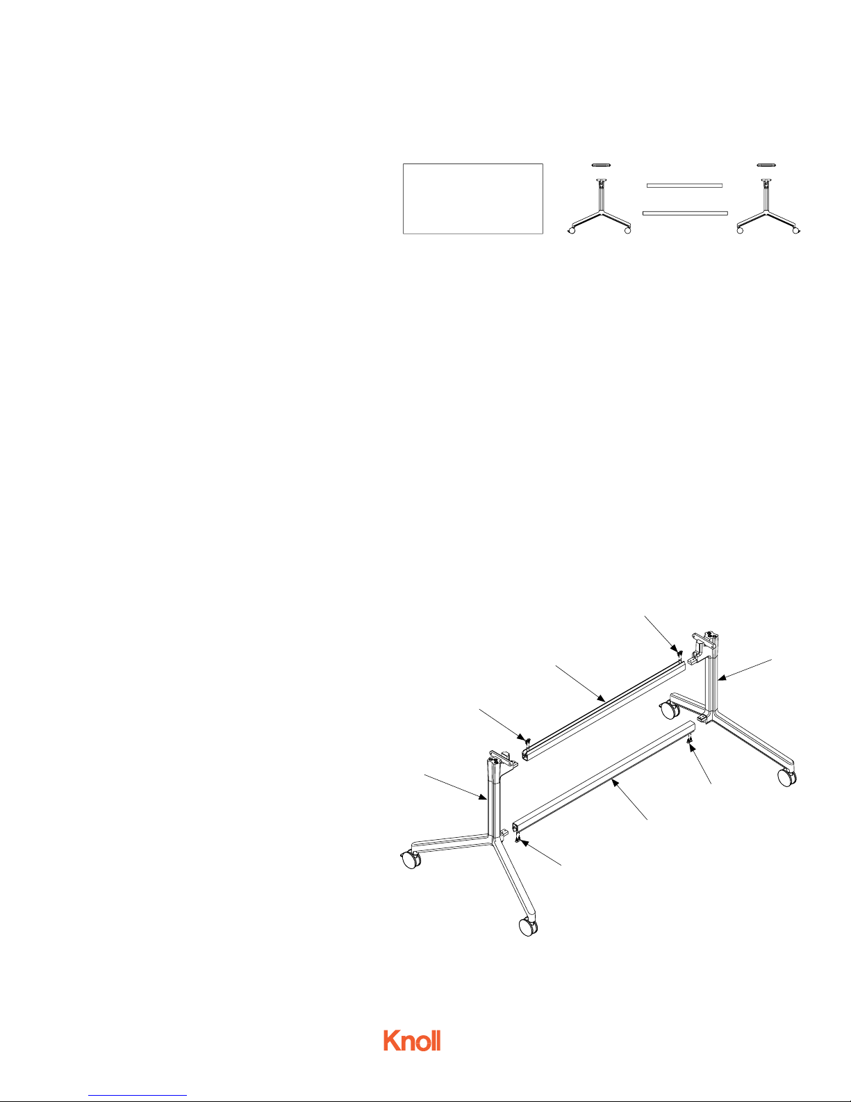
Step 1.
Attach the leg assemblies (A) on each end of the two
horizontal rails (B) with flat head 1/4 - 20 screws (C),
4 per rail. Use 5/32” allen wrench, torque: 50 in/lbs
Parts list
1 Table top
2 Leg assemblies
2 Horizontal rails
2 Top brackets
Tools needed
Allen wrenches
Phillips screwdriver
Torque wrench
C
Hardware
8 Flat head 1/4 - 20 screws
8 Socket cap 1/4 - 20 screws
4 5/16” Shoulder screws
2 Vertical wire management clips
(clear plastic)
4 Horizontal wire management clips
with wood screws
C
B
A
4AU6008 - Oct 2015
Page 1 of 2
A
C
B
Fig. 1
C
Page 2
PIXEL™ Installation Instructions
Y-Leg Fixed-top Tables
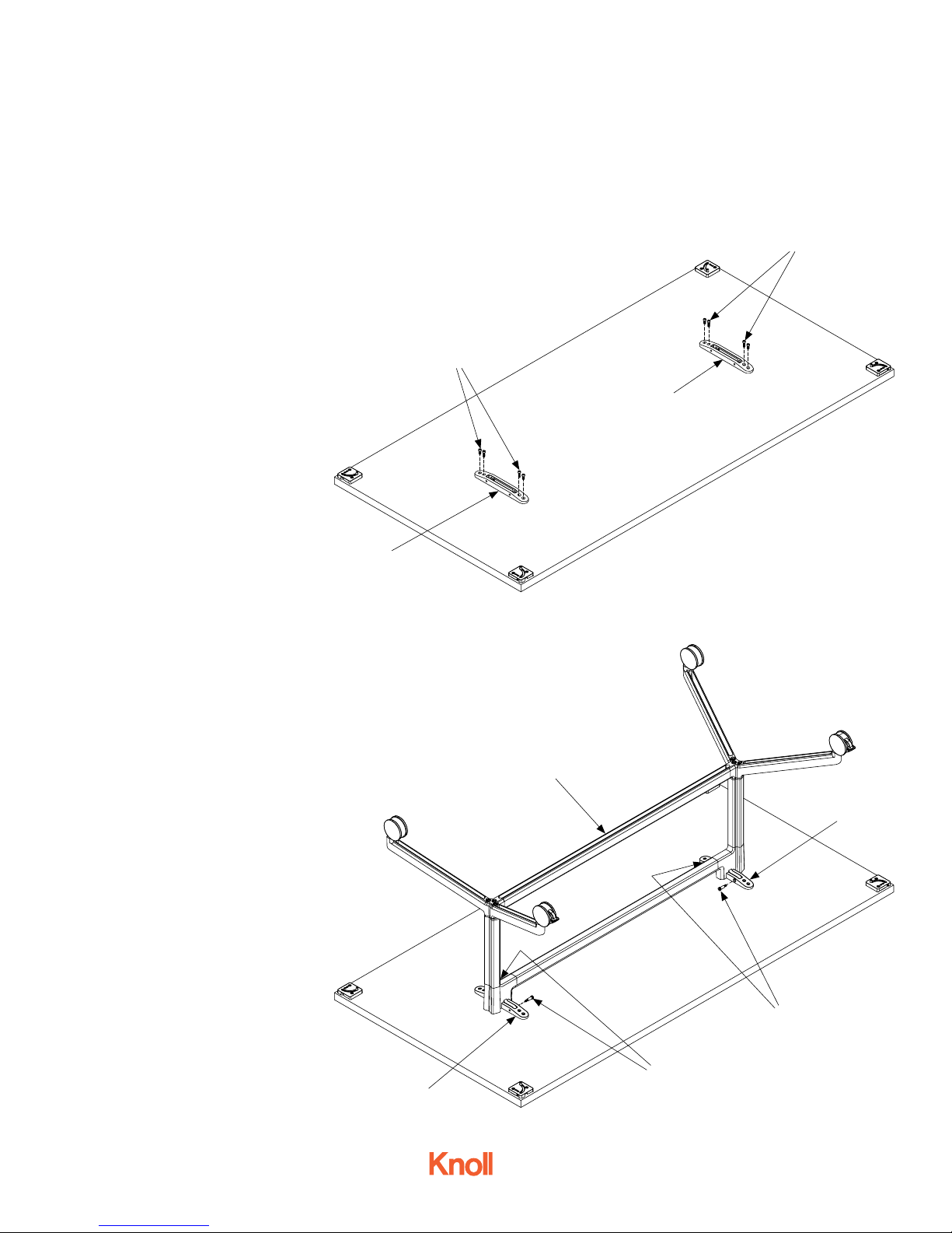
Step 2.
Lay the inverted table top on the floor.
E
Attach table top brackets (D) to table
top with socket cap head 1/4 - 20
screws (E) 4 per bracket. Use 3/16”
allen wrench, torque: 130 in/lbs
Step 3.
Position the leg and horizontal rail
subassembly (F) on the underside of the
top. Align and attach the leg and horizontal rail subassembly with the table top
brackets (G), using 5/16” shoulder screws
(H), 2 per casting. Use 5/32” allen wrench,
torque: 50 in/lbs.
Step 4.
Turn the table top assembly over into the
upright position.
E
D
Fig. 2
D
F
All tables come with 2 vertical wire
management clips, 4 horizontal wire
management clips and wood screws
for use with optional electronic modules. See separate electrical installation instructions for details.
If the table is being used as a
stand-alone piece and the ganging
mechanism will not be used, you can
remove the mechanisms by
unscrewing them.
4AU6008 - Oct 2015
Page 2 of 2
G
Fig. 3
H
H
G
 Loading...