

Knoll Pixel KBXL36DG, Pixel KBXC36DG, Pixel KBXW36DG, Pixel KBXB36DG, Pixel KBXL3030G Installation Instructions Manual
...Page 1
PIXEL™ Installation Instructions
Column Leg Tables
Glides only
Round tables:
KBXL36DG
KBXW36DG
KBXC36DG
KBXB36DG
Square tables:
KBXL3030G
KBXW3030G
KBXC3030G
KBXB3030G
Please pay close attention to torque requirements.
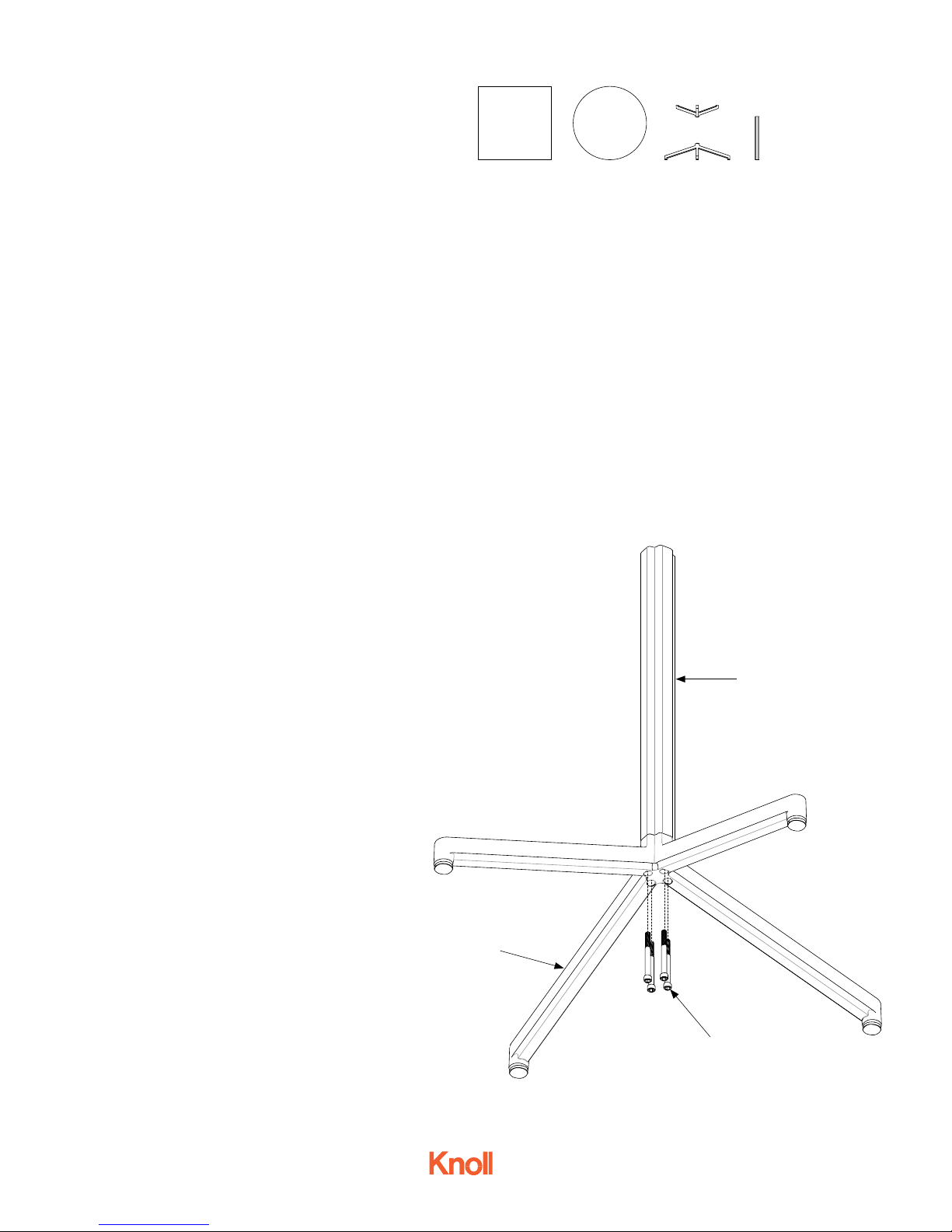
Step 1.
Attach the column extrusion (A) to the base (B)
using 4
socket cap head 5/16-18 x 3.00 screws
(C), torque: 200 in/lb.
Parts list:
1 Table top
1 Column extrusion
1 Top support
1 Base (with glides)
Tools needed:
Allen wrench
Torque wrench
Hardware:
8 Socket cap head 5/16-18 x 3.00 screws
(base/support to extrusion)
4 Socket cap head 5/16-18 x 2.00 screws
(base to top)
2 Vertical wire management clips
(clear plastic)
A
4AU6005 - Oct 2015
Page 1 of 3
B
C
Fig. 1
Page 2
PIXEL™ Installation Instructions
Column Leg Tables
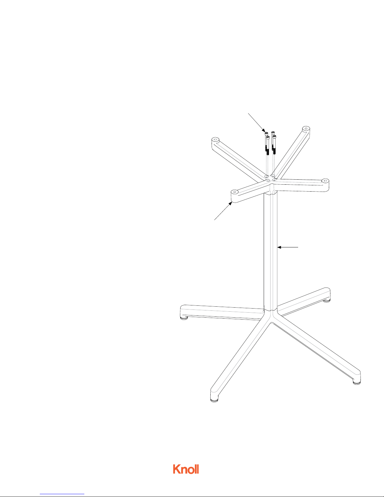
Step 2.
Attach the column extrusion and base (D) to the top
support (E) using 4 socket cap head 5/16-18 x 3.00
screws (F), torque: 200 in/lb.
F
E
D
4AU6005 - Oct 2015
Page 2 of 3
Fig. 2
Page 3

PIXEL™ Installation Instructions
Column Leg Tables
Step 3.
Lay the inverted table top on the floor.
Step 4.
Attach the base assembly (D) to the top using
4 socket cap head 5/16-18 x 2.00 screws (E),
torque: 130 in/lb.
D
Step 5.
Turn the assembled table into the upright
position.
All tables come with 2 vertical wire management clips for use with optional electrical
modules. See separate electrical installation
instructions for details.
E
4AU6005 - Oct 2015
Page 3 of 3
Fig. 3
 Loading...