

Knoll KCXA4818, KCXA4824, KCXA6018, KCXA7218, KCXA6024 Installation Instructions Manual
...Page 1
PIXEL™ Installation Instructions
C-Leg Height Adjustable Fixed-top Tables
Glides or casters
Related tables:
KCXA4818
KCXA6018
KCXA7218
KCXA4824
KCXA6024
KCXA7224
KCXA4830
KCXA6030
KCXA7230
* Glides shown
Unboxing
You should have received your top plus two boxes per table.
Box 1 includes:
Leg assemblies, table top support castings, hardware in a
red plastic bag, and installation instructions.
Box 2 includes:
Wire management trough and flip door.
Please pay close attention to torque requirements.
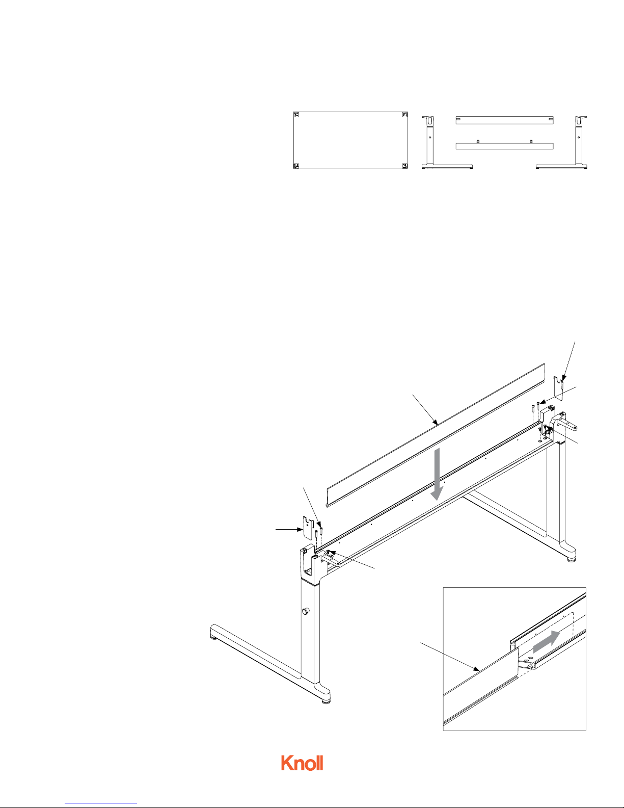
Step 1.
Slide the flip door (A) in from the end of the
wire management trough groove.
Parts list
1 Table top
1 Left C-leg assembly
1 Right C-leg assembly
2 Table top support castings
1 Wire management trough
1 Flip door
Tools needed
Allen wrenches
Torque wrench
Phillips screwdriver
B
Hardware
4 Socket cap head 1/4”-20 x 1” screws
4 Socket cap head 1/4”-20 x 2” screws
4 Flat head 1/4”-20 x 1/2” screws
10 Socket cap head 5/16”-18 x 1” screws
2 Vertical wire management clips
(clear plastic)
4 Horizontal wire management clips
with wood screws
A
D
B
C
Step 2.
Attach the wire management trough to the
C-legs. Use socket cap head 1/4”-20 x 1”
screws (B), 2 per leg, use 5/32” allen wrench,
torque: 50 in/lb. Use flat head 1/4”-20 x 1/2”
screws (C), 2 per leg, use 3/16” allen wrench,
torque: 50 in/lb.
Step 3.
Drop the trough end covers (D)
into the slots on each leg upper
casting.
Fig. 1
4AU6011 - Oct 2015
Page 1 of 4
D
C
A
Fig. 2
Page 2
PIXEL™ Installation Instructions
C-Leg Height Adjustable Fixed-top Tables
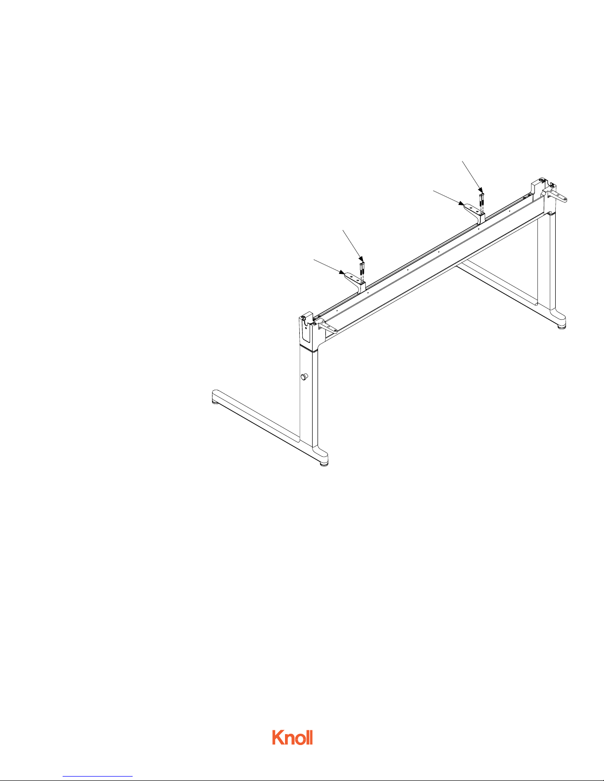
F
Step 4.
Attach the two table top supports (E) to the trough with
socket cap head 1/4”-20 x 2” screws (F), 2 per support,
torque: 50 in/lb.
E
F
E
Fig. 3
4AU6011 - Oct 2015
Page 2 of 4
Page 3

PIXEL™ Installation Instructions
C-Leg Height Adjustable Fixed-top Tables
Step 5.
Lay the inverted table top on the floor. Position the
leg-trough assembly on the underside of the top.
Step 6.
Align and attach the brackets with the threaded
inserts in the top using 10 socket cap head
5/16”-18 x 1” screws (G), torque: 130 in/lb.
G
Step 7.
Turn the table top assembly over into the upright
position.
All tables come with 2 vertical wire
management clips, 4 horizontal
wire management clips and wood
screws for use with optional electrical modules. See separate electrical
G
installation instructions for details.
If the table is being used as a
stand-alone piece and the ganging
mechanism will not be used, you
can remove the mechanisms by
unscrewing them.
G
G
Fig. 4
4AU6011 - Oct 2015
Page 3 of 4
Page 4

PIXEL™ Installation Instructions
C-Leg Height Adjustable Fixed-top Tables - Operating Instructions
To adjust the table height:
Step 8.
Begin on one side of the table. Rest your foot on the lower
casting (H).
Step 9.
Pull the spring pin knob (I) and lift table top to the desired
height
Step 10.
At the approximate desired height, let the top slide downwards until the spring pin re-engages in the lock position.
I
Fig. 5
H
Step 11.
Go to second side. Pull pin (J) and lift to height desired.
Let pin re-engage.
The maximum height is 34 inches measured from the top
of the table to the floor.
All tables come with 2 vertical wire management clips, 4
horizontal wire management clips and wood screws for
use with optional electrical modules. See separate electrical installation instructions for details.
J
Fig. 6
4AU6011 - Oct 2015
Page 4 of 4
Fig. 7
 Loading...