

Page 1
IR155 Infrared Connection Module
Specifications:
Specifications
Infrared carrier frequency: 1-1,000,000 Hz
Maximum wire length: 1000’ (300m) or even more with
larger gauge wire
Wire requirements: 3 conductors, minimum 24-gauge
to 200’; 22-gauge up to 500’;
20-gauge to 1000’
Power requirements: 12VDC, 200mA+
Dimensions: 2.5” x 1” x 2-5/8"
(63mm x 26mm x 67mm)
Requires 12VDC power supply, emitter(s) and a Knoll
infrared receiver.
Warranty
Knoll Systems warrants its products sold in the USA and Canada by authorized
Knoll dealers to be free of defects in materials and workmanship. This warranty
extends for three full years from the date of purchase by the original consumer.
Any products returned to Knoll Systems and found to be defective by Knoll
Systems within the warranty period will be repaired or replaced at Knoll Systems
option, at no charge. Knoll Systems will not be responsible for the actual cost of
installation or removal of the product, nor for any incidental or consequential
damages. Some states do not allow the exclusion or limitation of incidental or
consequential damages, so the above limitation may not apply to you. This
warranty gives you specific legal rights. You may have additional legal rights
that vary from state-to-state.
Knoll Systems www.knollsystems.com
145 Tyee Drive Point Roberts, WA 98281
14-7163 Vantage Way, Delta BC V4G 1N1
Telephone: (604) 940-1689, Fax (855) 734-3363
www.knollsystems.com
Made in Canada Knoll Systems All Rights Reserved
IR155
Infrared Connection Module
Installation Instructions v2.0
Warning: To be installed and/or used in accordance with
appropriate electrical codes and regulations.
Introduction: Thank you for your purchase of a Knoll IR155
infrared connection module. This module is the heart of a
scalable infrared repeater system. The IR repeater system can
pick up a remote control signal and relay it on wires to the
inside of a cupboard or another location up to 1000’ (or more).
Features:
Easy to install and easy to
use
No maintenance
Connect up to twelve infrared
receivers
Connect up to eight emitters
to four emitter ports
One emitter port is dimmable
for use with oversensitive components.
Industry standard color coded jacks.
Knoll PS1205 power supply recommended
Installation Tips
1. Follow all local electrical & building code requirements.
2. The IR155 is usually mounted with the stereo and/or video
equipment it is helping to control.
3. Wires to the infrared receivers can be solid or stranded,
shielded or unshielded with a minimum of 28-gauge for runs
under 200’, 22-gauge for runs under 500’ and 20-gauge for
runs up to 1000’. Wires can be looped from infrared receiver to
receiver or home run. Home runs normally offer more reliability
and future flexibility.
Page 2
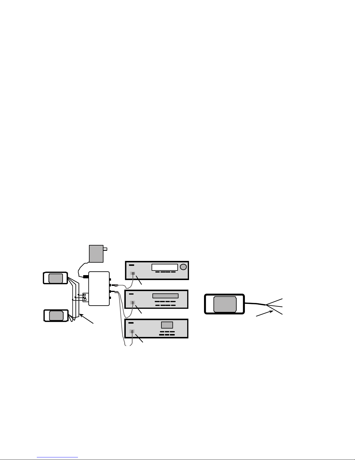
Receiver
CD
IR31A
IR34A
IR155
PS1205
12 V DC Power Supply
Dish
IR34A
171
Connection
Block
Note: IR220’s are
wired in parallel
12V
GND
SIG
Wire with
printing
Wire w ith
printing
IR OUT Signal
GROUND
+12 VDC
IR220
4. Knoll infrared receivers can be mixed and matched in larger
systems with up to 12 Knoll infrared receivers per system.
5. When connecting Knoll infrared receivers to the IR155
detachable connector, make sure the infrared receivers are
wired in parallel only. Some Knoll infrared receivers have a red
plug connected. It can be connected to the IR155 red jack. If
the wire length is longer or the receiver does not have a red
plug use the following procedure:
Connect the infrared receiver(s) 12V, GND and SIG terminals
to the corresponding IR155 screw terminals. Prepare the wire
leads to and from the IR receivers by stripping about ¼” of the
insulation from each of the three leads. Twist the strands tightly
together so that they do not stick out of the connector and
cause a short circuit. Strictly observe polarity. See the Knoll
infrared receiver manual for wire identification.
6. Next, plug the single or dual emitters into the IR155
connection block and position the emitters over the component
to be controlled infrared receiver window (and glue it down).
Clear acrylic glue works well if the included double sided sticky
tape doesn’t work as needed.
Emitter port 1 is dimmable. In most cases the pot should be
turned fully on (fully clockwise). In certain cases when emitters
are attached to overly
sensitive components
(that IR signals don’t reliably work) emitter port 1 can be
helpful. If this is the case attach the emitter and start by dialing
back the emitter pot ½ way and experiment to see if the
infrared signal is more reliable. Adjust the pot further as
needed.
7. Plug in the PS1205 power supply.
8. The infrared system is usually left plugged in all the time (to
an unswitched outlet) as it uses very little standby power.
9. Test the infrared system to see if it is working properly.
Bright sunlight and passive infrared security systems can lower
the distance that remote controls can work with the Knoll
infrared receiver(s).
Note: When using more than 150 foot (50m) lengths of shielded
wire it may be necessary to add a 470 ohm 1/4w resistor
between the IR155 “GND” and “IR OUT” to discharge cable
capacitance.
If you have any questions or concerns, please call and ask for
infrared technical support at 1 800 566 5579. The help line is
open from 7:30 a.m. to 4:00 p.m., Monday to Friday, Pacific
time.
Fig. 1 Connection Diagram with IR220’s shown
 Loading...