

Page 1
DIR21P Digital Infrared Receiver Specifications:
Specifications
Infrared carrier frequency: 30-60kHz
Indoor reception range: 150 feet + (45 meters +)
Outdoor reception range: 35-50 feet (10-15 meters)
Nominal reception angle: 50 degrees off axis
Wire requirements: three conductor, minimum 24
Gauge to 200’, 22 gauge up to 500’
20 gauge to 1000’
Power requirements: Unregulated 12VDC, 40mA
Dimensions:
1-3/4" x 4" x 1"
(45mm x 102mm x 26mm)
Requires 12VDC power supply and emitter.
Warranty
Knoll Systems warrants its products sold in the USA and Canada by authorized
Knoll dealers to be free of defects in materials and workmanship. This warranty
extends for three full years from the date of purchase by the original consumer.
Any products returned to Knoll Systems and found to be defective by Knoll
Systems within the warranty period will be repaired or replaced at Knoll Systems
option, at no charge. Knoll Systems will not be responsible for the actual cost of
installation or removal of the product, nor for any incidental or consequential
damages. Some states do not allow the exclusion or limitation of incidental or
consequential damages, so the above limitation may not apply to you. This
warranty gives you specific legal rights. You may have additional legal rights
that vary from state to state.
Knoll Systems www.knollsystems.com
145 Tyee Drive Point Roberts, WA 98281
12140 Horseshoe Way Richmond BC V7A 4V4
tel (604) 272 4555, fax (604) 272 5595
Made in Canada Knoll Systems All Rights Reserved
DIR21P
Digital Infrared Receiver
Installation Instructions v1.1
Warning: To be installed and/or used in accordance with
appropriate electrical codes and regulations.
Introduction: Thank you for your purchase of a Knoll
DIR21P digital infrared receiver. This receiver features a long
indoor usable range and it can be used in direct sunlight and
near plasma and other TV’s. It is designed to act as a remote
receiver of remote control signals that when passed through a
connection module and emitters, relays remote infrared
commands to equipment in a distant room. It is very similar to
the DIR21 with an added internal processor, so a connection
block is not needed. A single or dual emitter can be connected
to the DIR21P
Features:
• Inwall junction box design,
available in white, ivory, almond
and black colors.
• Digital processor included for
direct hook up to emitters
without a connection block.
• Will relay almost all remote
control types (except some
•
Wire run can be 1000’ (300m)
or more
ery little power.
Requires v
•
Suggest using Knoll PS1202 12 vdc.
modB & O and Pioneer Elite
els).
System
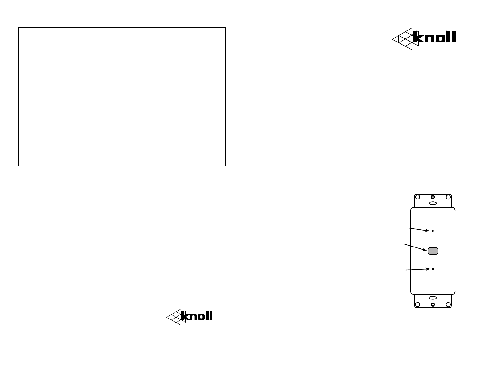
power
on LED
IR
Receiver
Blue
talkback
LED
Page 2
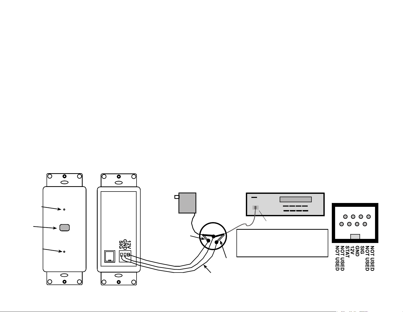
Installation Tips
. Follow all local elect1
. The DIR21 is usually wall mounted at light switch heigh2
does not normally require a junction box. In order to work it
requires a PS1202 (200 mA) or PS1205 (500 mA) 12 VDC
unregulated power supply, IR31 (single) or IR34 (dual) emitt
A connection block is not needed.
. The three conductor in wall wi3
1000’. Wires can be solid or stranded, shielded or unshield
with a minimum of 28 gauge for runs under 200’, 22 gauge fo
runs under 500’ and 20 gauge for runs up to 1000’.
. Cut off the plugs of both the PS1202 power suppl4
emitter to be used. Strip back and connect the two – or groun
wires of the power supply and emitters (non white stripe on
wire) together with the wire conductor going to the “GND”
terminal of the DIR21P. Next connect the emitter + wire (the
one with the white stripe) to the wire going to the DIR21P “SI
terminal. Then connect the PS1202 power supply + wire (the
one with the white stripe) to the wire going to the “12V”
terminal on the DIR21P. Polarity must be strictly observed.
rical & building code requirements.
t. It
re can be extended up to
ed
y and the
er.
r
d
G”
5. Position the emitters over the IR receivers on the
component(s) to be controlled, plug in the PS1202 power supply
and the system should be ready to go.
6. The infrared system is usually left plugged in all the time (to
an unswitched outlet) as it uses very little power.
7. Test the digital infrared system to see if it is working
properly. If it works only from a very close range or it does not
work at all, first mark where the pot adjustment is on the
DIR21P blue color pot on the rear of the DIR21P. This is so you
can reset it to that starting point again. Try adjusting the pot on
the connection block very slightly left and right as you are
testing the receiver with the remote control. This may require
two people. This should correct for the problem. If it still does
not work properly, please call Knoll Systems and ask for infrared
technical support at 1-800-566-5579. The help line is open from
7:30 a.m. to 5:00 p.m. Monday to Friday Pacific time.
Blue
talkback
LED
IR
Receiver
Blue
talkback
LED
DIR21P
Digital
Infrared
Receiver
RJ45
PS1202 +12VDC
wire has white
stripe. If in doubt
test with a voltmeter.
PS1202
12 V DC
Power Supply
Cut off power supply and emitter
plugs, strip back insulation and
join with inwall wires as shown.
Grounds or - are common.
Emitter white
stripe wire is SIG
Three conductors from power
supply and emitter to DIR21P
CD
IR31A
RJ45
 Loading...