

Page 1
Installation and
Operating
Instructions DC100 Door Chime
Module
Congratulations and thank you for choosing this
Knöll product. The DC100 door chime module is
specifically designed for use with the MVP64 and
Grande controller-amps as well as the Ultimo and
MR640 controllers. It features connections for up
to three lighted or non-lighted push button door
buttons (front, side and rear door) with has two
sound bank selections (6 chime sounds in all).
When activated by pressing any of the three door
buttons, the DC100 sends a digital signal to the amp
or controller to turn on or “override” all zones to a
preset volume then runs the chime sound at a gain
set by the installer. After the door chime sound
ends, all zones revert to their previous volume and
input states.
Installation
The DC100 requires that door buttons are normally
open, momentary style. Lighted buttons should be
12-24 volts that short out while the button is
pushed. The system should only be installed with
the amp-controller powered off and the mains
power is unplugged.
Power for the DC100 is from the PS1202 power
supply (included) and is usually left on.
Running wire
Any conventional two-conductor wire is adequate
for most installations. Runs longer than 100 feet
(33 meters) should use minimum 18-gauge wire, as
the power to the lighted door buttons will be
limited. Run a home run from each of the up to
three door button locations to the DC100.
Connect the wires and install the door button as
the manufacturers instructions advise.
Caution: In retrofit applications make sure the
“old” power supply is disconnected from the door
button wires or major system damage could occur.
Connecting door buttons to the
DC100
The detachable four-position connector on the
DC100 is connected to the up to three door chime
buttons. Each of the three positions run two
different chime sounds depending on the bank
position switch.
Chime Sounds
Bank
Switch
Switch
In
Switch
Out
Some chime sound experimentation may be
required. Smaller speakers generally do better with
low tones and larger speakers do better with high
tones. All three chime sounds have to come from
the same bank (in or out).
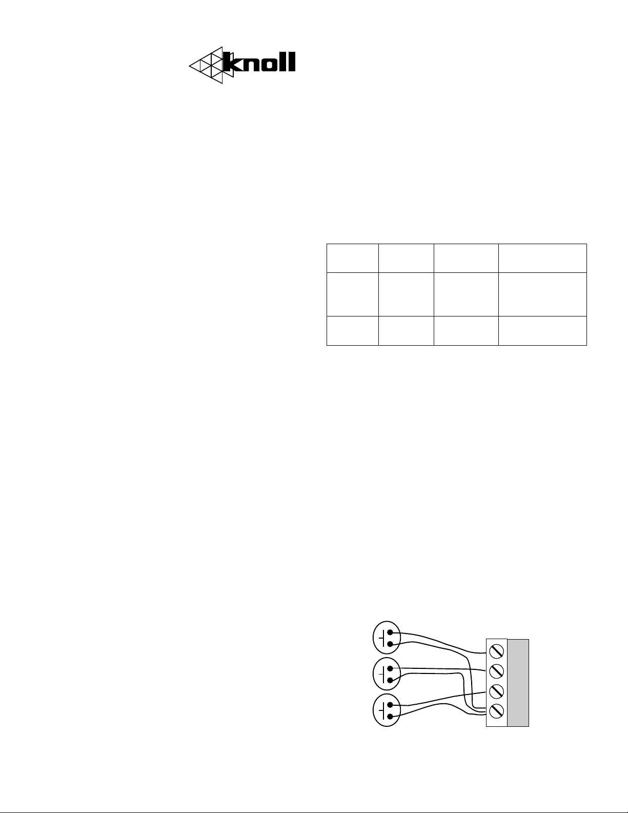
Connect one of each of the up to three wires from
each of the door buttons to the detachable
connector labeled “G”. Most lighted door buttons do
not have polarity.
Connect the conductor of one of the door buttons
to front, rear or side position of the detachable
DC100 connector.
Connect the conductor of the next button to one of
the two open positions on the detachable connector.
Connect the last conductor to the last open
terminal on the detachable connector.
Front
button
Rear
button
Side
button
Front Rear Side
Ding
(high
tone)
Big Ben
(8 tones)
Ding Dong
(high tone)
Ding Dong
(low tone)
Ding Dong Ding
(high Tone)
Ding Dong Ding
(low Tone)
DC100 Connector
Front
Rear
Side
Common
Page 2

If two buttons are connected to the same
detachable terminals, the DC100 will chime the
same for the two buttons. It also may not provide
enough power for lighted buttons.
Do not terminate or connect unused detachable
terminal connections.
Connecting the DC100 to the amp or
controller
If the Source 4 input on the controller or
controller amp is not being used skip the rest of
this paragraph. If you are still reading this, then
connect the stereo source input planned for Source
4 to the “In” RCA jacks on the DC100 chime module.
Next connect the DC100 “Out” RCA jacks to the
controller or controller-amp Source 4 inputs using a
gold stereo RCA wire.
If this installation has more than one controller
and/or controller-amp use good quality Y cords to
connect each of the controller Source 4 jacks (in
parallel) to the DC100 stereo jacks labeled out.
Next connect the DC100 data port to the
controller or controller-amp data port using the
supplied 3.5mm stereo jack/cable.
DC100 Power
Using the provided PS1202 power supply connect
the power supply to the DC100 and plug the power
supply into full time unswitched power. If the
power is switched off then the door chimes will not
work!
Setting the gain.
The controller or amp-controller should be fully
installed with speakers to test it and set the gain.
We suggest that the DC100 gain be turned down
before testing the door chimes.
Turn the controller or controller amp on to standby
and any extra amps connected into the system.
Have someone push the door button and listen to
the level. Adjust it as desired. Some
experimentation with the chime sounds may be in
order. Most of our dealers feel the ding dong (low
tone) chime sound is the best to start with. After
adjusting the level it is important to check all of
the other zones to hear if they are being
overloaded by the chime sound. If they are, then
the DC100 gain (of the whole system) has to be
lowered.
Operation
The system operation should be quite
straightforward.
Press the door chime button and the chime is
sounded throughout the system.
When activated by pressing any of the three door
buttons, the DC100 sends a digital signal to the amp
or controller to turn on or “override” all zones to a
preset volume then runs the chime sound at a gain
set by the installer.
After the door chime sound ends, all zones revert
to their previous volume and input states.
Occasionally the system may become confused if a
door chime was pressed while something else was
going on in the command system of the controller or
amplifier controller. In this case just change the
input or shut the system down as desired from any
keypad. If this does not work turn the power off
then on to the controller or controller amp and the
system will reset.
DC100 size is 143x83x45mm (5.6"x3.25"x1.75").
Knoll Systems Point Roberts, WA USA and
Richmond BC Canada tel: 604 272 4555
2002 Knöll Systems. All rights reserved v1.1
 Loading...