

Page 1
CUT-IR Infrared Receiver Specifications:
Specifications
Infrared carrier frequency: 20-100kHz
Maximum wire length: 1000’ (300m) or more with larger
gauge wire
Wire requirements: 2 conductors, minimum 24-gauge
to 200’; 22-gauge up to 500’;
20-gauge to 1000’
Dimensions: 1” x 1.5” (25mm x 38mm)
Cord length 75” (2 meters)
Requires 12VDC power supply, infrared receivers(s) and
connection block.
Warranty
Knoll Systems warrants its products sold in the USA and Canada by authorized
Knoll dealers to be free of defects in materials and workmanship. This warranty
extends for three full years from the date of purchase by the original consumer.
Any products returned to Knoll Systems and found to be defective by Knoll
Systems within the warranty period will be repaired or replaced at Knoll Systems
option, at no charge. Knoll Systems will not be responsible for the actual cost of
installation or removal of the product, nor for any incidental or consequential
damages. Some states do not allow the exclusion or limitation of incidental or
consequential damages, so the above limitation may not apply to you. This
warranty gives you specific legal rights. You may have additional legal rights
that vary from state-to-state.
Knoll Systems www.knollsystems.com
145 Tyee Drive Point Roberts, WA 98281
14-7163 Vantage Way, Delta, BC V4G 1N1
Telephone: (604) 940-1689, Fax: (855) 734-3363
Made in Canada Knoll Systems All Rights Reserved
CUT-IR
Cutable, Bendable, Blocking,
Blue Blinking Infrared Emitter
v1.0
Warning: To be installed and/or used in accordance with
appropriate electrical codes and regulations.
Introduction: Thank you for your purchase of a Knoll CUT-
IR infrared emitter. This unique emitter is a blocking style (does
not permit other infrared signals to be read by the component
receiver) that can be cut (with scissors) to almost any size and
shape to become a non blocking emitter. The CUT-IR is
designed to be installed directly over the IR sensor window of
the controlled device. It is the only emitter on the market that
can be installed on non-flat surfaces, as it can bend around
uneven component surfaces. It also features a blue color
blinking talkback led to give visual confirmation that the infrared
remote signal is being rebroadcast to the component.
Features:
Can be cut with scissors from an
infrared blocking emitter to non
blocking
Can be bent to attach to non-flat
IR sensor windows.
Blue color visable talkback led can
be covered with black tape to remove talkback
indication
Industry standard yellow color 3.5mm plug jacket.
Page 2
Attaching the emitter to the IR sensor window
First decide if the CUT-IR will be blocking (does not permit other
infrared signals to be read by the component receiver) or nonblocking to other infrared signals on the controlled device.
The bendable CUT-IR shell does not allow other infrared signals
to pass through it.
If it is to be non-blocking; use a pair of scissors to cut down the
size of the emitter as desired. Thin guide lines are etched into
the CUT-IR surface so that the emitter can be cut square. Be
careful not to cut the wires or components on the emitter.
Locate the IR sensor window on the component and test that
the emitter is in the correct position before removing the
emitters adhesive layer protector. In some cases it may be
difficult to find the location of the component IR sensor. Consult
the owners manual or manufacturer if this location is not readily
apparent.
Once the IR sensor window is located and emitter has been
tested, remove the emitters adhesive cover and affix the CUT-IR
with its underside emitter leds positioned to the center of the
component to be controlled IR sensor window. The CUT-IR can
be bent around uneven surfaces and will continue to stick
perfectly.
Connecting the CUT-IR
Simply insert the mono 3.5mm mini plug of the CUT-IR into any
of the “EMITTERS” jacks on a Knoll Systems connecting block
such as the IR55.
CAUTION: Never connect the CUT-IR directly to a power supply
as it will instantly destroy the emitter and there is no visual
indication that it has been destroyed. If it still works it can be
tested with a common diode checker.
If you are more technically advanced and need to do so, the
yellow plug can be snipped off and the wires directly connected
without a connection block. The wire with the white stripe is
positive.
If you have any questions or concerns, please call the Knoll
Systems technical support at 1 800 566 5579. Technical support
is available from 6:30 a.m. to 4:30 p.m., Monday to Friday,
Pacific time.
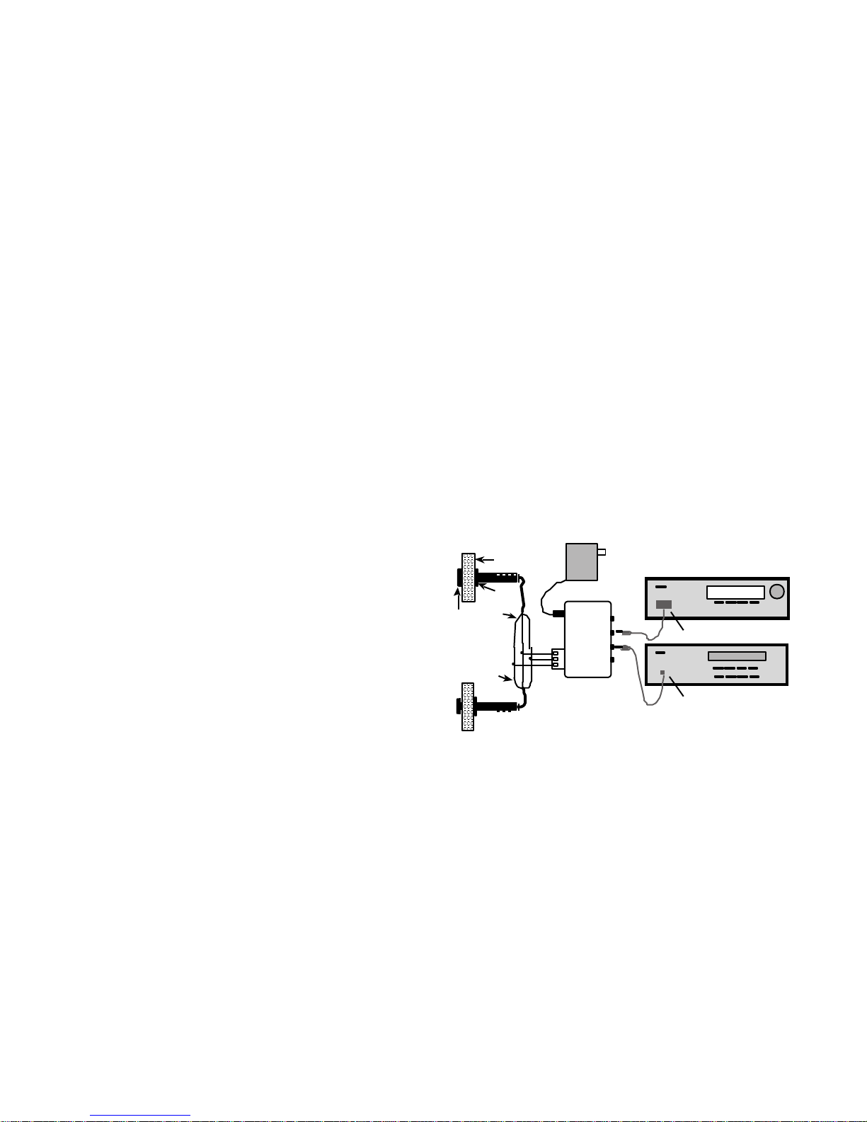
Receiver
CD
CUT-IR shown blocking
CUT-IR shown
non-blocking
IR55
PS1205
12 V DC Power Supply
Connection
Block
Note: IR230’s are
wired in parallel
12V
GND
SIG
Wh ite
Wire
Panel
nut
Bezel
IR230
White
W ire
IR230
TYPICAL INSTALLATION
 Loading...